$36
Gehl R190, R220 & R260 Manitou-Mustang 1900R, 2200R 2600R Skid-Steer Loaders Service Manual 50950134
Gehl R190, R220 & R260 Manitou-Mustang 1900R, 2200R, 2600R Skid-Steer Loaders Service Manual 50950134 – PDF DOWNLOAD
FILE DETAILS:
Gehl R190, R220 & R260 Manitou-Mustang 1900R, 2200R, 2600R Skid-Steer Loaders Service Manual 50950134 – PDF DOWNLOAD
Language : English
Pages : 328
Downloadable : Yes
File Type : PDF
Size: 155 MB
IMAGES PREVIEW OF THE MANUAL:
DESCRIPTION:
Gehl R190, R220 & R260 Manitou-Mustang 1900R, 2200R, 2600R Skid-Steer Loaders Service Manual 50950134 – PDF DOWNLOAD
INTRODUCTION:
- With correct maintenance and proper use, the Gehl R190, R220, R260 and Manitou/Mustang 1900R,
2200R and 2600R skid-steer loaders will give years of dependable service. This service manual is
intended to be a guide in the assembly and disassembly, installation and removal, adjustment and
testing, troubleshooting and replacement of components that together make up the Gehl and Manitou/
Mustang R-Series skid-steer loaders. - In many of the procedures found within, the installation steps are the exact opposite of the removal steps,
and therefore the opposite procedure is not written. Instead, a note to reverse the procedure is stated. This
reduces redundancy and excessive pages in the manual. In cases though, where the assembly and
disassembly or removal and installation procedures differ, and additional steps or safety concerns are
paramount, the entire reverse procedure is written to include the additional information. - The Table of Contents and the Index can be used to make finding a procedure easier. Many schematics,
photographs and line art drawings are used to help perform the necessary repairs, tests and adjustments
that the skid-steer loader needs to keep it in good running condition. - If you have any questions, please contact your authorized Gehl or Mustang dealer, or call the Gehl and
Mustang Service Department for assistance.
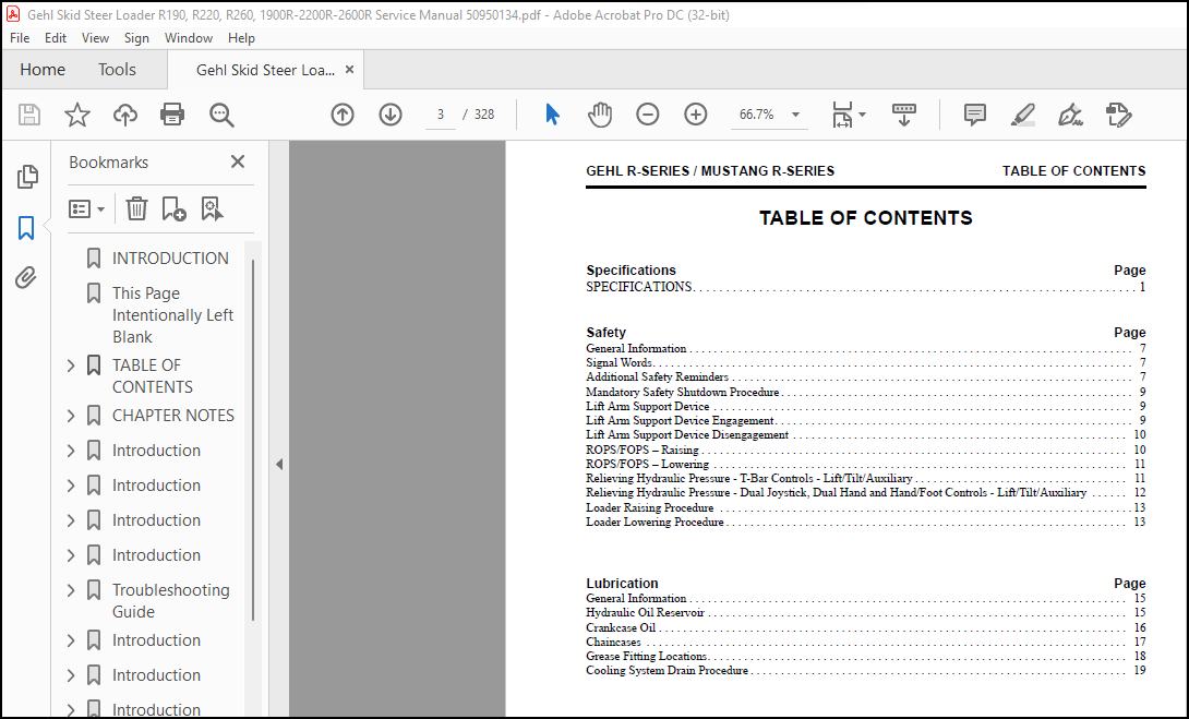
TABLE OF CONTENTS:
Gehl R190, R220 & R260 Manitou-Mustang 1900R, 2200R, 2600R Skid-Steer Loaders Service Manual 50950134 – PDF DOWNLOAD
INTRODUCTION 2
This Page Intentionally Left Blank 327
TABLE OF CONTENTS 3
SPECIFICATIONS 9
SPECIFICATIONS 11
SPECIFICATIONS 13
General Information 15
Signal Words 15
DANGER 15
WARNING 15
CAUTION 15
Additional Safety Reminders 15
Mandatory Safety Shutdown Procedure 17
Lift Arm Support Device 17
WARNING 17
Lift Arm Support Device Engagement 17
1 Remove attachment from lift arm 17
2 Raise the lift arm fully 17
3 Turn keyswitch to OFF position to stop engine 17
4 Have an assistant remove the lift arm support device from its storage location on the left side of the machine Remove the lynch pin holding the support device up against the lift arm Allow the support device to come down into contact with the li 17
5 Restart the engine 17
6 Use the lift control to raise the lift arm until the support device drops over the end of the lift cylinder and around the cylinder rod Slowly lower the lift arm until the free-end of the support device contacts the top end of the lift cylinder 17
7 Look to be sure the support device is secure against the cylinder end Then, stop the loader engine, remove the key and leave the operator’s compartment 17
8 Stop the engine, and exit the machine 17
Lift Arm Support Device Disengagement 18
WARNING 18
1 Raise the lift arm fully 18
2 Turn the keyswitch to the OFF position to stop the engine and remove the key 18
WARNING 18
3 To store the lift arm support device, have an assistant raise it up until it contacts the lift arm Reinstall the lynch pin through the welded steel post on the lift arm 18
ROPS/FOPS – Raising 18
1 The lift arm should be either fully lowered or locked in the raised position per the “Lift Arm Support Device Engagement” procedure in this chapter 18
2 Turn the keyswitch to the OFF position to stop the engine Remove the key and take it with you 18
3 Leave the operator’s compartment 18
WARNING 18
4 Remove one hex nut, washer and capscrew on each side of the ROPS/FOPS lower corners 18
5 Grip the front grab handles at the front of the ROPS/FOPS and push up and back until the self- actuating lock mechanism engages The lock mechanism locks the ROPS/FOPS in a tilted-back position 18
IMPORTANT 19
ROPS/FOPS – Lowering 19
1 Slightly raise the ROPS/FOPS until tension on the ROPS/FOPS lock mechanism releases 19
2 Return the self-actuating lock mechanism to the unlocked position 19
3 Grip the front grab handles and pull down on the ROPS/FOPS to lower The ROPS/FOPS will lower slowly 19
IMPORTANT 19
4 Be sure control handles clear the ROPS/FOPS 19
5 Reinstall the two capscrews, nuts and flat washers that secure the ROPS/FOPS forward uprights to the chassis 19
Relieving Hydraulic Pressure – T-Bar Controls – Lift/Tilt/Auxiliary 19
1 Remove attachment from lift arm and lower the lift arm to the lift arm stops Be sure the hitch is level on the ground 19
2 Turn the keyswitch to the “OFF” position to shut off the engine 19
3 With the operator in the seat and the restraint bar lowered, turn the keyswitch to the “ON” position, but DO NOT start the engine 19
4 Move the lift, tilt and auxiliary hydraulics controls through several cycles 19
Relieving Hydraulic Pressure – Dual Joystick, Dual Hand and Hand/Foot Controls – Lift/Tilt/Auxiliary 20
1 Remove attachment from lift arm and lower the lift arm to the lift arm stops Be sure the hitch is level on the ground 20
2 Turn the keyswitch to the “OFF” position to shut off the engine 20
3 With the operator in the seat and the restraint bar lowered, turn the keyswitch to the “ON” position, but DO NOT start the engine 20
4 Depress the float switch to relieve pressure in the lift circuit 20
5 Actuate the standard auxiliary function This will relieve pressure in the lift and auxiliary circuit 20
6 The tilt circuit should have minimal pressure because the hitch rests on the ground 20
Note: 20
CAUTION 20
Loader Raising Procedure 21
WARNING 21
WARNING 21
1 To raise and block the skid-steer loader, obtain enough suitable blocks of sufficient strength and stability to support the loader 21
2 Using a jack or hoist capable of raising the fully- equipped loader (with all attached options), lift the loader until the tires are off the ground 21
3 Place the blocks under the flat part of the loader chassis Place them parallel with, but not touching, the tires 21
4 Slowly lower the loader so that its weight rests on the blocks 21
5 When the procedure is finished, all four tires will be off the ground, and the wheels can be removed as necessary 21
Loader Lowering Procedure 21
1 Using a jack or hoist, raise the loader until its weight no longer rests on the reinforced blocks 21
2 Carefully remove the reinforced blocks under the loader 21
3 Slowly lower the loader until the tires are on the ground 21
CHAPTER NOTES 22
General Information 23
WARNING 23
IMPORTANT 23
Hydraulic Oil Reservoir 23
Visual Hydraulic Oil Level Indicator 23
Hydraulic Oil Drain 23
Hydraulic Filter Location 24
NOTE: 24
Crankcase Oil 24
Engine Oil Dipstick 24
Remote Engine Oil Drain 24
NOTE: 25
Remote Engine Oil Filter 25
Chaincases 25
NOTE: 25
1 Remove the left or right drain plug located at the front of the loader, low and inside on the chassis and drain the oil 25
Chaincase Drain Plug 25
IMPORTANT 25
2 Reinstall the chaincase drain plug 25
3 Remove the chaincase check and fill plug, located on the chaincase cover between the tires 25
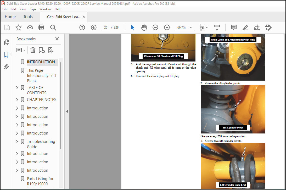
4 Remove the (left or right) oil check and fill plug 26
Chaincase Oil Check and Fill Plug 26
5 Add the required amount of motor oil through the check and fill plug until oil is seen at the plug opening 26
6 Reinstall the check plug and fill plug 26
Grease Fitting Locations 26
1 Grease the hitch latch pin and attachment grease cap pivots 26
Hitch Latch and Attachment Pivot Pins 26
2 Grease the tilt cylinder pivots 26
Tilt Cylinder Pivot 26
1 Grease two lift cylinder pivots 26
Lift Cylinder Base End 26
Lift Cylinder Rod End 27
2 Grease the lift arm pivots 27
Lift Arm Pivot 27
Cooling System Drain Procedure 27
WARNING 27
1 Raise the engine cover and lock open the rear grille 27
2 At the lower left bottom area of the radiator, be sure the remote anti-freeze drain hose is protruding out the rear of the chassis 27
3 Place a catch pan with a capacity of at least 7 0 quarts (6,6 L) underneath the chassis, below the drain hose 27
4 Remove the pressurized radiator cap at the top of the radiator 27
5 Fully open the drain cock of the radiator to drain the anti-freeze 27
Radiator Petcock 27
6 Close the petcock on the radiator when it is finished draining 27
7 For R190 and 1900R Models: Add 6 0 quarts (5,7 L) of a mixture of 50% water and 50% ethylene glycol to the radiator 28
8 For R220, R260, 2200R and 2600R Models: Add 6 8 quarts (6,4 L) of a mixture of 50% water and 50% ethylene glycol to the radiator 28
9 Retighten the pressurized radiator cap 28
1 Raise the engine cover and lock open the rear grille 28
2 Remove the fill cap on the hydraulic reservoir and install a wet/dry Shop•Vac hose into the tube 28
NOTE: 28
3 On the cooler side, remove the top hydraulic hose from its fitting on the oil cooler and plug/cap the hose and cooler port 28
4 Disconnect the tube attached at the hydraulic oil filter and plug/cap the tube and filter port 28
NOTE: 28
5 Turn the vacuum ON to lessen the amount of hydraulic oil leakage for this procedure 28
6 Place a catch pan below the lower cooler connection Unscrew the hose fitting at the lower cooler port and plug/cap the hose fitting Turn the vacuum OFF 28
Lower Cooler Port Hose 28
7 After the oil has drained from the cooler, place plugs/caps in the upper and lower ports, or reinstall the hoses and tube 28
1 Raise the engine cover and lock open the rear grille 28
2 Place a catch pan underneath the chassis, below the lower cooler connection 28
3 At the lower left bottom area of the engine oil cooler, above the radiator drain cock, unscrew the hose fitting on the engine oil cooler port and plug/ cap the hose 28
Engine Oil Cooler Hose 28
4 After the oil has drained from the cooler, place a plug/cap in the lower port, or reinstall the hose to the port 28
NOTE: 28
Introduction 29
Engine Access Cover – Removal and Installation 33
WARNING 33
1 Open the rear grille and lock it open 33
2 Open the engine access cover until the gas springs are completely extended 33
3 If equipped with air conditioning, disconnect the condensor fan electrical connector 33
CAUTION 33
4 If equipped with a pre-cleaner, loosen the hose clamp on the flanged tube coming out of the engine cover and separate the hose from the tube 33
5 Disconnect the two gas springs from the engine access cover by removing the gas spring clips at both ends of the gas springs (HVAC) or by using a small screwdriver to pop the retaining clip off the ball stud on each end 33
6 Remove two nuts securing the engine access cover to the chassis Using a plastic hammer, tap one of the cover bolts out of the chassis just far enough to drop one side of the cover and then pull the other side off its bolt and remove the engine ac 33
7 Re-seat the bolt hammered in the previous step 33
ROPS/FOPS Removal and Installation 35
WARNING 35
1 Remove the engine access cover per the procedure in this chapter 35
2 Disconnect two electrical harnesses at the harness bulkhead, along with other smaller electrical connectors If HVAC equipped, the lines need to be removed too, but the freon must be evacuated and the coolant drained before removing HVAC lines 35
Harness Bulkhead 35
3 Raise the ROPS/FOPS per the procedure in the Safety chapter of this manual 35
4 With the ROPS/FOPS tilted back and locked, attach a hoist so that it is supporting the weight of the ROPS/FOPS 35
Important: 35
WARNING 35
1 Carefully remove the shoulder screw and washer that attaches the gas spring and ROPS/FOPS lock mechanism to the ROPS/FOPS Remove the shoulder screw on the other side too 35
2 On each side, remove the capscrew securing the ROPS/FOPS pivot to the frame 35
3 Lift the ROPS/FOPS off the loader 35
Seat Removal and Installation 36
WARNING 36
1 Remove four nuts from the studs attaching the seat to the seat pan underneath the ROPS/FOPS 36
2 Release the lock mechanism and lower the ROPS/ FOPS 36
3 Slide the seat forward and disconnect the seat switch from the wiring harness 36
4 If there is a three-point restraint seat belt, remove the capscrew and locknut attaching the seat to the restraint belt on the left side 36
5 Lift the seat from the seat pan 36
Seat Slide Replacement 37
1 Remove the seat per the procedure in this chapter 37
2 Remove the four screws attaching the seat slides to the seat 37
Standard Seat 37
Air Suspension Seat 37
3 Replace with new slides using the existing screws 37
Side Console Removal and Installation 37
1 On the outside of the machine, remove four machine screws securing the forward side consoles to the ROPS/FOPS 37
2 Remove one machine screw inside at the front of the console 37
3 Pull the console away from ROPS/FOPS 37
Air Duct Louver Replacement 41
1 Using a thin flat-tipped screwdriver, insert the screwdriver between the face of the louver and the louver’s bezel 41
2 Rotate the screwdriver to lift the face and pop it off the bezel to release the louver 41
3 Pop new louver into existing bezel until a “click” sound indicates it is seated 41
ROPS/FOPS Rear Window Removal and Installation 41
WARNING 41
1 Grab and pull emergency exit tag until the ripcord pulls free of rubber seal 41
2 With an assistant outside the ROPS/FOPS to catch the window, push window outward 41
3 Slowly pull weatherstrip away from window frame 42
Weatherstrip 42
1 Recommended but not required: Mix a solution of 10% liquid dish soap and 90% water in a spray bottle 42
NOTE: 42
L-Hook 42
2 Apply soap solution to window, weatherstrip and metal frame surfaces 42
3 Start at top of window frame and install weatherstrip with the ripcord lip facing inside the ROPS/ FOPS and the glass lip facing out 42
4 Spray soap solution between glass window and inside edge of rear window 42
5 Carefully use the L-hook tool between glass and weatherstrip and work it underneath the glass Lift the glass lip over the weatherstrip Use caution to avoid breaking the glass 42
6 Use the pigtail hook tool to “pull down” the weatherstrip seal on the outside of the ROPS/FOPS to secure the window 42
7 On the inside of the ROPS/FOPS, install the ripcord in the ripcord lip, starting at top of weatherstrip Be sure to have emergency exit tag slipped over the ripcord before performing this step 42
8 Using L-hook tool, secure the ripcord in the ripcord lip by “pulling down” the lip over the cord 42
9 Test the window for security and mating of all seals 42
Restraint Bar Removal and Installation 44
1 Remove two machine screws on the access panel located beneath the restraint bar 44
2 Unplug the restraint bar switch wire from the ROPS/FOPS wire harness 44
3 Underneath the restraint bar, through holes cut in the side console, remove locknuts securing the restraint bar to the side console 44
4 Lift the restraint bar assembly off the console and remove from the ROPS/FOPS 44
5 The arm rest on the other console has two locknuts securing it to the console and can be removed like the restraint bar assembly 44
NOTE: 44
All-Tach® and Power-A-Tach® Hitch Removal and Installation 51
1 Power-A-Tach hitch machines: Using a suitable hoist of adequate capacity and a positive locking mechanism able to support the lift arm or equivalent, raise the lift arm high enough to access the single hydraulic cylinder hose lines on the hitch 51
WARNING 51
2 Power-A-Tach hitch machines: Disconnect the two hydraulic hoses from their fittings on the left side of the lift arm crossmember 51
R190/1900R 51
R220/R260/2200R/2600R 51
NOTE: 51
NOTE: 51
3 Restart the machine, lower the lift arm and slightly extend the two tilt cylinders 51
NOTE: 51
4 Remove two capscrews and locknuts securing the lower tilt cylinder pivot pins While supporting the tilt cylinders, drive the pins out of their mounts 51
5 R190/1900R Models: Using a flat-tip screwdriver, pry the grease cap off the lift arm on both sides 51
6 R220/R260/2200R/2600R Models: Remove three socket-head capscrews securing the grease cap to the hitch pivot and remove the cap 51
7 Remove two capscrews and locknuts securing the hitch to the lift arm, then drive the pivot pins out of the hitch and remove the hitch with the hoist 52
8 Retain two shim washers found between the hitch and lift arm 52
WARNING 52
Lift Arm Removal and Installation 57
1 Lower the lift arm 57
2 Remove the bucket or attachment from the loader 57
3 Remove the hitch (if replacing) per the procedure in this chapter 57
WARNING 57
4 Secure the lift arm with a suitable hoist of adequate capacity and a positive locking mechanism able to support the lift arm or equivalent 57
NOTE: 57
NOTE: 57
5 Disconnect hoses from their tubes at the rear of the lift arm On high-flow units there are additional high-flow hoses and tubes to disconnect on the right side 57
Left Rear Lift Arm Hoses 57
Right Rear Lift Arm Hoses 57
6 Remove a capscrew and locknut securing the rod end of the lift cylinder pivot pin to the lift arm 57
Lift Cylinder Pivot Pin 57
7 While supporting the lift cylinder, remove the lift cylinder pin from the lift arm Repeat for the other side 57
WARNING 57
8 Disconnect tilt cylinder hoses from lift arm crossmember tubes, either on top of or behind the lift arm crossmember 58
R190/1900R 58
R220/R260/2200R/2600R 58
9 Remove both tilt cylinders from the lift arm per the procedure in the Hydraulics System chapter 58
10 R190/1900R Models: Remove two capscrews and locknuts securing a cover plate to the top of the lift arm crossmember 58
11 Remove fastening hardware securing the tilt tubes to the crossmember 58
12 Remove the capscrew and locknut that secures the lift arm pivot pin to the chassis Repeat for the other side 58
13 Drive the lift arm pivot pins out of the chassis 58
WARNING 58
14 If possible, use a hoist to move the lift arm onto a raised platform for better access to hydraulic tubes and fastening hardware 58
15 On the left and right sides of the lift arm, remove the fastening hardware securing the hydraulic tubes to either the side or underneath the lift arm, if necessary 58
R190/1900R 58
R220/R260/2200R/2600R 59
16 R190/1900R Models: Remove the cover plate on the couplers at the front of the lift arm on both sides of the lift arm (if so equipped) 59
17 Disconnect the couplers from their tubes and remove the couplers 59
18 If replacing the lift arm, remove the lift arm support device fastening hardware and remove the support device 59
NOTE: 59
NOTE: 59
Lift Arm Bushing Replacement 60
WARNING 60
1 If replacing the lower lift arm bucket pivot bushings, remove the hitch per the procedure in this chapter 60
2 If replacing lift arm bushings, remove the lift arm per the procedure in this chapter 60
WARNING 60
3 Use a punch to drive out bushings There are four upper lift arm composite bushings (two on each side) and two spring bushings used (one on each side) on the lower lift arm 60
Upper Lift Arm Bushing 60
Lower Lift Arm Bushing 60
4 Clean inside the opening to provide a smooth surface for installation of the new bushings 60
5 Apply Loctite® 680 or equivalent compound to the new lift arm bushings 60
6 Press new bushings into place or use a rubber mallet to drive them into the lift arm or links 60
7 Reinstall the hitch or the lift arm on the loader per the procedures in this chapter 60
Lift Arm Stop Installation and Adjustment 61
NOTE: 61
1 Lower the lift arm and measure the gaps between the stops and the lift arm 61
NOTE: 61
2 Remove the bucket or attachment from the loader Raise the lift arm and engage the lift arm support device as described in the Safety chapter of this manual 61
3 Remove one capscrew securing the rubber stop to the chassis and remove both 61
4 Install shim(s) and reinstall the rubber stop with its capscrew 61
5 Start engine and lower the lift arm Verify the gaps (if any) and repeat this procedure as needed 61
Control Console Removal and Installation 61
WARNING 61
1 Remove the rubber floor mat from the loader 61
2 Remove five capscrews and washers securing the control console assembly to the crossmember underneath 61
3 Push the rubber boots inside the control console openings 61
4 With a hammer and punch on one control handle, remove the roll pin securing the grip and allow the grip to hang 62
5 Carefully lift the control cover assembly up and over the control handles and out of the loader 62
6 Two recessed cutouts in the crossmember allow access to the control handle assemblies 62
1 Remove four screws securing the control handle tower covers on both the left and right control handles 62
2 Before lifting off the tower covers, pull the rubber boots up and over the control handles and remove them 62
3 Lift up and remove the tower covers to access the hydraulic lines in the control handle towers 62
Clean-Out Cover, Floor Plate and Kickplate Cover Removal and Installation 63
WARNING 63
1 Remove the control consoles per the procedure in this chapter, if necessary 63
2 If removing debris from the foot area or to access hydraulic foot pedal hoses on hand/foot loaders, remove three self-tapping screws on the kickplate cover at the front of the chassis 63
Kickplate Cover 63
3 T-Bar, Dual Hand and Dual Joystick Models: Inside the ROPS/FOPS, carefully pull up on and remove the rubber floor mat 63
4 T-Bar, Dual Hand and Dual Joystick Models: Remove three capscrews securing the clean-out plate to the floor plate 63
5 T-Bar, Dual Hand and Dual Joystick Models: Remove the remaining capscrews securing the floor plate to the chassis and carefully remove the floor plate, being sure not to damage the foot pedal throttle 63
6 Hand/Foot Models: Between the foot pedals, remove four locking capscrews securing the clean- out cover (or doghouse cover) and lift it out of the loader 63
7 Hand/Foot Models: Unstrap two hydraulic hose straps (one is bolted just above the bellyplate) and free the hoses from the straps 63
8 Hand/Foot Models: Remove the remaining capscrews securing the floor plate to the chassis and pull the floor plate up from the rear to the front to expose the foot pedal hydraulic lines 63
9 Hand/Foot Models: There are several hoses attached to hydraulic foot valves to disconnect and remove before the floor plate may be removed 64
Hand/Foot Pedal Hoses – Right Side 64
NOTE: 64
NOTE: 64
Crossmember Removal and Installation 64
WARNING 64
1 Remove the control consoles per the procedure in this chapter 64
2 Remove the floor plate per the procedure in this chapter 64
3 Remove three locking capscrews securing the left and right ROPS/FOPS seal plates inside the chassis and remove the plates 64
ROPS/FOPS Seal Plate – Right Side Shown 64
4 Disconnect the wheel drive control handle hoses on top of the hydrostatic pump at their fittings 65
NOTE: 65
NOTE: 65
Cap or plug the hydraulic hoses and fittings after disconnecting them to prevent fluid loss and contamination of the hydraulic system 65
5 Disconnect the lift and tilt control handle hoses where they connect to main control valve or hydraulic tubes or solenoid valve in the chassis 65
At Control Valve 65
At Control Valve 65
At Solenoid Valve 65
6 Disconnect the electrical connector in the control handles at the end of the wire 66
Right Handle Wire Connector 66
7 Remove three torx screws and their spacers securing the crossmember foam cover to the crossmember and lift the foam cover up and out of the loader, over the control handles 66
8 Remove the eight tapping capscrews securing the crossmember to the chassis 66
9 Using two people, carefully lift the crossmember with the control handles attached out of the chassis 66
NOTE: 66
WARNING 66
1 Remove the control console per the procedure in this chapter 66
2 Remove the floor plate per the procedure in this chapter 66
3 Disconnect the electrical connector in both control handles at the end of the wire 66
4 Disconnect the clevis assemblies on the lift and tilt control rods from the main control valve 66
5 Disconnect the rod ends of the wheel drive control rods from the pivot tube assembly underneath the crossmember 67
6 Remove the eight tapping capscrews securing the crossmember to the chassis 67
7 Using two people, carefully lift the crossmember with the control handles attached out of the chassis 67
NOTE: 67
Hydraulic Oil Reservoir Removal and Installation 67
WARNING 67
IMPORTANT: 67
1 Remove the lift arm per the procedure in this chapter 67
1 Drain all the oil from the hydraulic reservoir into a suitable container capable of holding at least 11 to 12 gallons (41,6 to 45,4 L) For this procedure refer to the procedure in the Lubrication chapter 67
2 After removal of the hydraulic oil from the reservoir, remove the visual sight gauge and oil fill tube from the tank 67
Visual Hydraulic Oil Level Indicator 67
3 Disconnect three hydraulic hoses from the reservoir near the bottom of the reservoir 68
4 Unbolt the plate at the top of the reservoir to reveal a welded lifting hook 68
5 Using a suitable hoist with a locking hook of adequate capacity and a positive locking mechanism able to support the reservoir or equivalent, hook the reservoir lifting hook and slowly lift the hydraulic reservoir up and out of the loader 68
NOTE: 68
1 Install hydraulic reservoir drain plug and refill with correct type of hydraulic oil Refer to Lubrication chapter for hydraulic oil specifications 68
2 ALWAYS check for hydraulic fluid leaks after reassembling any component of the hydraulic system 68
WARNING 68
WARNING 68
Fuel Sensor Removal and Installation 68
WARNING 68
1 Drain fuel tank into a clean approved container Drain fuel below the sensor mounting 68
2 Disconnect the two wires from the sensor, or unplug the sensor connector 69
3 Remove the remaining screws securing the sensor, then remove the sensor and gasket from the tank 69
4 R190/R220/1900R/2200R Models with Deutsch connector on fuel sensor: Support the lift arm with a suitable hoist of adequate capacity and a positive locking mechanism able to support the lift arm or equivalent Remove the capscrew and locknut that s 69
5 Drive the lift arm pivot pins out and move the lift arm forward enough to remove the fuel sensor with the Deutsch connector out of the fuel tank 69
1 Clean old gasket adhesive off fuel tank 69
2 Install new gasket using Form-A-Gasket #765- 1211 (or equivalent) to seal sensor opening on fuel tank 69
3 With the float to the rear of the fuel tank, install the sensor in the fuel tank 69
4 Install five of the six screws through the sensor into the fuel tank DO NOT OVERTIGHTEN 69
5 Attach #25 (brown) wire to center stud with a nut, and #0 (black) wire to ground stud with the fifth screw, or, if so equipped, reconnect the Deutsch connector to the harness 69
Rear Grille Removal and Installation 69
WARNING 69
1 Open the engine access cover, pull up on the rear grille latch and swing the rear grille fully open to its locked-in position 69
2 Disconnect the tail lights wire harness (and backup alarm harness, if so equipped) along the right side of the engine compartment and remove any securing cable ties 69
3 Support the rear grille with a suitable hoist of adequate capacity and a positive locking mechanism able to support the rear grille or equivalent 70
4 Remove two cotter pins on two clevis pins fastening the rear grille to the chassis 70
5 Using the hoist, remove the rear grille from the chassis 70
Rear Grille Latch Removal and Installation 70
1 Open the engine access cover, pull up on the rear grille latch and swing the rear grille fully open to its locked-in position 70
2 Remove two carriage bolts and locknuts securing the latch to the rear grille 70
3 Remove the door latch from the rear grille 70
Introduction 71
Drive Chain Adjustment 73
WARNING 73
1 Remove the wheels and tires on the side of the loader to be serviced 73
2 Remove 14 machine screws on the chaincase access cover (between tires) to access the drive chain 73
3 Drain the oil from the chaincase See the procedure in the Lubrication chapter 73
4 Correct chain deflection is ½” @ 20 lbs force (13 mm @ 89 N) – midway between the sprockets 73
5 To adjust chain tension, loosen the eight locknuts on the two axles on one side of the loader Using a spreader bar, push the axles outward in their slots to tighten the chain 73
6 After the proper chain tension is obtained, retighten the locknuts on the axle Axle housing locknuts should be torqued to 280 lbf-ft (380 N•m) 73
IMPORTANT: 73
7 Scrape off the old oil-resistant RTV and apply new RTV Reinstall the access cover 73
8 Refill the oil in the chaincase See the procedure in the Lubrication chapter 73
9 Reinstall the wheels and tires Wheel nut torque is: 180 ft -lbs (244 N•m) 73
10 Repeat the adjustment procedure for the other side 73
Axle Housing Assembly Removal and Installation 74
WARNING 74
1 Remove the wheels and tires on the side of loader being serviced 74
2 Drain the oil from the chaincase See the procedure in the Lubrication chapter 74
3 Remove 14 machine screws on the chaincase access cover (between tires) to access the drive chain 74
4 Attach a suitable hoist of adequate capacity and a positive locking mechanism able to support the axle assembly or equivalent to the axle assembly Remove the eight locknuts and washers attaching the axle housing to the chassis 74
5 Pull axle housing away from the chassis, allowing the axle housing sprocket to drop inside the chaincase 74
NOTE: 74
1 Support the axle housing assembly with a suitable hoist of adequate capacity and a positive locking mechanism able to support the axle housing assembly or equivalent 75
2 Clean the side of the chassis where installing 75
3 Place a bead of grease in the o-ring channel on the axle and install a new o-ring on the axle housing assembly 75
4 Align the holes in the axle housing with studs in the chassis and push it in place 75
5 Install the eight washers and locknuts securing axle housing to chassis (hand tighten at this point) 75
6 Install and adjust the drive chains per the procedure in this chapter Axle nut torque is 280 lbf-ft (380 N•m) 75
7 Reinstall the chaincase access cover using oil- resistant RTV sealant between cover and chaincase 75
8 Refill the oil in the chaincase See the procedure in the Lubrication chapter 75
9 Reinstall the wheels and tires Wheel nut torque is: 180 ft -lbs (244 N•m) 75
Drive Chain Removal and Installation 78
WARNING 78
1 Remove the wheels and tires on the side of the loader being serviced 78
2 Drain the oil from the chaincase See the procedure in the Lubrication chapter 78
3 Remove 14 machine screws on the chaincase access cover (between tires) to access the drive chain 78
4 For each drive chain: Loosen the eight locknuts on axle assembly attached to the chain Slide the axle assembly in its slots to loosen the chain tension 78
5 Supporting the axle with a suitable hoist of adequate capacity and a positive locking mechanism able to support the axle or equivalent, pull the axle housing out of the chaincase to allow the axle housing sprocket to drop inside the chaincase 78
6 Slip the drive chain off the axle housing sprocket Then, slip the drive chain off the drive motor sprocket 78
7 Remove the drive chain from the chaincase 78
NOTE: 78
1 Wrap the chain around sprocket of the axle 78
2 Wrap the chain around the drive motor sprocket 78
3 Adjust the drive chain to the proper tension per the “Drive Chain Adjustment” procedure in this chapter 78
1 Drain the oil from the chaincase See the procedure in the Lubrication chapter 78
2 Remove 14 machine screws on the chaincase access cover (between tires) to access the drive chain 78
3 Rotate the tires to access the connecting link 78
4 Remove two cotter pins securing the connecting link to the drive chain and disconnect the link 78
5 Slip the drive chain off the axle housing sprocket Then, slip the drive chain off the drive motor sprocket 78
6 Remove the drive chain from the chaincase 78
*NOTE: 78
Axle and Wheel Bearing Disassembly and Assembly 79
1 Move axle housing assembly to a workbench and clamp it in a vise Use caution not to clamp cast web members in a way that they might be damaged 79
2 Using a retaining ring pliers, remove external retaining ring and washers from axle shaft 79
3 Remove the inner bearing cup and cone from axle shaft 79
4 Remove axle from axle housing 79
5 Remove the axle seal from the axle housing 79
6 Remove the inner bearing cone from axle shaft 79
7 Turn housing assembly over and remove the inner bearing cup from the axle housing assembly 79
8 Thoroughly clean/flush all the disassembled parts 79
NOTE: 79
1 Install the bearing cup in the axle housing with a force of 6000 lbf-ft (26,7 kN) using a bearing press 79
2 Install the double-lip axle seal (do not crush) in the axle housing, until it is flush with the surface of the axle housing 79
3 Turn the axle housing over and press an additional bearing cup into the other side of the axle housing with a force of 6000 lbf-ft (26,7 kN) using a bearing press 79
4 Place the axle shaft on a flat surface with the shaft in a vertical position Press the inner bearing cone onto the axle shaft with a suitable driver or a press at a force of 6000 lbf-ft (26,7 kN) Note the proper orientation of the first bearing 80
5 Insert axle housing onto axle shaft 80
6 Press another inner bearing cone onto the axle shaft Note the proper orientation of the second inner bearing cone 80
7 Spread the bearing grease around the cone surface 80
8 Place a bead of grease in the o-ring channel on the axle and install a new o-ring on the axle housing assembly 80
9 Install the special washer(s) and the retaining ring 81
NOTE: 81
10 Seat the external retaining ring in axle shaft groove 81
Introduction 83
5 84
11, 13 84
4, 12, 14 84
4, 12, 14 84
1, 7, 10 84
2, 3, 6, 8, 9 84
2 84
3 84
Dual Joystick, Dual Hand Controls 84
Hand/Foot Controls 84
5 84
1, 6, 8, 9 84
11, 13 84
1, 7, 10 84
1, 7, 10 84
4, 12, 14 84
11, 13 84
T-Bar Controls 84
2, 3, 6, 8, 9 84
Control Handle Assembly (Both Control Handles) Removal and Installation 92
1 Remove the crossmember per the procedure in the Mainframe chapter 92
2 Disassemble the control handles on a workbench to replace parts as needed 92
Control Handle Removal and Installation – Electrical Auxiliary Grip – Dual Joystick, Dual Hand and Hand/Foot Controls 92
WARNING 92
1 Loosen the ratchet handle on the lift/tilt joystick tower and tilt the right control handle forward 92
2 Pull the joystick boot up and off the joystick 92
3 Remove screws securing the tower cover to the tower and remove the cover 92
Ratchet Handle 92
4 Disconnect the electrical connector in the control handle at the end of the wire Note the wire terminal connections for assembling the control handle if replacing the handle’s electrical cable 92
Right Handle Wire 92
5 Dual Joystick/Dual Hand Units: Remove six hoses attached at the bottom of the joystick tower Mark the hoses with their corresponding port numbers for reinstallation 92
6 Hand/Foot Units: Remove four hoses attached to the single-axis control valve below the joystick tower Mark the hoses with their corresponding port numbers for reinstallation 93
Single-Axis Control Valve 93
7 Dual Joystick/Dual Hand Units: Remove four self- tapping thread screws securing the joystick to the drive stand 93
8 Hand/Foot Units: Remove two self-tapping thread screws securing the joystick to the joystick tower 93
9 Pull the disconnected hoses down and out of the joystick tower 93
10 Pull the joystick up and out of the joystick tower and set the drive on top of the tower Loosen the locking hex nut and unscrew the grip from the joystick 93
Locking Hex Nut 93
11 Pull the connector out of the joystick tower 93
12 Remove the grip from the skid-steer loader 93
Control Handle Removal and Installation – T-Bar Controls 94
WARNING 94
1 Remove the control console per the procedure in the Mainframe chapter 94
2 Disconnect the electrical connector in both control handles at the end of the wire Note the wire terminal connections for assembling the control handle if replacing the handle’s electrical cable 94
3 Remove the locknuts to disconnect the studded rod ends on the control rods from the control handle assemblies 94
4 Remove capscrews, washers and locknuts on the elastomeric rod ends attaching the control handle assemblies to the crossmember Remove the handle assembly 94
NOTE: 94
T-Bar Control Handle Assembly 95
NOTE: 95
1 Slide the T-Bar boot up the T-Bar control handle 95
2 Attach elastomeric rod ends to sides of pivot with capscrews, washers and locknuts 95
Elastomeric Rod Ends 95
3 Press or drive two bronze bearings into holes on pivot Use a bearing driver, if available 95
4 Thread the four (left side) or eight (right side) electrical wire terminals in the control grip through a hole at the top of the control handle 95
5 Place a small rubber cap over the ends of the electrical wires and feed it into a hole leading inside the control handle 95
6 Install the left control grip at the top of the control handle aligning the hole in the grip with the hole in the handle 96
NOTE: 96
7 Insert roll pin through the aligned holes to secure the left handle grip to the control handle 96
8 Place top half of pivot and two washers on control handle, then slide handle through pivot 96
9 Place T-Bar stop between washers: 96
Capscrew 96
10 Insert the four and eight wire terminals into their corresponding electrical connector housings 97
Four-pin Connector 97
Eight-pin Connector 97
11 Press an orange wedge into the other ends of the connector housings 97
Dual Joystick, Dual Hand and Hand/Foot Control Handle Assembly 97
1 Using a rubber mallet, hammer two bronze bearings into the lower portion of the joystick tower 97
2 Insert the tilt console pin into the bronze bearings and secure with external retaining rings 98
3 Attach the ratchet handle to the joystick tower with a flat washer and carriage bolt 98
4 Screw six adapters into the bottom of the joystick There are four smaller of one size and two larger of another size Consult the illustrations in this manual or the parts manual for correct installation of these adapters 98
5 Screw down and attach the control grip to the top of the joystick 98
6 Route the electrical wire in the control grip through a slot in the joystick 98
7 Slip the entire assembly into the joystick stand 98
8 Bolt the joystick onto the joystick stand 98
9 View of joystick secured onto the joystick stand 99
10 Connect the tower cover to the joystick stand with four machine screw 99
11 Pull the boot down over the control grip and top of the joystick stand 99
12 View of correctly orientated control handles 99
Pivot Tube Removal and Installation, Disassembly and Assembly – T-Bar Controls 99
WARNING 99
1 Remove the crossmember per the procedure in the Mainframe chapter 99
NOTE: 99
2 Disassemble the pivot tube assembly on a workbench to replace parts as needed 99
3 Remove two locknuts securing rod end studs on the pivot tube arms and remove studs/control rods from the arms 99
4 Remove one hex nut on each centering device 100
5 Remove four capscrews securing the pivot tube control mount to the crossmember 100
6 Slip both pivot brackets off the ends of the control pivot shaft and remove the pivot assembly 100
Roll Pin 100
7 A bronze bearing is pressed into both pivot brackets, remove them from their brackets 100
8 Remove two roll pins in the pivots and slide all pivots and washers off the shaft Bronze bearings are pressed onto the control pivot shaft, remove them from the shaft 100
NOTE: 100
NOTE: 100
Control Handle Position Adjustment – T- Bar Controls 101
WARNING 101
1 Left Control Handle: Adjust two control rod lengths connected at the pivot assembly, so that the bracket on the pivot assembly is oriented 90° to the chassis 101
2 Left Control Handle Vertical Orientation: Adjust two control rod lengths connect at the pivot assembly to realize a 8° forward tilt to the handle 101
3 Right Control Handle Vertical Orientation: Adjust lift control rod length attached to bottom of pivot assembly to realize a 8° forward tilt to the handle 101
4 Right Control Handle Orientation: Adjust the tilt control rod length until it is oriented 90° to the chassis BE SURE the adjustment allows for full activation of the control valve in both directions of handle operation 101
5 Reference the illustration on the previous page for additional clarification 101
Control Handle Tracking Adjustment 101
WARNING 101
1 Decide which side needs to be adjusted If the loader turns right while going FORWARD, the left side speed must be reduced, and vice versa DO NOT attempt to increase speed of either side, because it may damage the hydrostatic pump 101
FORWARD Adjusters 101
NOTE 101
2 If the loader turns right in FORWARD position, remove a front plastic cap on the hydrostatic pump with pliers Use an allen wrench to hold the stud in place while loosening the locknut With the allen wrench in clockwise motion, tighten 1/4 turn 102
3 If the loader turns right in REVERSE position, use the adjustment points opposite the FORWARD position adjustment points in step 2 102
REVERSE Adjusters 102
4 If the loader turns left in FORWARD position, remove a rear plastic cap on the hydrostatic pump with pliers Use an allen wrench to hold the stud in place while loosening the locknut With the allen wrench in clockwise motion, tighten 1/4 turn Re 102
5 If loader turns left in REVERSE position, use the adjustment points opposite the FORWARD position adjustment points in step 4 102
6 Lower and secure ROPS/FOPS Start the loader Test loader tracking; repeat the adjustment as needed 102
WARNING 102
1 Decide which capscrew to adjust If the loader turns right, the left side speed must be reduced and vice versa DO NOT attempt to increase the speed of either side, it may cause the control arm assemblies to overtravel, resulting in damage to the 102
2 If the loader is turning right, loosen the locknuts on the left, top and bottom capscrews In a counterclockwise motion, unscrew the capscrew 1/2 turn and retighten the nuts 102
3 If the loader is turning left, loosen the locknuts on the right, top and bottom capscrews In a counterclockwise motion, unscrew the capscrews 1/2 turn and retighten the nuts 102
4 Lower and secure the ROPS/FOPS Start the loader Test loader tracking, repeat adjustments as needed After correct adjustment, reinstall the control consoles 102
Neutral Centering Test and Adjustment 103
WARNING 103
1 Mark and disconnect the pilot lines going into the top of the pump for the section being tested 103
2 Plug the end of the hoses Do not cap the fittings on the transmission 103
3 Disconnect the drive hoses from the section being tested 103
4 Plug the drive hoses and cap the fittings on the transmission 103
5 Connect X1 and X2 ports together by means of 1/4” internal diameter hose or tubing 103
X1 103
6 Install 8702 psi (600 bar) pressure gauges in MA and MB of the section being tested 103
7 Block ports A and B ports blocked (or apply the parking brake) 103
8 Start the machine observing safety practices 103
9 Loosen the jam nuts on the neutral adjustment screws 103
10 Turn the mechanical centering adjusting screw until 1000 psi (70 bar) is read on the pressure ports 103
11 Turn the screw back, splitting the distance between the previous two positions 103
Note: 103
12 Tighten the jam nut on the adjustment screws when equal pressure is measured on both gauges 103
13 Stop the pump drive 103
14 Remove the hose connecting ports X1 and X2 Reinstall plugs where MA and MB were checked 103
15 Adjust NEUTRAL in the other section, if necessary 103
WARNING 104
1 Remove one hex nut on each rod end attached to the hydrostatic control arms 104
NOTE: 104
2 Twist the rod ends on the control rods until they slip over the capscrew and spacer without the control arms or centering devices moving Tighten the rod ends to the control arms and then the jam hex nuts to the rod ends 104
3 Test the operation of the control handle, push the control handle forward and backward and allow the centering devices to return the control handle to the NEUTRAL position 104
IMPORTANT 104
Lift/Tilt Control Removal and Installation 105
WARNING 105
1 Remove the floor plate and kickplate cover per the procedure in the Mainframe chapter 105
2 Mark the hydraulic hoses prior to disconnecting them for easier re-assembly 105
IMPORTANT: 105
3 Either through the kickplate cover at the front of the machine or through removal of the floor plate, disconnect six hydraulic hoses, three on each foot valve 105
Hand/Foot Pedal Hoses – Right Side 105
Hand/Foot Pedal Hoses – Left Side 105
Hand/Foot Pedal Hoses 105
4 Lift foot pedal assembly out of chassis 105
5 If needed, remove two capscrews securing each foot pedal to its foot valve 105
6 If replacing a foot valve, mark and remove connecting hydraulic tubing and four capscrews on each foot valve securing them to the floor plate 105
7 To reassemble, refer to the exploded view near the front of this chapter as a guide 105
WARNING 106
1 Disconnect four hydraulic pressure hoses from the control valve, two in the rear and two in front 106
IMPORTANT: 106
2 Disconnect two hydraulic hoses from the solenoid located above the control valve and at the front of a hydraulic tube running below the control valve 106
WARNING 107
1 Remove the control console per the procedure in the Mainframe chapter 107
2 Disconnect the clevis assembly on the lift control rod from the main control valve 107
3 Disconnect the clevis assembly on the tilt control rod from the main control valve 107
4 Disconnect the electrical connector at the bottom of each control handle 107
5 Remove two capscrews, washers and locknuts securing the T-Bar pivot to two elastomeric rod ends at the front of the crossmember 107
6 Pull the control handle assembly forward and out 107
Lift/Tilt Control Adjustment – T-Bar Controls 107
WARNING 107
1 The lengths of the lift and tilt control rods can be adjusted to obtain proper position of the T-Bars Refer to the “Control Handle Position Adjustment” procedure in this chapter 107
2 The “Self-Leveling Valve Adjustment” procedure in the Hydraulic System chapter is also related to correct operation of the lift and tilt controls Refer to this procedure as needed 107
Electrical Foot Throttle Removal and Installation – T-Bar, Dual Hand and Dual Joystick Controls 109
WARNING 109
1 Remove two swell latches on the right side panel inside the cab located at the operator’s knee 109
2 Unplug the electrical connector on the electric foot throttle 109
3 Remove two carriage bolts and locknuts securing the foot throttle assembly to the front chassis plate 109
4 Remove the entire electric foot throttle assembly from the skid-steer loader 109
Introduction 111
Charge Pressure Test and Adjustment 119
NOTE: 119
WARNING 119
1 Locate the test port near the brake valve 119
Charge Pressure Test Port 119
High Pressure Relief Valves – T-Bar 119
Charge Relief Valve – DJS, DH & H/F 119
2 Remove the metal cap from the test port (ISO 15171-2, coupling with M16x2 end for connections under pressure ) 119
3 Install a pressure gauge on the charge pressure test port 119
4 Restart the engine and allow it to run until the hydraulic oil is at operating temperature, around 140° F (60° C) and check the pressure reading on the gauge The gauge should read as follows: 119
5 If the pressure reading on the gauge is either lower or higher than specified, refer to the manufacturer’s service manual for the hydrostatic pump and the charge pressure adjustment procedure that follows 119
6 When finished, reinstall the metal cap on the test port 119
Hydrostatic Pump Relief Valves 120
Hand/Foot, Dual Hand & Dual Joystick Pump 120
T-Bar Pump 120
Hydrostatic Pump Removal and Installation 120
WARNING 120
1 Drain the oil from the hydraulic reservoir per the procedure in the Lubrication chapter 120
2 Remove the control console, floor plate and crossmember per their procedures in the Mainframe chapter 120
3 Remove the auxiliary pump per the procedures in the Hydraulic System chapter 120
IMPORTANT: 120
4 Pilot Controls: Label and disconnect all the hydraulic hoses and tubes from their fittings connected to the hydrostatic pump 120
5 Servo Controls: Disconnect the control rods attached to pump control arms at the top of the hydrostatic pump 121
6 Position a hoist above the hydrostatic pump Attach lifting straps around the pump and raise the hoist to remove slack from the strap/hook The hoist should now support the weight of the pump 121
7 Remove the two capscrews (55 lbf-ft) (74,6 N•m) and washers securing the hydrostatic pump to the flywheel housing Use Loctite™ 242 or equivalent to reinstall 121
8 Shift the hydrostatic pump forward to disengage the splined shaft drive of the pump 121
9 Lift and maneuver the hydrostatic pump out of the skid-steer loader 121
10 If necessary, remove the splined coupler from the pump Remove two socket-head screws (25 lbf-ft) (34 N•m) on the coupler and slip it off the pump shaft Before doing so, measure the distance (0 39 – 0 42”) (9,9 – 10,6 mm) between the face of 121
Measure This Distance 121
Hydrostatic Pump Drive Coupling Removal and Installation 122
WARNING 122
1 Remove the hydrostatic pump per the procedure in this chapter 122
2 Remove eleven socket-head capscrews (39 lbf-ft) (52,8 N•m) securing the flywheel housing to the engine Use Loctite™ 242 or equivalent to reinstall 122
3 Remove the eight capscrews (39 lbf-ft) (52,8 N•m) attaching the flexible coupling plate to the engine Use Loctite™ 242 or equivalent to reinstall 122
4 Do not apply any lubrication or grease to the flexible coupling plate when reinstalling The leading edge of the coupler hub is to be positioned 0 39”- 0 42” (9,9 mm – 10,6 mm) from the surface of the hydrostatic pump Torque the set screws on 122
Drive Motor Removal and Installation 123
WARNING 123
1 Underneath the skid-steer loader, remove capscrews securing the belly pan and a chassis cover and then remove both pans from the chassis 123
2 Remove the drive chains per the procedure in the Wheel Drives chapter 123
3 If necessary, drain oil from the hydraulic reservoir and chaincases per their procedures in the Lubrication chapter 123
NOTE: 123
4 BEFORE disconnecting hydraulic hoses and tubes from the drive motor, mark each hose/tube and the port where it attaches to the drive motor (so that hoses/tubes can be correctly reattached during installation) 123
5 Disconnect all hydraulic hoses and tubes on each drive motor 123
Right Drive Motor – T-Bar 123
Left Drive Motor – T-Bar 123
Right Drive Motor – DJS, DH & H/F 123
Left Drive Motor – DJS, DH & H/F 124
6 Support the drive motor with a suitable hoist of adequate capacity and a positive locking mechanism able to support the drive motor or equivalent and remove six socket-head capscrews (200 lbf-ft) (271 N•m) and washers attaching the drive motor t 124
7 Carefully lower the drive motor through the belly opening and out of the chassis 124
NOTE: 124
Hydrostatic/Hydraulic Schematic – Hand/Foot Controls 130
Hydrostatic/Hydraulic Schematic – Dual Joystick/Dual Hand Controls 129
Troubleshooting Guide 125
Hydrostatic/Hydraulic Schematic – T-Bar Controls 131
Pressure Check, Test and Adjustment 176
Standard Auxiliary Couplers – R190/1900R 176
1 At the Hydraulics Couplers: Climb into the operator’s seat, lower the restraint bar and start the engine 176
2 Activate the standard control function of the standard auxiliary, or high-flow auxiliary if checking that 176
3 Slowly increase the engine speed to high idle 176
4 Have assistant observe the pressure reading on the gauge The pressure reading on the loader should be: 176
5 If the pressure reading is NOT between the specified pressures, adjust the pressure as follows 176
WARNING 176
NOTE: 176
6 Remove the cap(s) on the relief valve adjuster screw(s) The high-flow auxiliary relief valve is located at the top rear of the control valve The standard auxiliary relief is beneath the high-flow relief at the bottom rear of the control valve 176
High-Flow Auxiliary Relief Valve 176
Standard Auxiliary Relief Valve 177
7 With an assistant’s help, set the engine to high idle, actuate the auxiliary function and monitor the pressure on the gauge 177
8 With a flat-edge screwdriver, turn the adjuster screw IN to increase pressure or OUT to reduce pressure 177
Adjuster Screw 177
9 After the pressure is within the correct PSI (bar) range, replace the cap over the adjuster screw 177
10 If, after adjustment, there is NO CHANGE in the pressure reading, this indicates either a defective auxiliary pump or relief valve cartridge (on the control valve) To determine which is the cause, first replace the relief valve cartridge If the 177
Tilt Cylinder Test 177
NOTE: 177
WARNING 177
IMPORTANT: 177
1 Checking one tilt cylinder at a time, remove the upper hydraulic hose from the cylinder being tested, and cap or plug the hose Caps/plugs MUST BE able to withstand full hydraulic pressure 177
2 Install an extra hose to the upper cylinder port and place the other end of this hose into an empty bucket 178
3 Climb back into the operator’s seat, lower the restraint bar, and start the engine Have an assistant watch the hose in the bucket 178
4 Slowly actuate the roll back (curl) function of the hitch If oil streams into the bucket, the cylinder seals are malfunctioning Replace the cylinder seals 178
5 After the tilt cylinder has been tested, be sure to reconnect the tilt cylinder hydraulic hose removed in step 1 178
6 Repeat steps 1 – 5 for the other side 178
Tilt Circuit Spool Leakage Test 178
WARNING 178
1 Required Equipment: Pressure Gauge (0-5000 psi) (345 bar), infrared thermometer, two people, tape measure or caliper, stop watch 178
2 Install the pressure gauge into the hydraulic circuit of the rod end of the tilt cylinder The gauge can be installed anywhere between the cylinder and the control valve 178
3 Idle the machine until the hydraulic oil is stabilized at 120° F (49° C) The oil temperature can be determined by using the infrared thermometer The temperature area of the cooler is shown below Once the temperature of the cooler has not vari 178
4 Attach a dirt/construction bucket to the machine Position the bucket so that approximately 0 5″ (12,7 mm) of the rod is exposed 178
5 Add weight to the bucket until the pressure gauge reads 1400-1500 psi (96,5 – 103 bar) 178
6 Roll back the bucket fully Find a position that can be easily measured between the barrel of the cylinder and the rod Record this dimension 178
WARNING 178
7 Shut the machine off Have the operator turn the key to the ON position and remain in the seat with the restraint bar down (This is done to ensure the additional hydraulic locks remain open for the test period) 178
8 Begin recording time on the stop watch 178
9 After a period of ten minutes, record the amount that the cylinder had moved 178
10 Compare to the allowable movement of 0 88” (22,3 mm) of cylinder movement for R260/2600R models, and 1 07” (27,1 mm) for R190/R220//1900R/2200R models in a 10 minute period This is the highest allowable leakage value per the valve manufactur 178
Self-Leveling Valve Test 179
WARNING 179
1 With the engine OFF and the ROPS raised and locked, remove the plastic cap and loosen the jam nut on the self-leveling valve adjuster screw 179
Self-Leveling Valve Adjuster Screw 179
NOTE: 179
2 With an allen wrench, turn the adjuster screw in (clockwise) until it bottoms out The self-leveling valve is now disabled and will not affect the tilt operations 179
3 Perform steps 3-5 in the “Tilt Cylinder Test” procedure If the bucket no longer drifts, the self-leveling valve is defective If the bucket continues to drift, the control valve is defective and in need of repair or replacement 179
4 Refer to the “Self-Leveling Valve Adjustment” procedure in this chapter for correct adjustment of the self-leveling valve 179
Lift Cylinder Test 179
NOTE: 179
WARNING 179
1 Remove the clamp securing the hydraulic tubes to the lift cylinder on the side being tested 179
IMPORTANT: 179
2 Disconnect the hydraulic tube from the rod end port of the lift cylinder to be tested 179
3 Install a plug on the hydraulic tube Attach a hose to the rod end port of the cylinder and run the other end of the hose into a suitable container 180
4 Climb into the operator’s seat, lower the restraint bar and start the engine 180
5 Hold the lift control in the RAISE position to extend both cylinders (a small amount of oil will exit the hose initially) If the seals in the cylinder are defective and leaking, oil will flow out of the rod end port 180
6 Slowly lower the lift arm until the support device contacts the lift cylinder Shut off the engine and relieve hydraulic pressure with the lift control 180
7 Reconnect the tube to the cylinder, then reattach the clamp around the hydraulic tube and cylinder 180
8 The other cylinder can be checked the same way 180
NOTE: 180
9 Relieve hydraulic pressure Disconnect the ride control tubes to port A & B of the ride control manifold Cap the fittings on the hydraulic tubes 180
10 Raise the lift arm, engaging the lift arm support device, and check for drifting 180
11 With an operator in the seat, the keyswitch set to the ON position and the restraint bar lowered, check to see if drifting has subsided, if so, then the solenoid valve nearest port A of the ride control manifold should be replaced 180
12 If drifting remains after disconnecting the ride control manifold, then the control valve is at fault and should be replaced 180
Lift Circuit Spool Leakage Test 180
WARNING 180
1 Required Equipment: Pressure Gauge (0-5000 psi) (345 bar), infrared thermometer, two people, Tape measure or caliper, stop watch 180
2 Install the pressure gauge into the hydraulic circuit of the base end of the lift cylinder The gauge can be installed anywhere between the cylinder and the control valve 180
3 Idle the machine until the hydraulic oil is stabilized at 120° F (49° C) The oil temperature can be determined by using the infrared thermometer The temperature area of the cooler is shown below Once the temperature of the cooler has not vari 180
4 Attach a bucket to the machine Position the bucket so that 5 00″-6 00” (127 – 152 mm) of rod is exposed 180
5 Add weight to the bucket until the pressure gauge reads 1400-1500 psi (96,5 – 103 bar) 181
6 Roll back the bucket fully and raise the lift arm so that 5 00″-6 00” (127 – 152 mm) of the rod is exposed Find a position that can be easily measured between the barrel of the cylinder and the rod Record this dimension 181
WARNING 181
7 Shut the machine off Have the operator turn the key to the ON position and remain in the seat with the restraint bar down (This is done to ensure the additional hydraulic locks remain open for the test period) 181
8 Begin recording time on the stop watch 181
9 After a period of ten minutes, record the amount that the cylinder had moved 181
10 Compare to the allowable movement of 0 62” (15,7 mm) of cylinder movement for R260/2600R models, and 0 75” (19 mm) for R190/R220//1900R/2200R models in a 10 minute period This is the highest allowable leakage value per the valve manufacturer 181
Solenoid Valve Test – Lift Arm Pilot Supply, Joystick Drive Supply, Power-A-Tach, Brake/Two-Speed, Safety Locks and Ride Control 181
1 Climb into the operator’s seat, lower the restraint bar and start the engine 181
2 BE SURE the parking brake switch on the instrument panel is in the OFF position 181
3 Raise the restraint bar Operate the drive controls (one at a time) to see if the tires will move If the skid loader moves forward or backward, the system is malfunctioning Possible causes for the malfunction include, but are not limited to: 181
Brake/Two-Speed 181
Lift Arm Pilot Supply 182
Tilt Lock 182
Power-A-Tach 182
4 If any solenoid in the tests appears to be malfunctioning, test the solenoid coil(s) as follows: 182
WARNING 182
5 For service procedures, refer to “Solenoid Valve Removal and Installation/Disassembly and Reassembly” procedure in this chapter 182
1 Climb into the operator’s seat, lower the restraint bar and start the engine 183
1 Clear the area of bystanders and raise the lift arm half way up 183
2 Actuate the ride control button on the right control handle If the solenoid is functioning properly, there should be a slight (minimal) drop in the lift arm height and a light in the instrument panel should illuminate 183
Hydraglide™ Solenoid 183
3 Lower the lift arm 183
4 If the Hydraglide™ solenoid valve in the test appears to be malfunctioning, test the solenoid coils as follows: 183
WARNING 183
5 Lower the restraint bar, turn the keyswitch to ON (DO NOT start the engine) Compress the operator’s seat and hold to temporarily bypass the interlock safety system 183
6 Actuate the Hydraglide™ button to see if the coil magnetizes 183
7 Have an assistant do the metal ruler test: 183
8 For service procedures, refer to “Solenoid Valve Removal and Installation/Disassembly and Reassembly” procedure in this chapter and the Electrical System chapter Troubleshooting Guide Also look at the module test procedures and LED truth tabl 183
Hydraulic Oil Filter Element Replacement 184
NOTE: 184
WARNING 184
1 Open the engine access cover and lock open the rear grille 184
2 Clean any dirt/debris off the surface of the filter housing 184
3 Remove the hydraulic reservoir drain plug from the bottom of the reservoir in the right riser and drain the oil (into a suitable container) to a level below the point where the filter attaches to the reservoir Use an allen wrench to remove the plug 184
Hydraulic Oil Drain 184
4 Reinstall the drain plug 184
5 Using a filter wrench, turn the filter element counterclockwise to remove it from the filter head 184
6 Install the new filter element Before installation, apply a light coat of oil to the gasket and then install it on the filter head 184
7 Hand-tighten the element until the gasket contacts the filter head Turn the element another 3/4 turn to seat the gasket 184
8 Refill the hydraulic reservoir Refer to the Lubrication chapter in this manual for the hydraulic fluid requirements and specifications 184
WARNING 184
WARNING 184
9 ALWAYS check for hydraulic fluid leaks after reassembling components of the hydraulic system 184
Tilt Cylinder Removal and Installation 187
NOTE: 187
1 Remove the bucket or attachment 187
2 With the engine running, lower the lift arm until it is in contact (or near contact) with the lift arm stops (on front of chassis) 187
WARNING 187
3 Disconnect the upper and lower tilt cylinder hoses from the tubes on the crossmember BE SURE to plug the hoses and cap the fittings to prevent fluid loss and contamination of the hydraulic system 187
4 While supporting the weight of the tilt cylinder, remove the capscrew and locknut securing the lower tilt cylinder pivot pin Then drive the pivot pin out to release the lower end of the tilt cylinder 187
5 R190/1900R Models: Loosen the capscrew on the end of the upper tilt cylinder pin by two to three counterclockwise turns Strike the bolt head to drive the pin into the lift arm and break the pin free of the taper Remove the capscrew and flat wash 187
6 R220/R260/2200R/2600R Models: Remove the capscrew and locknut securing the upper tilt cylinder pin Strike the pin to drive it into the lift arm and out the other side Remove the upper tilt cylinder pin while supporting the tilt cylinder 187
7 Remove upper and lower hoses from the cylinder 188
WARNING 188
1 Connect the upper and lower hoses to the tilt cylinder 188
2 Install the base end of the tilt cylinder in position on the lift arm and insert the pivot pin Use Loctite® 242 (or equivalent) on the capscrew before reinstalling and torque to 80 ft -lbs (108 N•m) 188
3 Position the rod end of the tilt cylinder and insert the pivot pin through the cylinder and attachment mount Secure the pivot pin with a capscrew and/or washer and locknut 188
NOTE: 188
4 Remove plugs/caps and attach the upper and lower tilt cylinder hoses to the cylinder, and then reconnect hoses to the tubes on top of the crossmember 188
NOTE: 188
WARNING 188
WARNING 188
5 ALWAYS check for hydraulic fluid leaks after reassembling components of the hydraulic system 188
Lift Cylinder Removal and Installation 189
1 Remove the bucket or attachment 189
WARNING 189
2 Raise the lift arm to a position where access to the tubes and hoses on the lift cylinder is maximized and attach a suitable hoist of adequate capacity and a positive locking mechanism able to support the lift arm or equivalent to the hitch 189
3 Remove the clamp that secures the hydraulic tube to the lift cylinder 189
NOTE: 189
4 Disconnect the two hydraulic hoses at the base end of the lift cylinder BE SURE to install plugs/caps in the hoses/tubes to prevent fluid loss and contamination of the hydraulic system 189
CAUTION 189
5 Remove the capscrew and washer securing the top lift cylinder pivot pin Drive the pivot pin out to release the rod end of the lift cylinder 189
Pivot Pin 189
6 While supporting the weight of the lift cylinder, remove the capscrew and locknut securing the rear lift cylinder pivot pin Drive the pivot pin out the hole on the outside of the chassis Remove the lift cylinder from the chassis 189
1 Attach a suitable hoist of adequate capacity and a positive locking mechanism able to support the lift arm or equivalent to the hitch and raise the lift arm to a position where access to the tubes and hoses on the lift cylinder is maximized 189
2 Install the lift cylinder on the chassis so the rod end is facing forward and the hydraulic tube ports on the cylinder are facing inward 189
3 Apply anti-seize grease on pin ends and insert the rear and front pivot pins through the cylinder pivots and secure them with capscrews and locknuts 189
4 Remove the plugs/caps and connect the two hydraulic hoses to the lift cylinder according to the markings made at removal If no markings were made or new parts were installed, refer to the Hydraulic System chapter exploded views 189
NOTE: 189
WARNING 190
WARNING 190
5 ALWAYS check for hydraulic fluid leaks after reassembling components of the hydraulic system 190
6 Remove the hoist 190
Lift/Tilt Cylinder Disassembly / Assembly 190
1 Use an Allen wrench to loosen the set screw on the cylinder collar 190
2 Purge the oil from the cylinder by facing the ports downward and pumping the cylinder rod back and forth several times 190
3 Clamp a suitable shaft in a vise and slide the cylinder onto the shaft to prevent the cylinder tube from turning 190
4 Use a clamp wrench or suitable pipe wrench to loosen cylinder collar from the cylinder tube 190
5 Remove the rod assembly and inspect both the cylinder rod and the tube for dents or nicks that may cause damage to the o-rings and seals 191
6 Use an air wrench and socket to loosen and remove the locknut (see Important note below) that secures the head gland, seal kit and piston on the cylinder rod 191
7 Remove the piston assembly 191
8 Slide the piston, head gland, seals, and o-rings off the cylinder rod and inspect them for wear 191
IMPORTANT 191
9 Change the seals as needed 191
NOTE: 191
1 Slide the collar onto the cylinder rod (threaded end of the collar should face the threaded end of the cylinder rod) 191
2 Slide the piston, head gland, seals, and o-rings on the cylinder rod in the reverse order the came off the rod 191
3 Slide the head gland, larger diameter first, onto the cylinder rod 191
4 Install the piston on the cylinder rod 191
5 Secure the head gland and piston on the cylinder rod with a new locknut (see Important note in the disassembly procedure) The locknut should be torqued to 350 ft -lbs (474 N•m) 191
6 Install the cylinder rod into the tube 191
7 Slide the collar down to the cylinder tube; thread it onto the tube and tighten with a chain clamp wrench Tighten the set screw on the collar 191
8 Install the cylinder on loader See the “Lift Cylinder Installation” or the “Tilt Cylinder Installation” procedure in this chapter 191
Auxiliary Pump Removal and Installation 192
WARNING 192
1 If necessary, drain the hydraulic oil tank per the procedure in the Lubrication chapter 192
2 If necessary, remove control consoles and floor cover per their procedures in the Mainframe chapter 192
3 If necessary, remove the crossmember per the procedure in the Mainframe chapter 192
4 Disconnect one hydraulic hose (standard auxiliary or two hydraulic hoses (high-flow) from their fitting(s) on top of the auxiliary pump and remove a hose clamp located at the bottom of the auxiliary pump and remove the hose 192
Standard Auxiliary Shown 192
IMPORTANT: 192
5 Remove two capscrews and washers attaching the auxiliary pump to the hydrostatic pump 192
6 Pull the auxiliary pump forward and out of the hydrostatic pump BE CAREFUL not to lose the o- ring 192
1 Install the o-ring on the mating surface of the auxiliary pump 192
2 Attach the auxiliary pump to the hydrostatic pump (BE SURE the auxiliary pump shaft engages the splined coupler) Install two capscrews and lock washers to secure the auxiliary pump to the hydrostatic pump 192
3 Remove the caps/plugs and connect the hydraulic hoses to the auxiliary pump 192
4 If performed at removal, reinstall the crossmember, floor plate and control consoles per their procedures in the Mainframe chapter 192
5 If performed at removal, reinstall the hydraulic reservoir drain plug 192
6 If performed at removal, replace the hydraulic oil drained out of the reservoir in step 1 192
NOTE: 192
WARNING 193
WARNING 193
7 ALWAYS check for hydraulic fluid leaks after reassembling components of the hydraulic system 193
Self-Leveling Valve (Optional) Removal and Installation 193
WARNING 193
NOTE: 193
NOTE: 193
1 Disconnect the electrical connector from the self- leveling valve 193
2 Disconnect all the hydraulic tubes from their hydraulic fittings on the self-leveling valve 194
3 Remove the two carriage bolts, spacers and locknuts securing the self-leveling valve to the chassis 194
4 Remove the self-leveling valve 194
NOTE: 194
WARNING 194
WARNING 194
5 ALWAYS check for hydraulic fluid leaks after reassembling components of the hydraulic system 194
Self-Leveling Valve Adjustment 195
1 Raise and lower the lift arm several times to ensure there is no air in the hydraulic system 195
2 Lower the lift arm completely, then fully retract the tilt cylinders (roll back) 195
3 Raise the lift arm to its maximum height; then lower it to the ground 195
4 Measure how far the tilt cylinder rod extends from the tilt cylinder The distance should be between 8- 1/4 and 8-1/2” (210-216 mm) If measurement is outside this range, the self-leveling valve should be adjusted according to steps 5 – 7 of thi 195
WARNING 195
5 The self-leveling valve can be accessed from the left side of the chassis 195
6 Remove a plastic cap at the front of the valve and loosen the adjuster screw locknut on the self-leveling valve 195
7 Insert an allen wrench into the adjuster screw on the self-leveling valve and adjust the valve Turn the screw IN (clockwise) to shorten the cylinder extension Turn the screw OUT (counterclockwise) to lengthen the cylinder extension 195
8 To check for proper operation, lower the ROPS, climb into the operator’s seat, lower the restraint bar and start the engine Disengage the lift arm support device and secure it to the lift arm 195
9 Repeat steps 2 through 4 above to check for proper operation of the self-leveling valve If further adjustment is needed, perform the safety procedures again and repeat steps 5 through 7 195
10 After adjustment is complete, tighten the adjuster screw locknut 195
Brake/Two-Speed, Lift Arm Pilot Supply and Safety Lock Solenoid Valves – Removal and Installation 196
WARNING 196
IMPORTANT: 196
NOTE: 196
1 Lift and Tilt Safety Lock Valves Removal: Disconnect two electrical connectors on the solenoid coils Remove two hydraulic tubes from their fittings Remove two locknuts securing the valve to the valve mounting plate Disconnect two forward hydrau 196
Lift/Tilt Locks 196
2 Lift Safety Lock Valve Removal: Disconnect two electrical connectors on the solenoid coils Remove two hydraulic tubes from their fittings Remove the valve 196
Lift Arm Pilot Supply 196
3 Brake/Two-Speed Valve Removal: Disconnect two electrical connectors on the solenoid coils Remove four hydraulic hoses on the lock valve Remove two locknuts securing the valve to the chassis Remove the valve 196
Brake/Two-Speed 196
NOTE: 197
WARNING 197
WARNING 197
4 ALWAYS check for hydraulic fluid leaks after reassembling components of the hydraulic system 197
Joystick Drive Supply, Power-A-Tach and Hydraglide™ Ride Control Solenoid Valves – Removal and Installation 197
WARNING 197
IMPORTANT: 197
NOTE: 197
1 Identify and mark connectors, then disconnect the electrical connectors on the solenoid coil Identify and mark tubes and hoses, then disconnect the hydraulic tubes or hoses from their fittings on the solenoid valve Remove the capscrews and lockn 197
Joystick Drive Supply 198
Hydraglide™ Solenoid 198
Power-A-Tach 198
2 Remove the solenoid manifold from the skid-steer loader 198
NOTE: 198
WARNING 198
WARNING 198
3 ALWAYS check for hydraulic fluid leaks after reassembling components of the hydraulic system 198
Lift/Tilt, Joystick Drive Supply, Brake/Two- Speed, All-Tach/Fan and Hydraglide™ Ride Control Solenoid Valves – Disassembly and Assembly 199
1 Remove the nut that secures the coil to the cartridge 199
2 Remove the coil from the cartridge 199
3 Unscrew cartridge from the valve body 199
4 Install seal kit (or other new parts) Assemble solenoid valve in reverse order of disassembly 199
O-Ring 199
IMPORTANT 199
Control Valve Removal and Installation 202
WARNING 202
1 If necessary, (see following NOTE), drain oil from hydraulic reservoir For this procedure refer to “Hydraulic Reservoir” in the Lubrication chapter 202
2 T-Bar Models Only: Disconnect the lift and tilt rods on two spools See “Lift/Tilt Control Removal and Installation” on page 80 in the Controls chapter 202
3 High-Flow Only: Disconnect four electrical connectors on the control valve, two at the front and two more at the rear of the valve 202
4 Standard Flow Only: Disconnect two electrical connectors on the control valve, one at the front and one more at the rear of the valve 202
NOTE: 202
NOTE: 202
NOTE: 202
NOTE: 202
DJS High-Flow Valve shown for reference 202
5 Port 1: Disconnect the hydraulic tube at its straight fitting on the control valve 202
6 Port 3: Disconnect the hydraulic hose/tube at its straight fitting on the control valve 202
7 Port 2, 4 and 5: Disconnect the hydraulic hose/ tubes from their 90° fittings on the control valve 202
8 Ports 6, 7, 8, 11, 12 and 13: Disconnect the hydraulic tubes from their straight fittings on the control valve 202
9 Ports 9 and 10: Disconnect the auxiliary pump hydraulic hoses from their 90° fittings on the control valve 202
10 Port 14: Disconnect the hydraulic hose/tube from its straight fitting on the control valve 203
11 Ports 15, 16, 17 and 18: Disconnect the hydraulic hoses from their straight fitting on the control valve 203
12 Inside the chassis, remove four capscrews securing the control valve to its welded-on mounting bracket on top of the chaincase 203
13 Lift out the control valve Removal may require loosening the opposite ends of some of the disconnected tubes 203
DJS High-Flow Valve shown for reference 203
1 Secure the control valve to its welded-on mounting bracket on top of the chaincase with four capscrews If straight or 90° fittings are not in the valve, install them at this time 203
2 Ports 15, 16, 17 and 18: Connect the hydraulic hoses to their straight fittings on the control valve 203
3 Port 14: Connect the hydraulic hose/tube to its straight fitting on the control valve 203
4 Ports 9 and 10: Connect the auxiliary pump hydraulic hoses to their 90° fittings on the control valve 203
5 Ports 6, 7, 8, 11, 12 and 13: Connect the hydraulic tubes to their straight fittings on the control valve 203
6 Port 2, 4 and 5: Connect the hydraulic hose/tubes to their 90° fittings on the control valve 203
7 Port 3: Connect the hydraulic hose/tube at its straight fitting on the control valve 203
8 Port 1: Connect the hydraulic tube at its straight fitting on the control valve 203
9 Install hydraulic reservoir drain plug and refill with correct type of hydraulic oil Refer to Lubrication chapter for hydraulic oil specifications 203
10 ALWAYS check for hydraulic fluid leaks after reassembling any component of the hydraulic system 203
WARNING 203
WARNING 203
Control Valve Disassembly and Assembly 204
1 Remove the main control valve per the procedure in this chapter and place valve on a flat surface that can retain or collect any hydraulic oil spill 204
2 To access the spools, use an Allen wrench to loosen the two or four socket capscrews securing all the spool caps 204
Two Screw Spool Cap 204
Four Screw Spool Cap 204
3 Pull spool cap off the spool and retain the o-rings 204
Two Screw Spool Cap 204
Four Screw Spool Cap 204
4 Grab the spring assembly on the end of the spool and pull the spool out of the control valve Identify and mark the spools and reinstall them (later) in the same location 204
Spool 204
5 Repeat steps 2-4 for all spools that need to be removed from the control valve 204
6 To remove any of the port relief valves or the inlet relief valve from the control valve, use a wrench to loosen the valve from the control valve Check the condition of the o-rings and clean off any debris 204
Port Relief Valve 205
O-Ring 205
Control Valve Solenoid Removal and Installation 205
WARNING 205
1 Unplug the electrical connector on the valve solenoid to be serviced 205
2 Using an Allen wrench, remove two screws securing the solenoid to the valve 205
3 Check the condition of the cartridge and o-rings and clean off any debris Check the solenoid output, if necessary (see the Electrical System chapter) 205
Inlet Relief Valve, Port Relief Valve and High-Flow Relief Valve Removal and Installation 206
WARNING 206
1 With a wrench, loosen and remove the inlet relief valve or drain orifice from the main control valve 206
Inlet Relief Valve 206
Port Relief Valve 206
High-Flow Relief Valve 206
2 Check condition of o-rings and clean off any debris 206
Hydraulic Oil Reservoir Removal and Installation 207
WARNING 207
IMPORTANT: 207
1 Drain all the oil from the hydraulic reservoir into a suitable container capable of holding at least 13 gallons (49,2 L) For this procedure refer to “Cooling System Drain Procedure” found in the Lubrication chapter 207
2 Remove the lift arm from the chassis per the “Lift Arm Removal and Installation Procedure” found in the Mainframe chapter 207
3 Remove the hydraulic oil fill tube and the sight glass 207
4 Disconnect all the hydraulic hoses and tubes from their fittings attached to the hydraulic oil reservoir and then remove the fittings Also, remove any steel plugs from the reservoir in this area 207
5 At the top of the hydraulic oil reservoir, remove the tapping screw securing the tank cover to the reservoir and remove the cover to reveal the welded-on lifting hook 207
6 Using a suitable hoist of adequate capacity and a positive locking mechanism able to support the hydraulic reservoir or equivalent, attach it to the welded-on lifting hook and slowly raise the reservoir straight up and out of the chassis 207
NOTE: 208
1 Install hydraulic reservoir drain plug and refill with correct type of hydraulic oil Refer to Lubrication chapter for hydraulic oil specifications 208
2 ALWAYS check for hydraulic fluid leaks after reassembling any component of the hydraulic system 208
WARNING 208
WARNING 208
Hydraglide™ Ride Control Accumulator Removal and Installation 208
WARNING 208
1 Disconnect three electrical connectors on the manifold 208
2 Remove two hydraulic tubes and one hydraulic hose from their fittings on the manifold 209
IMPORTANT: 209
3 Remove two capscrews and locknuts securing the accumulator and manifold to the chassis Remove the accumulator 209
NOTE: 209
4 ALWAYS check for hydraulic fluid leaks after reassembling any component of the hydraulic system 209
Introduction 133
IMPORTANT 133
Troubleshooting Guide 133
Troubleshooting Guide 134
Troubleshooting Guide 135
Troubleshooting Guide 136
CHAPTER NOTES 210
Introduction 211
Description of Operation – Right and Left Instrument Panels 211
1 When the operator is in the seat, the restraint bar is down, and the keyswitch is turned to the “ON” position, the following indicator lamps will light: 211
NOTE: 211
2 The keyswitch can then be turned to the “START” position 211
3 The pilot supply solenoid valves should be energized when the operator is on the seat, the restraint bar is down, and the keyswitch is turned to the ON position 211
NOTE: 211
1 Information Center Electronic Control – Used to provide diagnostic codes When pressing any button once, a dynamic pop-up menu appears It affords the operator a real time informational display of numerous engine, coolant, fuel, battery and enviro 212
2 Parking Brake Switch – Used to manually apply the parking brake Lights when the parking brake is applied 212
3 Front Door Wiper/Washer (optional) 212
4 Rear Window Wiper/Washer (optional) 212
5 DPF (Diesel Particulate Filter) Regen Switch – The DPF switch operates in this manner: 212
6 Keyswitch – In a clockwise rotation, the positions are: 212
7 Power-A-Tach® System Switch – Used to actuate the Power-A-Tach® System Press the top of the switch to retract (release) the hitch pins; press the bottom of the switch to extend (engage) the hitch pins 212
8 Engine Speed Control – Controls the engine speed Move the control clockwise to increase and counter-clockwise to decrease the engine speed 212
9 12-VDC Power Outlet – Electrical power for portable accessories 212
1 Battery – Lights if the charging voltage is too high or too low Normally this indicator should be OFF 212
2 Engine Air Filter – Lights when a restriction in the air filter is detected, warning the operator to clean/ replace the element in the air cleaner Normally this indicator should be OFF 212
3 Hydraulic Oil Filter – Lights if the filter becomes restricted, warning the operator to stop the engine, allow the engine to cool, and then change the filter Normally this indicator should be OFF 212
4 Hydraulic Oil Temperature – Lights if the oil is too hot, warning the operator to reduce the hydraulic load and determine the high temperature cause Normally this indicator should be OFF 212
5 High Speed – Lights when two-speed is engaged 212
6 Hydraglide™ Ride Control System – Lights when the ride control system is activated 212
7 Float Indicator – Lights when the lift arm “float” function is activated 212
8 Fasten Seatbelt – A momentary visual and audible indicator to remind the operator to fasten the seatbelt(s) 212
9 Engine Malfunction Shutdown – Lights when the engine electronic control unit (ECU) has detected a failure warranting an automatic shutdown The indicator lamp also displays error codes when the keyswitch is turned to the “ON” position See t 212
10 Rotating Beacon/Strobe Switch (optional) – Controls the warning lamp (strobe or beacon) 212
11 Hazard/Flasher Switch (optional) – Controls the hazard/flasher 212
12 High/Low Beam Switch (EU optional) – Controls the road head lights between main/upper beams and dimmed/lower beams Switch does not turn lights on or off 213
13 Turn Signal Switch (optional) – Used to turn on turn indicator lights Directional indicator lights are the same lights as the flashers 213
14 High-Flow Auxiliary Switch (optional) – Controls the direction of hydraulic oil flow Push the right side of the rocker switch for forward flow, or the left side for reverse flow To disengage, push and release either side of the switch, or rai 213
15 Light Switch – Controls all the lights on the loader Push the rocker switch to the middle detent for front work lights and rear position lights Push the rocker switch fully to the right for front work lights and rear work lights operation 213
16 Master Light Switch – Master control of the lights Push the right side of the rocker switch to activate front and rear lights, or to the left side for deactivation of the front and rear lights Also provides power to a machine equipped with flas 213
17 Fan Switch (optional) – Controls the air flow speed of the fan in a heater or heater/air conditioning equipped skid-steer loader 213
18 Temperature Control Switch (optional) – Selects either the heater or the air conditioner for operation 213
19 Self-Leveling Cancel (optional) – Press the top of the switch to deactivate self-leveling Press the bottom of the switch to restore the self-leveling function 213
Power Distribution Module Test and Operation 219
Engine Area Power Distribution Modules 219
Footwell Panel Cover 219
Footwell Power Distribution Modules 219
ROPS/FOPS Panel Cover 219
ROPS/FOPS Power Distribution Module 219
WARNING 220
1 Using a volt/ohm multimeter or a test lamp, measure between test points and the chassis ground for 12 V with the wiring connected and the keyswitch in the “ON” position The test lamp lights for functioning fuses, or the volt/ohm multimeter wi 220
Footwell Power Distribution Modules 220
ECU 221
Upper A2 221
Lower B1 221
2 Replace any fuse that did not have power at each test point 221
Power Relays 221
Horn 221
Brake/All-Tach 222
1 With an operator in the seat and the restraint bar lowered, turning the keyswitch to the “ON” position should produce an audible “click” from each relay closing 222
2 While the keyswitch is in the “ON” position, test each relay individually, pull one relay out of the panel at a time, listening for the audible “click” of the relay opening 222
3 Plug the relay back into the panel and listen for the audible “click” of the relay re-closing, if the circuit is activated 222
4 Replace any relay for which there is no discernible “clicking” sound heard at keyed power or opening (removing) of the relay 222
5 Replace any relay that does not have continuity between powered terminals #85 and #86 222
Power Relays 222
Relays 222
1 A relay may be tested by removing it and taking it to a work bench Apply a ground to terminal #85 and a 12 V source to terminal #86 The relay should actuate There should be continuity between terminal #30 and terminal #87 222
2 Replace any relay that does not have continuity between powered terminals 222
Live Power 223
WARNING 223
1 Raise the engine cover and lock open the rear grille 223
2 Remove two protective electrical covers from the solenoids 223
3 Using a volt/ohm multimeter or a test lamp, confirm the following conditions with the wiring connected 223
4 The most forward solenoid, the engine glow circuit, will only engage when the engine ECU senses an ambient temperature below 22° F (-6° C) The engine’s ECU provides both the control current and ground for the solenoid: 223
5 For the engine starter solenoid: 223
Interlock Control Module Test 224
WARNING 224
1 Remove two machine screws securing right access panel to right console 224
2 Put an operator in the seat with the restraint bar down 224
3 Most module troubleshooting can be done by observing green diagnostic LED indicators 224
4 Refer to truth tables (page 218, page 219) to analyze functionality of module The module controls operation of components listed in OUTPUTS section of truth table The ON or OFF state of various outputs is determined by ON or OFF state of various 224
5 The truth table section “Diagnostic LED States” specifies active (ON) state of each input and output 224
Interlock Control Module Test (Continued) 225
Two-Speed, Ride Control and Float Module Test 228
WARNING 228
1 Raise the engine cover and lock open the rear grille 228
2 Put an operator in the seat with the restraint bar down 228
3 Most troubleshooting of the two-speed, ride control and float module can be done by observing the green diagnostic LED indicators on the module 228
4 Refer to truth table (page 221) to analyze functionality of module 228
High-Flow Controller Module Test 230
High-Flow Auxiliary Rocker Switch 230
WARNING 230
1 Raise the engine cover, lock open the rear grille 230
2 Put an operator in seat with restraint bar down 230
3 There are indicators on the high-flow module to aid in diagnosis Have an assistant actuate the rocker switch and monitor indicators on module This will provide direction on what to troubleshoot 230
4 Check auxiliary control fuse in fuse box panel 230
5 Check at the main control valve 230
6 Be sure that the interlock module is outputting a signal for the hydraulic solenoid safety relay 230
7 Refer to truth table below to analyze functionality of module Using a test lamp, probe wire going into pin 1 of coil DO NOT disconnect plug If plug is disconnected, the controller will shut down 230
8 The coil resistance can be checked as well and should read 4 72 ohms (W) 230
Standard Auxiliary Flow Controller Module Test 231
Standard Auxiliary Rocker Switch 231
WARNING 231
1 Remove the plastic swell latch cover in the operator’s right footwell area 231
2 Put an operator in the seat with the restraint bar down 231
3 The green diagnostic LED indicators on the face of the control module allows some troubleshooting of the standard auxiliary hydraulic system These indicators are labeled: Power – 12 V keyed power input to the module active Aux Active Sol – Modul 231
4 The truth table (page 224) for the module more completely outlines the module’s output responses to the input conditions it experiences 231
5 Further diagnostic work can be performed by inspecting the 12-pin harness plug into the module Remove the plug from the module and inspect the sockets in the plug as well as the pins of the receptacle in the module Ensure that no pins or sockets 231
Electrically-Controlled Standard Auxiliary Hydraulic Flow System Test and Operation 234
Standard Aux Flow Control – Rocker 234
Standard Aux Flow Control – Trigger 234
Standard Aux Flow Control – Module 234
High-Flow Valve Shown 234
1 With the seat switch compressed and the restraint bar down, raise the ROPS/FOPS as described in the Operator’s Manual 234
2 Check the auxiliary control fuse in the power distribution panel in the operator’s left hand footwell area 234
3 Check the diode and micro-relay in the power distribution panel 234
4 Verify connections at the control handle coils and standard auxiliary control module 234
5 For Dual Joystick/T-Bar/Hand and Foot Controls: Ensure that the solenoid of the pilot pressure supply valve for the main control valve is receiving the 12 V signal to allow hydraulic solenoid operation from the interlock control module For Dual H 234
6 The standard auxiliary hydraulic control module provides 5 V power to the rocker switch in the right-hand control grip The rocker switch in turn modulates this 5 V based on the position of the switch To verify the functional status of the rocker 234
7 The resistance across the two terminals of the solenoids coils for the standard auxiliary hydraulic system that are positioned on the main control valve can also be checked to verify that they are functional Remove the electrical connector from e 235
Engine Throttle Test and Operation 235
Hand Throttle 235
Foot Throttle – DJS, DH and T-Bar Controls 235
1 Foot throttle: Check the resistance across pins B and C in the connector pin The resistance should measure 2 5 k ohms (W) 235
Seat Switch Removal and Installation 236
WARNING 236
1 Remove the seat from the skid-steer loader per the procedure found in the Mainframe chapter Turn the seat over 236
2 Remove the metal plate covering the seat switch 236
Seat Switch 236
3 Disconnect the electrical connector on the seat switch 236
4 Slide the seat switch in its slot until it can be freed from the seat 236
WARNING 236
Restraint Bar Switch Removal and Installation 239
WARNING 239
1 Remove the restraint bar assembly per the procedure in the Mainframe chapter 239
2 Remove the two washers and hex nuts that secure the magnet and the proximity switch to the pivot assembly bracket 239
Proximity Switch and Magnet 239
3 Remove the switches from the bracket assembly 239
WARNING 239
Master Disconnect Switch – Remote Battery Terminal Removal and Installation 240
WARNING 240
1 Remove the battery cables from the battery Reference the “Batteries Removal and Installation” procedure in the Engine chapter 240
2 On the switch, find a small screw securing the switch knob to the switch Remove the screw from the switch and remove the knob 240
Disconnect Switch Screw 240
3 Remove the switch plate jam nut securing the switch plate and the switch into the mounting hole 240
Switch Plate Jam Nut 240
4 On the back of the disconnect switch, remove all nuts and all cables/wires attached to the disconnect switch Push the disconnect switch forward and out of the skid-steer loader 240
NOTE: 240
Front and Rear Work Light Bulb Replacement 241
WARNING 241
1 Remove four screws on the lens cover of either a front or rear work light and remove the lens cover and lens 241
2 Detach the electrical connector on the halogen bulb at the rear of the work light housing 241
3 Release the bulb retaining clips and remove the bulb 241
IMPORTANT 241
4 On white lens lights, front and rear, replace the used bulb with a new 55 W H3 bulb On red lens lights, rear-only, replace the used bulb with a new 35 W H3 bulb 241
Dome Light Bulb Replacement 241
WARNING 241
1 Climb into the cab and find dome light assembly on ceiling of the cab 241
2 Find the notches and pop the dome light lens cover out of the recessed base with a flat-tipped screwdriver 241
3 Replace the used bulb with a new GE168 bulb 241
Information Center Electronic Display Removal and Installation 242
Data Port for Engine 242
WARNING 242
1 On the lower right instrument panel, remove two machine screws securing the panel to the ROPS/ FOPS pillar 242
2 On the outside of the ROPS/FOPS, remove two more machine screws near the right work light 243
3 Inside the ROPS/FOPS, unscrew the right machine screw of the instrument panel cross piece 243
4 Turn the upper instrument panel over and unplug the electrical connector in the back of the information center electronic display module 243
5 Unscrew the white plastic ring connector and remove the display module 243
Information Center Electronic Display – The Display Modes 243
Information Center Electronic Display – The Display Modes (continued) 245
Standard Auxiliary Flow Controller Module Test Module Illustration 231
Electrical HVAC Schematic 253
Troubleshooting Guide 214
Electrical Heater Schematic 252
Troubleshooting Guide 215
DPF (Diesel Particulate Filter) Regeneration 246
DPF Switch 246
1 Auto Regen: The neutral center AUTO position of the switch allows the E-ECU to transparently perform low-level (self and assist) DPF regen, without operator input 246
2 Stationary Regen Start: The left side of the switch is a momentary switch used for starting a stationary regen 246
3 Stationary Regen Request Lamp: The lamp prompts the operator to implement a stationary regen It is used for notifying the operator that the stationary regen request has been made by the E- ECU This light will flash requesting stationary regen A 246
4 Inhibit Regen (Delay): The right side of the toggle switch is used for delaying Reset regen The purpose of this feature is to prevent unexpected hot exhaust in situations that the heat could be dangerous This will INCREASE the possibility of req 246
5 Inhibit Regen (Delay) Lamp: The lamp is used for notifying the operator that the inhibit switch has been activated which will delay reset regen 246
Important: 246
WARNING 246
NOTE: 247
Stationary Regeneration Procedure 248
1 Move to a safe location that is well-ventilated 248
2 Ensure there are no active DTC codes, DTC codes will prohibit a regen 248
3 Set the acceleration of the engine to its lowest position and run the engine at idle speed Ensure the engine’s coolant temperature is above 140° F (60° C) 248
4 Engage the parking brake 248
5 When the DPF regen request switch is pressed: 248
6 The stationary regen procedure takes approximately 25 to 30 minutes to perform 248
7 When the above time has passed, the engine speed gradually decreases to the low idle speed and the DPF regen acknowledgement lamp and the EGT lamp turn off Stationary regen is completed 248
NOTE: 248
Stationary Regeneration Abort Procedure 248
1 Set the DPF switch to its inhibit/cancel state 248
2 Command the accelerator to a position above its lowest position 248
3 Turn the manual parking brake switch to its OFF position 248
4 Turn the keyswitch to the OFF position 248
NOTE: 248
DPF Regen Flowcharts Introduction 248
DPF Regen Flowcharts 249
DPF Regen Flowcharts, cont 250
DPF Regen Flowcharts, cont 251
Electrical Engine Schematic (Non-DPF Models) 257
Two-Speed, Ride Control and Float Control Module Illustration 228
Electrical Engine Schematic (DPF Models) 255
Electrical 14-Pin Auxiliary Schematic 254
High-Flow Controller Module Illustration and Truth Table 230
Interlock Control Module Illustration – PN 137753 224
Interlock Control Module Illustration – PN 50305144 225
Electrical Chassis Schematic (Non-DPF Models) 0
Electrical ROPS/FOPS Schematic 0
Electrical Chassis Schematic (DPF Models) 0
Electrical ROPS/FOPS Schematic 0
Introduction 284
Troubleshooting Guide 284
IMPORTANT 284
Troubleshooting Guide 285
Oil Filter Element Removal and Installation 295
WARNING 295
1 Open the engine access cover and lock open the rear grille 295
2 On the left side of the engine compartment, above the battery, locate the remote oil filter element 295
Engine Oil Filter Location 295
3 Place a suitable container beneath the oil filter to catch any leaking oil 295
Disposable Pan 295
4 If removing old oil, place a suitable container beneath the remote engine oil drain plug located behind the left rear tire and remove the drain plug (refer to operator’s manual for details on changing oil) 295
Remote Engine Oil Drain 295
5 Clean the area around the oil filter element 295
6 Turning it counterclockwise, loosen the oil filter with a filter wrench 295
7 Turn the filter by hand until it is free of the oil filter mating surface 295
1 Clean oil filter mating surface of any debris before installing new filter element 295
2 Apply a thin film of oil to seal on filter element before installing 295
3 Hand-tighten the filter element, turning it clockwise, until gasket contacts filter mating surface, then turn the filter another 3/4 turn to seat gasket 295
4 If old oil has been removed, refill the crankcase as follows (See Lubrication chapter): 295
5 Start engine and check for leaks near oil filter Shut off engine, recheck oil level, and fill as needed 295
Air Cleaner Assembly Removal and Installation 296
WARNING 296
1 Open the engine access cover and lock open the rear grille 296
2 At the front of the air cleaner assembly, clean the area around the air cleaner hose connection 296
3 Loosen the hose clamp securing the air filter hose to the assembly and pull the hose away from the air cleaner Cover the air cleaner hose opening to help prevent contamination 296
R190/1900R 296
R220/R260/2200R/2600R 296
4 R190 and 1900R Models: Release the air cleaner clamp to release the air cleaner canister and remove the canister 296
Air Cleaner Clamp 296
5 Remove the two carriage bolts and locknuts securing the air cleaner bracket and bracket to the fuse panel bracket and remove the bracket 296
R190/1900R 296
6 R220/R260 and 2200R/2600R Models: There are three capscrews and hex nuts to remove on the air cleaner assembly before it can be removed from the loader Two capscrews are found on the outside surface of the right riser near the lift arm cylinder p 296
R220/R260/2200R/2600R 296
Air Filter Element Removal and Installation 297
WARNING 297
1 Open the engine access cover and lock open the rear grille 297
2 Release the three spring clips securing the end cap and remove the end cap Clean out any dirt build- up in the end cap 297
R190/1900R 297
R220/R260/2200R/2600R 297
3 Pull the primary and secondary air filter elements from the air cleaner assembly 297
Primary Air Filter – R190/1900R 297
Secondary Air Filter – R190/1900R 297
Primary Air Filter – R20/R260/2200R/2600R 298
Secondary Air Filter – R20/R260/2200R/2600R 298
4 Replace both air filter elements, if needed (See Service chapter of the Operator’s Manual ) 298
5 Check the condition of the dust ejector 298
Battery and Battery Tray Removal and Installation 299
WARNING 299
WARNING 299
1 Open the engine access cover and lock open the rear grille 299
2 Remove the negative ( – ) battery cable from the negative ( – ) battery post 299
3 Remove the positive battery cover and then the positive (+) battery cables from the positive (+) battery post 299
4 Remove one locknut and washer on each battery holddown rod and pull the holddown bracket up and out of the loader 299
Starter Removal and Installation 300
WARNING 300
1 Open the engine access cover and lock open the rear grille Locate the starter at the lower right side of the engine 300
2 On the starter solenoid, remove the nut that secures the positive (+) battery cables and remove the cables 300
3 (Earlier models – see later below): Remove the screw and nut on the white wire attached to the starter solenoid and remove the white wire 300
4 (Later Models): Use the quick-disconnect connector on the white wire to disconnect it from the chassis harness If replacing the starter, be sure to disconnect the white wire from the old starter for use with the new one 300
Quick Disconnect 300
5 Remove the two screws securing the starter to the engine and remove the starter 300
Exhaust Pipe Removal and Installation 301
WARNING 301
1 Open the engine access cover and lock open the rear grille 301
2 Remove four nuts and lock washers securing the exhaust pipe to the DPF canister and remove the pipe 301
Alternator Belt Adjustment 301
WARNING 301
1 Open the engine access cover and lock open the rear grille 301
2 Test the fan belt tension by pushing on the belt midway between the alternator and the engine crankshaft pulley The belt should deflect about 1/ 2” (13 mm) under a load of 20 lbs (90 N) If adjustment is needed, follow the step below 301
Location of Alternator Belt 301
3 Loosen two bolts on the alternator, one at the low pivot area and one on top of the slide bracket 301
4 Rotate the alternator in a clockwise direction (viewed from the engine end) until the correct belt tension is achieved 301
5 Retighten the bolts 301
Radiator/Cooler Removal and Installation 302
WARNING 302
1 If necessary, drain the oil from the hydraulic reservoir per the procedure in the Lubrication chapter 302
2 If necessary, drain the engine coolant from the radiator per the procedure in the Lubrication chapter 302
3 Remove the battery and battery tray per the procedure in this chapter 302
NOTE: 302
4 Open the engine access cover and lock open the rear grille 302
5 Remove coolant hoses and hydraulic oil lines from the inlets and outlets of the radiator/cooler Disconnect the hose clamps on the two radiator hoses and the two hydraulic oil lines from their fittings 302
Lower Left of Radiator/Cooler 302
Top Left of Radiator/Cooler 302
Top Middle of Radiator/Cooler 302
6 If necessary, on the lower right area of the radiator/ cooler, temporarily disconnect the water separator bracket assembly from the chassis and move out of the way to get at the lines/hoses 302
Lower Right of Radiator/Cooler 303
Top Right of Radiator/Cooler 303
7 Remove three locking capscrews on each side securing the radiator/cooler to the fan shroud 303
8 Support the radiator/cooler with a suitable hoist of adequate capacity and a positive locking mechanism able to support the radiator/cooler or equivalent 303
9 Remove the radiator/cooler from the skid-steer loader 303
WARNING 303
WARNING 303
10 ALWAYS check for hydraulic/coolant fluid leaks after reassembling components of the hydraulic system 303
Fan Shroud and Mounting Plates Removal and Installation 304
WARNING 304
NOTE: 304
1 Remove the radiator/cooler per the procedure in this chapter 304
2 Unbolt the fuel cooler bracket from the cooler shroud 304
Location of Fuel Cooler 304
3 Remove two locking capscrews on each side securing the shroud assembly to the cooler mount plates secured to the floor of the chassis 304
4 Support the fan shroud with a suitable hoist of adequate capacity and a positive locking mechanism able to support the fan shroud or equivalent 304
5 Remove the fan shroud from the skid-steer loader 304
6 Loosen two locknuts on carriage bolts that secure the cooler mount plates to the floor of the chassis and remove both plates 304
View from Underneath Loader 305
WARNING 305
WARNING 305
Fan Adjustment 306
WARNING 306
1 Open the engine access cover and lock open the rear grille 306
2 Loosen, but do not remove, the carriage bolts and locknuts securing the cooler mount plates to the chassis floor 306
3 Loosen, but do not remove, the capscrews on the cooler mount plates connected to the fan shroud 306
4 Slide the fan shroud assembly and cooler plate mounts back and forth until the front edge of the fan blades (engine side of fan) are 7/16” – 3/4” (11,2 mm – 19 mm) outside the shroud 306
5 Partially tighten the carriage bolts fastening the cooler mount plates to the chassis floor to secure the depth adjustment 306
6 Without disturbing the shroud depth adjustment, slide the shroud assembly and cooler mount plates sideways until the fan is centered horizontally in the shroud Tighten the carriage bolts fastening the cooler mount plates to the chassis floor 306
7 Move the fan shroud assembly up and down until the engine fan is centered in the shroud opening There should be a 1/2” (12,7 mm) gap all around the tips of the fan blades to the fan shroud ring 306
8 Tighten the capscrew on the fan shroud sides to secure the height adjustment 306
Fan Removal and Installation 307
WARNING 307
1 Open the engine access cover and lock open the rear grille 307
2 Locate the fan shroud cover plate at the top of the shroud assembly and unbolt two capscrews on the cover plate and remove the plate from the shroud assembly 307
3 Unbolt four capscrews and washers securing the fan to the fan spacer 307
4 Carefully pull the fan up and through the opening in the shroud assembly 307
5 Repair or replace the engine fan 307
Engine Removal and Installation 308
NOTE: 308
WARNING 308
1 Drain the hydraulic oil reservoir and the engine oil 308
2 Remove the engine access covers per the procedure in the Mainframe chapter 308
3 Remove the rear grille per the procedure in the Mainframe chapter 308
4 Remove the ROPS/FOPS per the procedure found in the Mainframe chapter 308
5 Remove the battery and battery tray per the procedure in this chapter 308
6 Remove the lift and tilt controls from the hydrostatic pump per the procedures found in the Controls chapter 308
7 Remove the air cleaner assembly per the procedure in this chapter 308
WARNING 308
8 Remove the exhaust assembly per the procedure in this chapter 308
9 Remove the radiator/cooler per the procedure in this chapter 308
10 Remove the fan and fan shroud per the procedure in this chapter 308
11 Unbolt the remote oil filter assembly from the chassis 308
IMPORTANT 308
12 At the electrical connector end, unplug the electrical plug cord for the engine heater (orange cap on engine, if so equipped) 308
13 Turn the water separator fuel supply petcock to its OFF position 309
14 Remove two fuel lines on the engine’s fuel filter mount assembly 309
15 Unplug the electrical connector on the fuel pump 309
Fuel Pump 309
16 Disconnect the engine harness and the four electrical engine connectors at lower right side of the engine 309
17 At lower right front of the engine block, disconnect the negative ( – ) ground cable from the right chaincase area 309
NOTE: 309
NOTE: 309
18 Label and disconnect all the hydraulic hoses connected to the hydrostatic pump Refer to the “Hydrostatic Pump Removal” procedure in the Hydrostatic System chapter for hydraulic hose removal procedure on the pump 309
19 If equipped with air conditioning: Evacuate the freon from the HVAC lines and drain the coolant before disconnecting two hydraulic lines from their bracket, found above the engine’s flywheel cover 309
20 Through the rear belly pan, disconnect the remote oil drain hose from the engine oil pan 310
21 Attach lift hooks to engine lifting locations on the front and rear of the cylinder head 310
22 Remove one carriage bolt, hex nut (110 lbf-ft) (149 N•m), a rubber isolator and two large washers on the four engine mounts When reinstalling, use Loctite® 242 (or equivalent) 310
23 With the hoist attached to the engine, lift slightly and pull the engine and pump rearward Remove the engine from the chassis 310
WARNING 311
WARNING 311
Engine Diagnostic Fault Codes 311
Data Port for Engine 311
Yanmar 4TNV98C-CT/NMS/T4 Engine Diagnostic Fault Codes (DPF Models) 313
Yanmar 4TNV98C-CT/NMS/T4 Engine Diagnostic Fault Codes (DPF Models) 314
Yanmar 4TNV98C-CT/NMS/T4 Engine Diagnostic Fault Codes (DPF Models) 315
Yanmar 4TNV98C-CT/NMS/T4 Engine Diagnostic Fault Codes (DPF Models – end) 316
Yanmar 4TNV98ZNMS2R / T-ZXNMSR/IT4 Engine Diagnostic Fault Codes (Non-DPF Models) 317
Yanmar 4TNV98ZNMS2R / T-ZXNMSR/IT4 Engine Diagnostic Fault Codes (Non-DPF Models – end) 318
Parts Listing for R190/1900R Engine Illustration On Previous Page 288
Parts Listing for R220/R260/2200R/2600R Engine Illustration On Previous Page 290
Yanmar 4TNV98C-CT/NMS/T4 Engine Diagnostic Fault Codes (DPF Models) 312
CHAPTER NOTES 319
INDEX 320
More products