$23
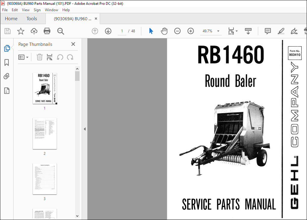
Gehl RB 1460 Round Baler Service Parts Manual(903410) – PDF DOWNLOAD
Gehl RB 1460 Round Baler Service Parts Manual(903410) – PDF DOWNLOAD
FILE DETAILS:
Gehl RB 1460 Round Baler Service Parts Manual(903410) – PDF DOWNLOAD
Language : English
Pages : 48
Downloadable : Yes
File Type : PDF
Size: 3.33 MB
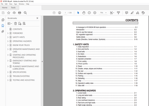
TABLE OF CONTENTS:
Gehl RB 1460 Round Baler Service Parts Manual(903410) – PDF DOWNLOAD
lntroduction Inside Front Cover
Table of Contents l
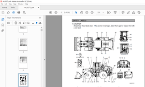
Decai Locations 2-3
Frame, Fenders & Twinebox 4-5
Drawbar, Axles & Ramps 6-7
lmplement Drive Line Shields & Covers 8
Pickup Lift & Overfill Clutch 9
Pickup 10-1 I
Bale Starter & Sera per I 2
Crossframe, Twine Tubes & Cutoff I 3
Spracket & Roller Part Number Guide 14
Shuttle & Bale Size lndicator I 5
Roller Drives 16-17
Upper Belts, Rollers & Related Components 18-19
Lower Rollers 20
Gate Hydraulics 21
Rear Gate 22-23
Total Density Contrai 24-25
Universal Drives 26-27
Transmission 28
H itchjacks 29
Options & Accessories 30-39
Electric Twine Wrapping Kit 30-31
Contrai Box & Wiring Diagram 30
Electric Actuators 3 I
Auto-Electric Twine Wrapping System 32-34
Wiring Diagram 33
Auto-Electric Actuator 33
Horn & lndicator Contrai Box 34
Flow Contrai Valve 34
Audible Bale Size Indicator Kit 35
Center Drive Roller Scraper Kit 35
Crowder Wheel Kit 36-37
1000 RPM Conversion Kit 37
6″ Upper Belt Dutchman 37
Re-lacing Kit 38
Packing Roller Sera per Kit 38
Lacing Kit 38
Packing Rol ler Lagging Kit 38
Bale Counter Kit 39
Dual Hydraulics Kit 39
Hydraulic Twine Wrapping Kit 39
Numerical lndex 40-43
Standard Hardware Torque Specifications Inside Back Cover
Attaching Hardware Table Inside Back Cover
DESCRIPTION:
Gehl RB 1460 Round Baler Service Parts Manual(903410) – PDF DOWNLOAD
Mr. Dealer:
- When ordering service parts, specify the correct part number, full description, quantity required, the unit model number and serial number. Numbers for this unit are on a decai located under the Top Channel, near the Center Column of the Left Frame Assembly.
- “Right” and “Left” are determined from a position standing at rear of the unit facing the direction of travei. From this position, the Universal Drive and Transmission are on the left side. GEHL Company reserves the right to make changes or improvements in the design or construction of any part of the unit without incurring the obligation to instai! such changes on any unit previously delivered
- Common attaching hardware, such as nuts, cap screws, etc. is listed in the parts list but NOT illustrated, except where a particular routing or special fastening arrangement MUST be maintained. ‘
- The hardware listed is for mounting purposes and is NOT included when the partis ordered for replacement. Refer to the abbreviations table for the various fastener descriptions
- For the part number of common hardware, refer to the Attaching Hardware Table located on the lnside Back Cover. Standard hardware torque values are also provided on the sarne page. U nless otherwise specified, ali Cap Screws or Bolts are Grade 5, cadmium or zinc plated; Hexagon Nuts for Grade 5 Cap Screws or Bolts are Grade B; Hexagon Nuts for other Cap Screws or Bolts are Grade A.
IMAGES PREVIEW OF THE MANUAL:
More products