$23
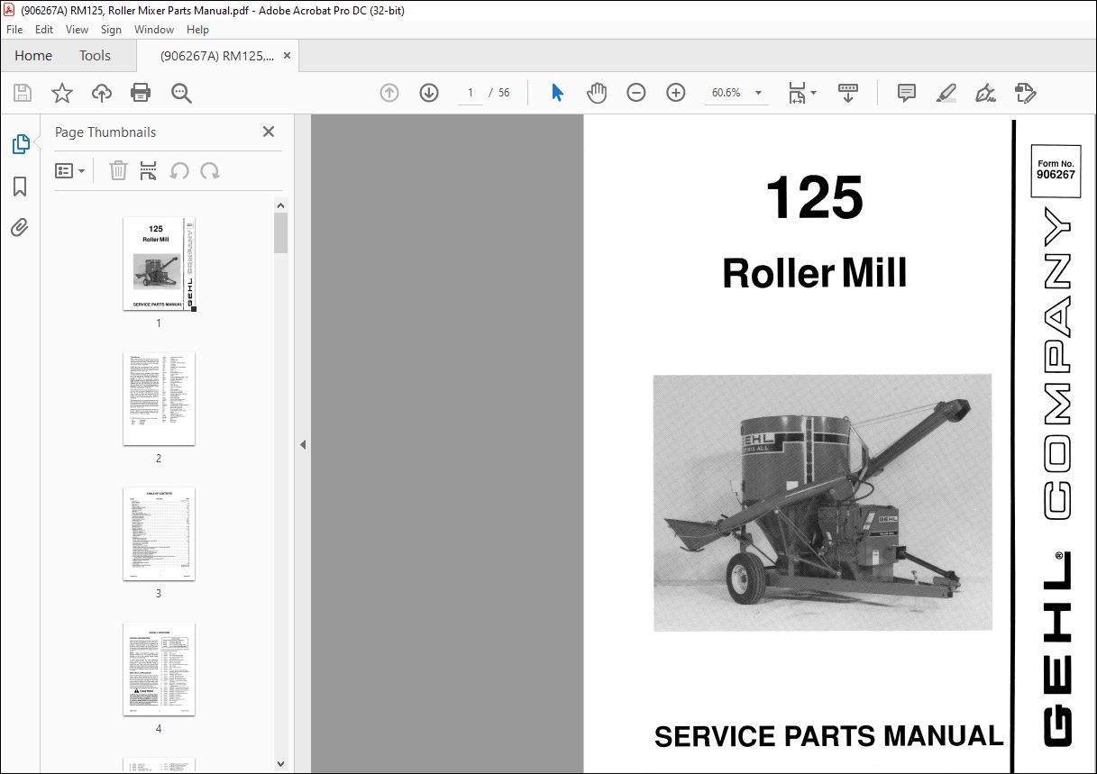
Gehl Roller Mill 125 Service Parts Manual(906267A) – PDF DOWNLOAD
Gehl Roller Mill 125 Service Parts Manual(906267A) – PDF DOWNLOAD
FILE DETAILS:
Gehl Roller Mill 125 Service Parts Manual(906267A) – PDF DOWNLOAD
Language : English
Pages : 56
Downloadable : Yes
File Type : PDF
Size: 6.92MB
IMAGES PREVIEW OF THE MANUAL:
DESCRIPTION:
Gehl Roller Mill 125 Service Parts Manual(906267A) – PDF DOWNLOAD
Introduction:
- When ordering service parts, specify the correct part number, full description, quantity required, and the unit model and serial numbers. The Roller Mill model and serial numbers are located on the Frame member in the rear at the base of the Tank.
- “Right” and “Left” are determined from a position standing behind the Roller Mill. From this position, the Concentrate Hopper is on the “left” side and the Feeder Attachment is on the “right” side. GEHL® Company reserves the right to make changes or improvements in the design or construction of any part of the unit without incurring the obligation to install such changes on any previously delivered units.
- Grease fittings and common attaching hardware, such as Cotter Pins, Set Screws, Woodruff Keys, Screws, Nuts, etc., are included in the parts lists, indented below the part it is (they are) associated with, but usually NOT illustrated, except where a particular routing or special fastening arrangement MUST be maintained.
- The hardware listed is for mounting information and is NOT included with the replacement part. Refer to the following abbreviations table for fastener descriptions. In the Parts List, if a number precedes the abbreviation, the number represents either quantity required (if other than one per item) or size
- Unless otherwise specified, all Cap Screws or Bolts are Grade S, cadmium or zinc plated; Hexagon Nuts for Grade S Screws or Bolts are Grade B; Hexagon Nuts for other Screws or Bolts are Grade A.
TABLE OF CONTENTS:
Gehl Roller Mill 125 Service Parts Manual(906267A) – PDF DOWNLOAD
Introduction Inside Front Cover
Table of Contents 1
Decal Locations 2-5
Basic Unit 6-7
Hopper Assembly 8-9
Chain Drive Shield Assembly 10-11
Hopper Lid Assembly 12-13
Auger Base Assembly 14
Chain Drive 15
Intake Auger Assembly 16-17
Loading Auger Hydraulics Drive 18
Loading Auger Support & Lift Mechanism 19
Transmission Components 20
Frame Axles & Hitchjack 21
Tank & Discharge Conveyor 22-23
Unloading Conveyor 24-25
Conveyor Winch 26-27
Conveyor & Mixer Drive 28-29
Concentrate Hopper 30
Telescoping PTO Drive 31
Hydraulics System 32-33
Hitchjack Components 34
Hydraulic Components 35-36
048968 Flow Control Valve 35
064675 Flow Regulator 35
065024 Gresen Selector Valve 35
064674 Cross Selector Valve 35
Charlynn Motors 36
Accessories 37-46
081198 Agitator Extension Kit 37
803320 10 000 lb Safety Chain 37
Electric Remote Unloading Conveyor Control 803423 38-39
Auxiliary Remote Control 802588 40
Winch Reduction Drive Kit 803421 40
Control Box 074578 41
ConveyorWormControl074588 41
Folding Unloading Conveyor 4-Ft Extension 803419 or 7-1/2 Ft Extension 803422 42
Conveyor Extension 1-Ft 802476 or 3-Ft 850252 43
Conveyor Extension Pivot 074799 43
801579 Audible Alarm for Model 1000 Microprocessor 44
801580 Visual Alarm for Model 1000 Microprocessor 44
804777 Audible Alarm for Model 10 Indicator 44
804778 Visual Alarm for Model 10 Indicator 44
Model 5 Scales Factor Installed 804759 or Field Installed 804761 or Model 10 Scales Factory
Installed 804760 or Field Installed 804762 45
Model 1000 Scale Factory Installed 802776 or Field Installed 802777 46
803839 Scale Battery Mounting Kit 47
801601 Fender Set 47
801666 Double Bagger Attachment 47
Numerical Index 48-52
Standard Hardware Torque Specifications Inside Back Cover
Attaching Hardware Table Inside Back Cover
More products