$28
GEHL RS5-34 Telescopic Loader Parts Manual(913228) – PDF DOWNLOAD
GEHL RS5-34 Telescopic Loader Parts Manual(913228) – PDF DOWNLOAD
IMAGES PREVIEW OF THE MANUAL:
DESCRIPTION:
GEHL RS5-34 Telescopic Loader Parts Manual(913228) – PDF DOWNLOAD
- The table of contents pages show the page location of various component groups on the machine. When ordering service parts, specify the correct part number, full description, quantity required, and the unit model and serial number. Model and serial numbers for this unit are stamped on a plate located inside the operator’s station. The serial number is also stamped on the top front frame. The following reference shows the breakdown of the serial number:
- “Right” and “left” are determined from a position sitting on the seat and facing forward. Gehl Company reserves the right to make changes or improvements in the design or construction of any part of the unit without incurring the obligation to install such changes on any unit previously delivered.
- Grease fittings and common attaching hardware, such as cotter pins, set screws, woodruff keys, screws, nuts, etc., are included in the parts list, indented below the part it is (they are) associated with, but may NOT be illustrated, except where a particular routing or special fastening arrangement MUST be maintained. The hardware listed is for mounting purposes and is NOT included when the part is ordered for replacement. Part numbers for standard hardware are listed indented under the component being fastened.
- A complete listing of part numbers for attaching washers/nuts used on this machine is included in the table on the facing page. Refer to the abbreviations list on the facing page for descriptions. Standard attaching hardware torque values are provided on the inside back cover. Unless otherwise specified, all cap screws are Grade 5, cadmium or zinc plated; hexagon nuts for Grade 5 cap screws or bolts are Grade 5.
TABLE OF CONTENTS:
GEHL RS5-34 Telescopic Loader Parts Manual(913228) – PDF DOWNLOAD
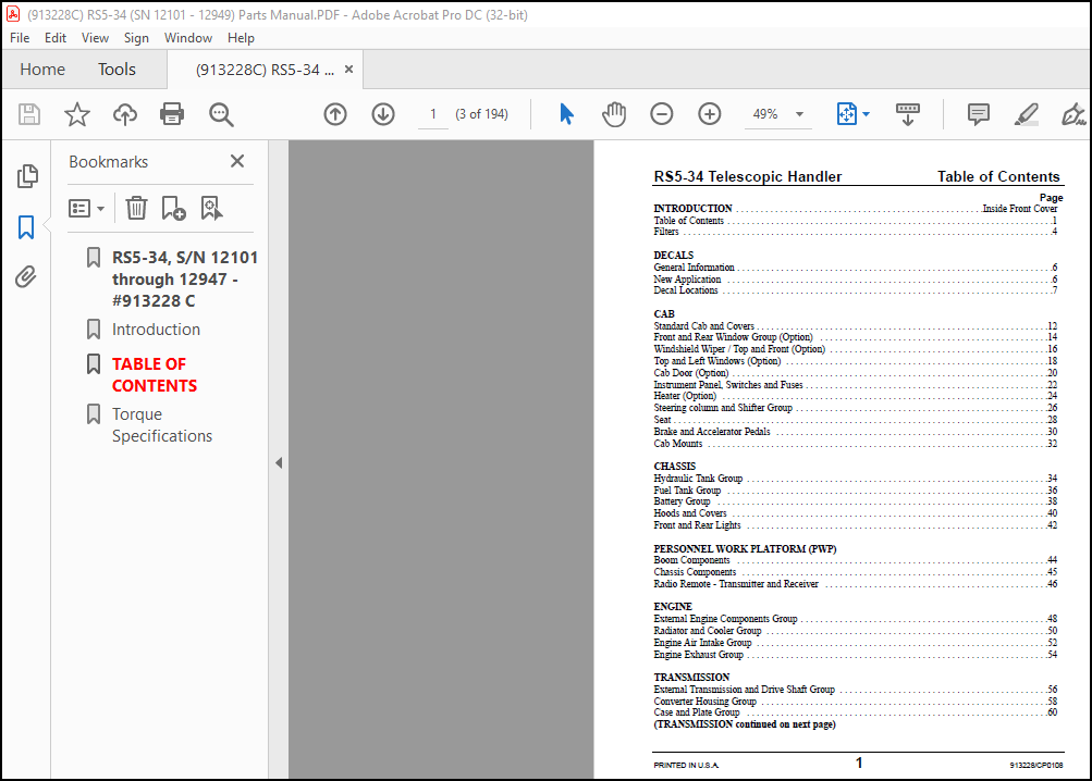
INTRODUCTION Inside Front Cover
Table of Contents 1
Filters 4
DECALS
General Information 6
New Application 6
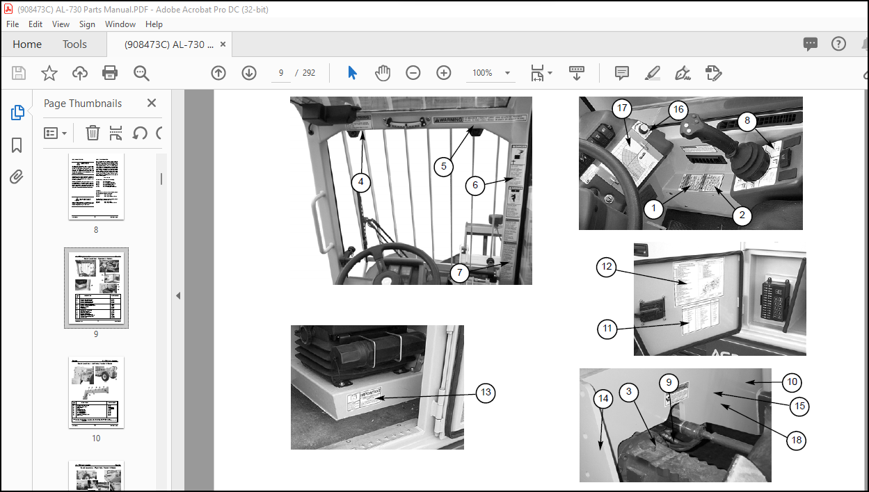
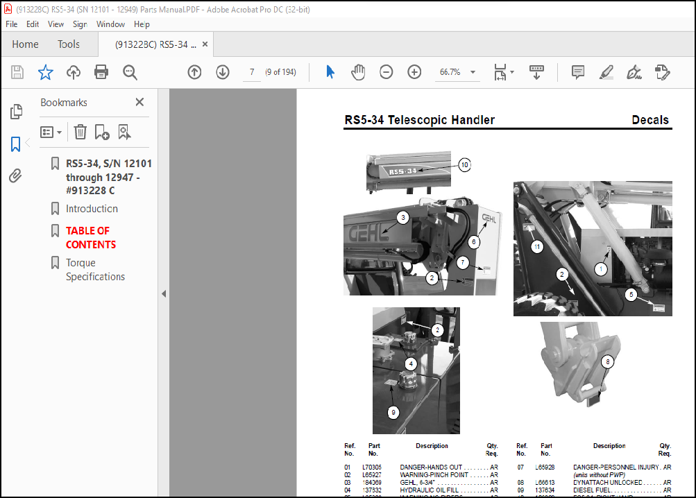
Decal Locations 7
CAB
Standard Cab and Covers 12
Front and Rear Window Group (Option) 14
Windshield Wiper / Top and Front (Option) 16
Top and Left Windows (Option) 18
Cab Door (Option) 20
Instrument Panel, Switches and Fuses 22
Heater (Option) 24
Steering column and Shifter Group 26
Seat 28
Brake and Accelerator Pedals 30
Cab Mounts 32
CHASSIS
Hydraulic Tank Group 34
Fuel Tank Group 36
Battery Group 38
Hoods and Covers 40
Front and Rear Lights 42
PERSONNEL WORK PLATFORM (PWP)
Boom Components 44
Chassis Components 45
Radio Remote – Transmitter and Receiver 46
ENGINE
External Engine Components Group 48
Radiator and Cooler Group 50
Engine Air Intake Group 52
Engine Exhaust Group 54
TRANSMISSION
External Transmission and Drive Shaft Group 56
Converter Housing Group 58
Case and Plate Group 60
(TRANSMISSION Continued)
Torque Converter Group 62
Gear Group 64
Pump Drive Group 66
Charge Pump Group 67
Reverse Idler Group 68
Forward and Reverse Group 70
Third Shaft Group 72
First and Second Shaft Group 74
Output Shaft Group 76
Control Group 78
Drive Plate Group 80
Modulation Valve Group 81
AXLES
External Components Group 82
Steering Cylinder and Tie Rods (Front Axle) 84
Steering Cylinder and Tie Rods (Rear Axle) 85
Differential Housing Group (Front Axle) 86
Differential Housing Group (Rear Axle) 87
Brake Group (Front Axle) 88
Brake Group (Rear Axle) 89
AXLE, FRONT
Outer End Group 90
Differential Group 92
AXLE, REAR
Outer End Group 94
Differential Group 96
BOOM
Outer Boom Section 98
Intermediate Boom Section 100
Inner Boom Section 102
Dynattach ® Assembly 104
HYDRAULIC SYSTEMS
Hydraulic Pump and Flow Divider 106
Steer Motor and Steer Select Valve 108
Brake Valve Group 110
Brake and Steering Lines Group 112
Main Valve Group 114
Main Valve / Hydraulic Controls (joysticks) 116
HYDRAULIC SYSTEMS continued)
Main Valve / Radio Remote Option 118
Hydraulic Controls – Standard 120
Hydraulic Controls – Auxiliary Hydraulic Option 122
Hydraulic Controls – PWP Only 124
Hydraulic Controls – PWP and Auxiliary Hydraulic Option 126
Hydraulic Controls – Radio Remote Option 128
Hydraulic Controls – Radio Remote Option w/PWP 130
Frame Level Group 132
Lift Cylinder Group 134
Tilt / Slave Cylinder Group 136
Boom Extend Cylinder Group 138
Auxilary Hydraulics Group 140
HYDRAULIC COMPONENTS
Hydraulic Pump 142
Flow Divider 143
Main Valve 144
PWP Valve 146
Steer Valve 147
Steer Motor 148
Brake Valve 149
Radio Remote Option Manifold 150
Controller – Tilt / Frame Level 152
Controller – Lift / Extend 154
Controller – Auxiliary Hydraulics Option 156
Frame Level Cylinder 158
Lift Cylinder 160
Slave Cylinder 162
Tilt Cylinder 164
Boom Extend Cylinder 166
Fork Shift Carriage Cylinder 168
Rotate Carriage Cylinder 169
ATTACHMENTS
Carriage Forks 170
Standard Carriage Attachment Group 172
Fork Shift Carriage Attachment Group 174
Rotate Carriage Attachment Group 176
Boom Attachment Group 178
180O Swing Platform 180
Bucket Attachment Group 182
NUMERICAL INDEX
Numerical Index List 184
More products