$28
GEHL RS6-34 Telescopic Handler Parts Manual(50960084) – PDF DOWNLOAD
GEHL RS6-34 Telescopic Handler Parts Manual(50960084) – PDF DOWNLOAD
IMAGES PREVIEW OF THE MANUAL:
DESCRIPTION:
GEHL RS6-34 Telescopic Handler Parts Manual(50960084) – PDF DOWNLOAD
Introduction
- When ordering service parts, specify the correct part number, full description, quantity required, the machine model number, and serial number. For your safety, and continued proper operation, use only genuine Manitou service parts.
- “Right” and “left” are determined from a position sitting on the seat inside the cab and facing forward. Gehl Company reserves the right to make changes or improvements in the design or construction of any part of the machine without incurring the obligation to install such changes on previously delivered machines.
- This parts manual identifies both standard and optional features for this model. Depending on the features of your machine, some of the items identified in the parts lists may, or may not, be included with your machine
Serial number breaks are indicated as follows:
• (SN 999 and before) – indicates serial numbers
up to and including 999.
• (SN 1000 – 2000) – indicates serial numbers from
1000 to 2000.
• (SN 999 and up) – indicates serial numbers
including 999 and after.
NOTE: When ordering parts, be sure to identify the last five
digits of the machine’s serial number (Unit Number).
TABLE OF CONTENTS:
GEHL RS6-34 Telescopic Handler Parts Manual(50960084) – PDF DOWNLOAD
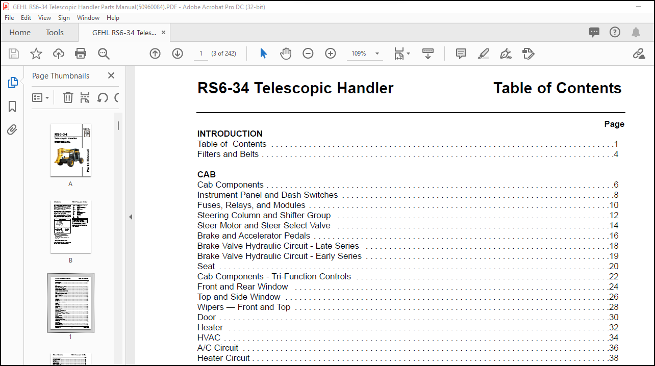
INTRODUCTION
Table of Contents 1
Filters and Belts 4
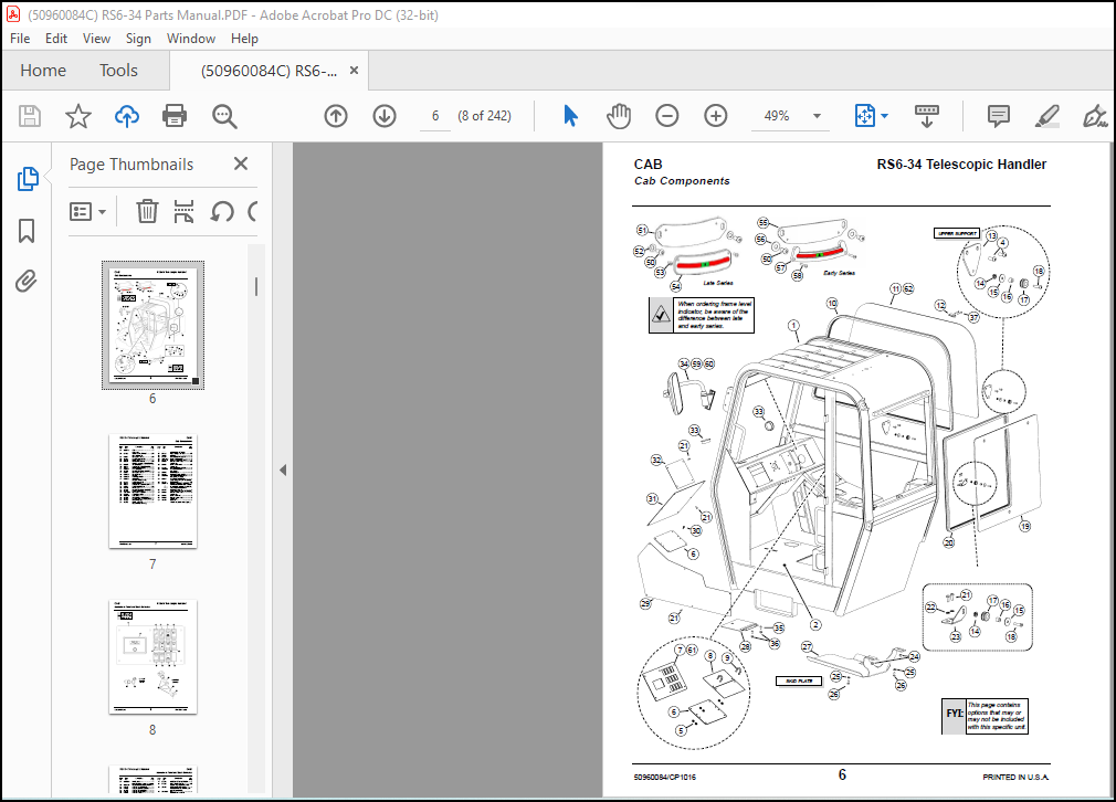
CAB
Cab Components 6
Instrument Panel and Dash Switches 8
Fuses, Relays, and Modules 10
Steering Column and Shifter Group 12
Steer Motor and Steer Select Valve 14
Brake and Accelerator Pedals 16
Brake Valve Hydraulic Circuit – Late Series 18
Brake Valve Hydraulic Circuit – Early Series 19
Seat 20
Cab Components – Tri-Function Controls 22
Front and Rear Window 24
Top and Side Window 26
Wipers — Front and Top 28
Door 30
Heater 32
HVAC 34
A/C Circuit 36
Heater Circuit 38
A/C Condenser 40
Cab Mounts 42
Front Work Lights and Strobe Light 43
CHASSIS
Hoods – Front 44
Hoods – Center 46
Hoods – Rear 48
Hydraulic Tank 50
Fuel Tank 52
Battery Group and ECU 54
Frame Level Circuit 56
PERSONNEL WORK PLATFORM
Boom Components – Standard 58
Level Sensor, Module, Chains, and Manifold 59
PWP Radio Remote – Transmitter and Receiver 60
ENGINE
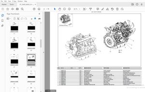
External Components 62
Block Heater 64
A/C Compressor Group 66
Fuel Circuit 68
Radiator and Cooler Group 70
Radiator and Cooler Components 72
Air Intake Group 74
Exhaust Group 76
Page
TRANSMISSION
External Components 78
Drive (Flex) Plate Group 80
Converter Housing Group 81
(Transmission continued)
Case and Plate Group 82
Torque Converter Group 84
Gear Group 86
Drive Pump Group 88
Charge Pump Group 89
Output Shaft Group 90
Reverse Idler Group 91
Forward and Reverse Group 92
Third Shaft Group 94
First and Second Shaft Group 96
Modulation Valve Group 98
Control Group 99
AXLE
External Components 100
Brake and Steering Circuit – Front Axle 102
Brake and Steering Circuit – Rear Axle 104
Front Axle – Steer Cylinder and Tie Rods Group 106
Rear Axle – Steer Cylinder and Tie Rods Group 107
Front and Rear Axle – Differential Housing Group 108
Brake Group – Front Axle 110
Brake Group – Rear Axle 112
Outer End Group – Front Axle 114
Differential Group – Front Axle 116
Outer End Group – Rear Axle 118
Differential Group – Rear Axle 120
BOOM
Outer Boom 122
Intermediate Boom 124
Inner Boom 126
Attachment Bracket Assembly 128
BOOM HYDRAULICS
Lift Circuit 130
Tilt / Slave Circuit 132
Boom Extend Circuit 134
Auxiliary Hydraulics Circuit 136
HYDRAULICS
Hydraulic Pump Group (SN 022971 and up; excluding 022972) 138
Hydraulic Pump Group (SN 022970 and before; including 022972) 140
Hydraulic Control Valve and Hoses 142
Dual Controls Circuit 144
Tri-Function Control – Standard Hydraulics Circuit 146
Tri-Function Control with Auxiliary Hydraulics Circuit 148
Radio Remote (Option) Circuit 150
Dual Controls – Standard 152
Dual Controls with Auxiliary Hydraulics 154
Dual Controls with PWP 156
Dual Controls with PWP and Auxiliary Hydraulics 158
Dual Controls with Radio Remote 160
Dual Controls with Radio Remote and Auxiliary Hydraulics 162
(Hydraulics continued)
Tri-Function Control with PWP 164
Tri-Function Control with PWP and Auxiliary Hydraulics 166
Tri-Function Control with Radio Remote 168
Tri-Function Control with Radio Remote and Auxiliary Hydraulics 170
HYDRAULIC COMPONENTS
Flow Divider Valve – Late Series 172
Flow Divider Valve – Early Series 173
Hydraulic Control Valve 174
PWP Valve 176
Steer Select Valve 178
Steer Motor and Brake Valve 180
Hydraulic Pump 181
Tilt Apply Manifold – Tri-Function- Late Series 182
Tilt Apply Manifold – Tri-Function- Early Series 183
Radio Remote Manifold 184
Controller – Tilt/Frame Level 186
Controller – Lift/Extend 188
Controller – Auxiliary Hydraulics (and Tri-Function Level) 190
Controller – Tri-Function 192
HYDRAULIC CYLINDER
Frame Level Cylinder 194
Lift Cylinder 196
Slave Cylinder 198
Tilt Cylinder 200
Boom-Extend Cylinder 202
Fork-Shift Cylinder – 48″ Carriage 204
Fork-Shift Cylinder – 50″ Carriage 205
Rotating-Carriage Cylinder 206
ATTACHMENTS
Carriage Forks 208
Standard Carriage 210
Fork-Shift Carriage – 48″ 212
Fork-Shift Carriage – 50″ 213
Rotating Carriage 214
Bucket, Truss Booms, Adapter Plate, and Winch 216
DECALS
General Information and Application Instructions 218
Paint 219
Front and Rear 220
Right Side 222
Left Side 223
Cab Interior 224
Jpystick Controls and Load Charts 226
NUMERIC INDEX 228
REFERENCE 238
More products