$32
Gehl RS6-34 Telescopic Handler Parts Manual(913317) – PDF DOWNLOAD
Gehl RS6-34 Telescopic Handler Parts Manual(913317) – PDF DOWNLOAD
IMAGES PREVIEW OF THE MANUAL:
DESCRIPTION:
Gehl RS6-34 Telescopic Handler Parts Manual(913317) – PDF DOWNLOAD
Introduction RS6-34 Telescopic Handler RS6-34 J D 00 00000 Model Year (E=13, F=14, etc.) Month Engine Unit Number When ordering service parts, specify the correct part number, full description, quantity required, the machine model number, and serial number. For your safety, and continued proper operation, use only genuine Manitou service parts. Right and left are determined from a position sitting on the seat inside the cab and facing forward. Gehl Company reserves the right to make changes or improvements in the design or construction of any part of the machine without incurring the obligation to install such changes on previously delivered machines. NOTE: This parts manual identifies both standard and optional features for this model. Depending on the features of your machine, some of the items identified in the parts lists may, or may not, be included with your machine
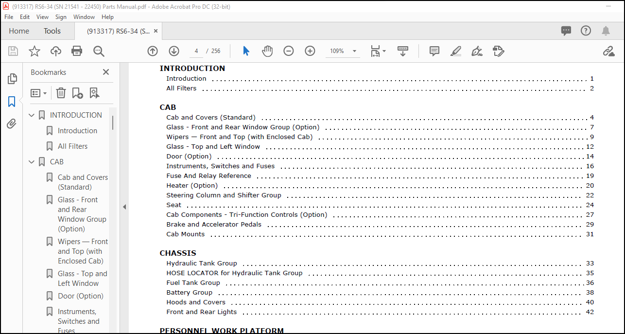
TABLE OF CONTENTS:
Gehl RS6-34 Telescopic Handler Parts Manual(913317) – PDF DOWNLOAD
INTRODUCTION………………………………………………………….. 7
Introduction………………………………………………………. 7
All Filters……………………………………………………….. 8
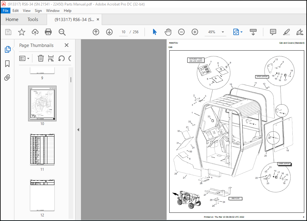
CAB………………………………………………………………….. 10
Cab and Covers (Standard)…………………………………………… 10
Glass – Front and Rear Window Group (Option)………………………….. 13
Wipers — Front and Top (with Enclosed Cab)……………………………. 15
Glass – Top and Left Window…………………………………………. 18
Door (Option)……………………………………………………… 20
Instruments, Switches and Fuses……………………………………… 22
Fuse And Relay Reference……………………………………………. 25
Heater (Option)……………………………………………………. 26
Steering Column and Shifter Group……………………………………. 28
Seat……………………………………………………………… 30
Cab Components – Tri-Function Controls (Option)……………………….. 33
Brake and Accelerator Pedals………………………………………… 35
Cab Mounts………………………………………………………… 37
CHASSIS………………………………………………………………. 39
Hydraulic Tank Group……………………………………………….. 39
HOSE LOCATOR for Hydraulic Tank Group………………………………… 41
Fuel Tank Group……………………………………………………. 42
Battery Group……………………………………………………… 44
Hoods and Covers…………………………………………………… 46
Front and Rear Lights………………………………………………. 48
PERSONNEL WORK PLATFORM………………………………………………… 51
Boom Components……………………………………………………. 51
Chassis Components…………………………………………………. 53
Radio Remote (Option) – Transmitter and Receiver – (Late Style)…………. 55
Radio Remote (Option) – Transmitter and Receiver – (Early Style)………… 57
ENGINE……………………………………………………………….. 59
External Components – Engine………………………………………… 59
Radiator and Cooler Group…………………………………………… 63
HOSE LOCATOR for Radiator and Cooler Group……………………………. 65
Air Intake Group…………………………………………………… 66
Exhaust Group……………………………………………………… 68
TRANSMISSION………………………………………………………….. 70
External Components – Transmission…………………………………… 70
HOSE LOCATOR for External Components…………………………………. 72
Converter Housing Group…………………………………………….. 73
Case and Plate Group……………………………………………….. 75
Torque Converter Group……………………………………………… 77
Gear Group………………………………………………………… 79
Drive Pump Group…………………………………………………… 81
Charge Pump Group………………………………………………….. 83
Reverse Idler Group………………………………………………… 85
Forward and Reverse Group…………………………………………… 87
Third Shaft Group………………………………………………….. 89
First and Second Shaft Group………………………………………… 91
Output Shaft Group…………………………………………………. 93
Control Group……………………………………………………… 95
Drive Plate Group………………………………………………….. 97
Modulation Valve Group……………………………………………… 99
AXLE………………………………………………………………….101
External Components – Axle…………………………………………..101
Front Axle – Steer Cylinder and Tie Rods Group…………………………103
Rear Axle – Steer Cylinder and Tie Rods Group………………………….105
Front Axle – Differential Housing Group……………………………….107
Rear Axle – Differential Housing Group………………………………..109
Front Axle – Brake Group…………………………………………….111
Rear Axle – Brake Group……………………………………………..113
Front Axle – Outer End Group…………………………………………115
Front Axle – Differential Group………………………………………118
Rear Axle – Outer End Group………………………………………….120
Rear Axle – Differential Group……………………………………….123
BOOM………………………………………………………………….125
Outer Boom Section………………………………………………….125
Intermediate Boom Section……………………………………………129
Inner Boom Section………………………………………………….131
Dynattach® Bracket Assembly………………………………………….133
HYDRAULIC SYSTEMS………………………………………………………135
Hydraulic Pump Group — (SN 21789 and up)………………………………135
Hydraulic Pump Group — (SN 21788 and before)…………………………..137
Steer Motor and Select Valve Group……………………………………139
HOSE LOCATOR for Steer Motor and Select Valve Group…………………….141
Brake Valve Group…………………………………………………..142
Brake and Steering Circuit…………………………………………..144
Main Hydraulic Valve and Hoses……………………………………….146
HOSE LOCATOR for Main Hydraulic Valve and Hoses………………………..148
Main Hydraulic Valve – Dual Controls (Standard)………………………..149
Main Valve with Tri-Function Control (Option) – Standard Hydraulics………151
Main Valve with Tri-Function Control (Option) with Auxiliary Hydraulics…..153
Main Valve with Radio Remote (Option)…………………………………155
Dual Controls – Standard…………………………………………….157
Dual Controls with only Auxiliary Hydraulics (Option)…………………..159
Dual Controls with only PWP (Option)………………………………….161
Dual Controls with PWP and Auxiliary Hydraulics (Option)………………..163
Dual Controls with Radio Remote (Option)………………………………165
Dual Controls with Radio Remote and Auxiliary Hydraulics (Option)………..167
Tri-Function Control (Option) with only PWP……………………………169
Tri-Function Control (Option) with PWP and Auxiliary Hydraulics………….171
Tri-Function Control (Option) with Radio Remote………………………..173
Tri-Function Control (Option) with Radio Remote and Auxiliary Hydraulics….175
Frame Level Circuit…………………………………………………177
Lift Circuit……………………………………………………….179
Tilt / Slave Circuit………………………………………………..181
Boom Extend Circuit…………………………………………………183
Auxiliary Hydraulics Circuit…………………………………………185
HYDRAULIC COMPONENTS……………………………………………………187
Hydraulic Pump……………………………………………………..187
Joystick Relief – Flow Divider……………………………………….189
Main Hydraulic Valve………………………………………………..191
PWP Valve………………………………………………………….193
Steer Select Valve………………………………………………….195
Steer Motor………………………………………………………..197
Brake Valve………………………………………………………..199
Pilot Apply Manifold – Tri-Function (Option)…………………………..201
Radio Remote Manifold — (Option)……………………………………..203
Controller – Tilt/Frame Level………………………………………..205
Controller – Lift/Extend…………………………………………….207
Controller – Tri-Function (Option)……………………………………209
Controller – Auxiliary Hydraulics (Option)…………………………….211
Frame Level Cylinder………………………………………………..213
Lift Cylinder………………………………………………………215
Slave Cylinder……………………………………………………..217
Tilt Cylinder………………………………………………………219
Boom-Extend Cylinder………………………………………………..221
Fork-Shift Cylinder…………………………………………………223
Rotating-Carriage Cylinder…………………………………………..225
ATTACHMENTS……………………………………………………………227
Carriage Forks……………………………………………………..227
Standard Carriage…………………………………………………..229
Fork-Shift Carriage…………………………………………………231
Rotating Carriage…………………………………………………..233
Truss Booms………………………………………………………..235
180º Swing Platform…………………………………………………237
Work Platform – Early Style………………………………………….239
Work Platform – Later Style………………………………………….241
Bucket…………………………………………………………….243
DECALS………………………………………………………………..245
General Information…………………………………………………245
Frame and Boom 1 of 2……………………………………………….246
Frame and Boom 2 of 2……………………………………………….248
Cab……………………………………………………………….250
PWP Equipped Units………………………………………………….252
REFERENCE……………………………………………………………..254
Torque Guides………………………………………………………254
More products