$26
GEHL Skid Loader 4510 Service Parts Manual(904059) – PDF DOWNLOAD
GEHL Skid Loader 4510 Service Parts Manual(904059) – PDF DOWNLOAD
IMAGES PREVIEW OF THE MANUAL:
DESCRIPTION:
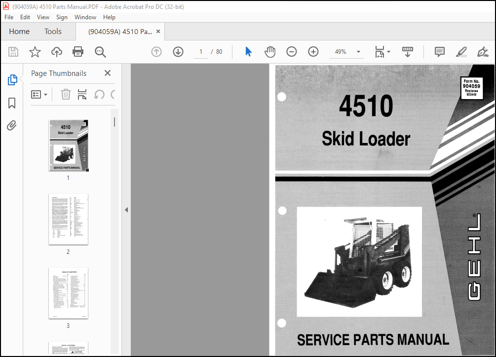
GEHL Skid Loader 4510 SERVICE Parts Manual(904059) – PDF DOWNLOAD
Introduction:
- When ordering service parts, specify the correct part number, full description, quantity required, and the unit model and serial numbers. Model and serial num bers for this unit are on a Decal located inside the Right Chassis Riser, between the Lift Arm and Lift Cylinder.
- “Right” and “Left” are determined from a position sitting on the Seat and facing forward. From this posi tion, the Propulsion Control T-bar is on the left and the Lift/Tilt Control T-bar is on the right. GEHL® Company reserves the right to make changes or improvements in the design or construction of any part of the unit without incurring the obligation to install such changes on any previously delivered units.
- On original Tire replacement, company policy prohibits the sale of replacement tires tor all original GEHL machinery. Replacement Wheel Sets are available and tire size information is called-out with the Wheel Sets to facilitate re placement tire selection. ALL REPLACEMENT TIRES MUST BE PURCHASED LOCALLY.
- Grease fittings and common attaching hardware, such as Cotter Pins, Set Screws, Woodruff Keys, Screws, Nuts, etc., are included in the parts lists, indented below the part it is (they are) associated with, but NOT illustrated, except where a particular routing or special fastening arrangement MUST be maintained. The hardware listed is for mounting information and is NOT included with the replacement part.
- Refer to the following abbreviations table for fastener descriptions. In the Parts List, if a number precedes the abbreviation, the number represents either quantity required (if other than one per item) or size. Unless otherwise specified, all Cap Screws or Bolts are Grade 5, cadmium or zinc plated; Hexagon Nuts for Grade 5 Screws or Bolts are Grade B; Hexagon Nuts for other Screws or Bolts are Grade A.
GENERAL INFORMATION
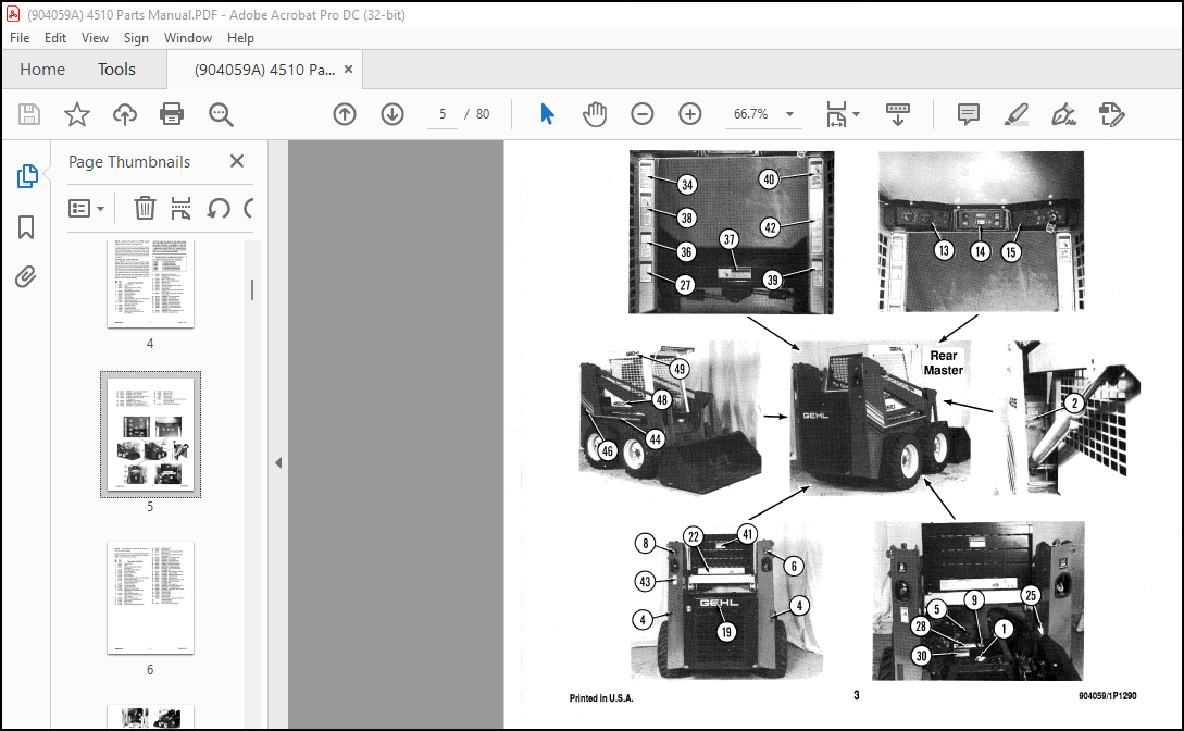
- Decal Locations inf onnation is provided to assist in the proper selection and application of new decals, in the event the original decal(s) become(s) damaged or the machine is repainted. Refer to the listing for the illustration reference number, part number, description and quantity of each decal provided in the Kit. Refer to the appropriate illustration(s) for replacement location(s).
- Refer to the SAFETY Chapter for the specific information provided on all of the various Safety Decals furnished in the Decal Kit(s). To ensure proper selection for correct replacement decal(s), compare all of the various closeup location photographs to your machine BEFORE starting to refinish the unit. Then, circle each pictured decal (applicable to your machine) while checking- off its part number in the listing. After you have verified all of the decal needed for replacement, set aside unneeded decals for disposal.
NEW DECAL APPLICATION
Surfaces MUST be free from dirt, dust, grease and other foreign material before applying the new decal. To apply a solidfo 皿ed decal, remove the smaller portion of the decal backing paper and apply this part of the exposed adhesive backing to the clean surface while maintaining proper position and alignment Slowly peel off the other portion of the bacldng paper while applying hand pressure to smooth-out the decal surface. The Decal Set Number for the SIA510 (Gasoline-powered) and SL4610 (Diesel-powered) Agricultural Skid Loaders is 096832. The Set includes the following:
TABLE OF CONTENTS:
GEHL Skid Steer 4510 Parts Manual(904059) – PDF DOWNLOAD
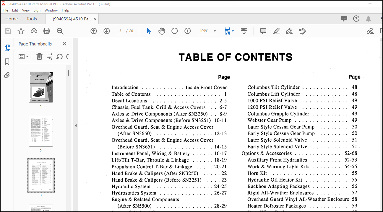
Introduction………… Inside Front Cover
Table of Contents……………… 1
Decal L ocations……………… 2-5
Chassis, Fuel Tank, Grill & Access Covers.. 6-7
Axles & Drive Components (After SN3250).. 8-9
Axles & Drive Components (Before SN3251) 10-11
Overhead Guard, Seat & Engine Access Cover
(After SN3650)……………. 12-13
Overhead Guard, Seat & Engine Access Cover
(Before SN3651).. ………… 14-15
Instrument Panel, Wiring & Battery…… 16-17
Lift/Tilt T-Bar, Throttle & Linkage…… 18-19
Propulsion Control T-Bar & Linkage….. 20-21
Hand Brake & Calipers (After SN3250)….. 22
Hand Brake & Calipers (Before SN3251)…. 23
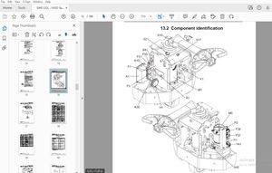
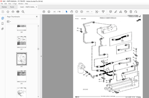
Hydraulic System……………. 24-25
Hydrostatics System…………… 26~27
Engine & Related Components
(After SNSSOO)……………. 28-29
Engine & Related Components
(Before SN5501)……. ……. 30-31
Air Cleaner, Alternator, Muffler & Radiator
(After SN5500)……………. 32-33
Air Cleaner, Alternator, Muffler &·Radiator
(Before SN5501).. …….. 34-35
Lift Arms & Hydrolock Mechanism
(After SN5300)……………. 36-37
Lift Arms & Hydrolock Mechanism
(Before SN5301)…………… 38-39
Lift & Tilt Cylinders & Hydraulics…….. 40
Pi;mps, Motors, Valves & Cylinders….. 41-51
Later Style Right Side Drive Pump……. 41
Early Style Right Side Drive Pump…… 42
Later Style Left Side Drive Pump……. 43
Early Style Left Side Drive Pump……. 44
Main Control Valve……………. 45
Auxiliary Control Valve…………. 46
Hydrostatic Drive Motor…………. 47
Page
Columbus Tilt Cylinder…………. 48
Columbus Lift Cylinder………… 48
1000 PSI Relief Valve…………. 49
1200 PSI Relief Valve…………. 49
Columbus Grapple Cylinder………. 49
Webster Gear Pump…………… 49
Later Style Cessna Gear Pump…….. 50
Early Style Cessna Gear Pump…….. 50
Later Style Solenoid Valve………. 51
Early Style Sol.enoid Valve………. 51
Options & Accessories…………. 52-68
Auxiliary Front Hydraulics…….. 52-53
Work & Warning Light Kits…….. 54-55
Horn Kit………………… 55
Hydraulic Oil Heater Kit………… 55
Backhoe Adapting Packages……….. 56
Rigid All-Weather Enclosures……… 57
Overhead Guard Vinyl All-Weather Enclosure 58
Heater Defroster Packages……….. 59
Door Wiper Packages………….. 60
Drawbar Kit… …………… 60
Spark Arrestor Muffler Kit……….. 60
Sound Deadening Packages………. 61
Back-up Alarm Packages………… 62
Enclosed Alternator Kit………… 62
Amber Warning Beacons………… 62
Pre-Cleaner Kit…………….. 64
Dual Element Air Cleaner Kit……… 65
Pallet Fork……………….. 65
Grapple Fork………………. 66
Manure Fork………………. 67
Attachment Hook Kit………….. 67
Dirt & Rock Teeth Kit…………. 67
Buckets…………………. 68
Numerical Index……………. 69-76
Hardware Torque Specifications Inside Back Cover
Attaching Hardware Table.. Inside Back Cover
More products