$36
Gehl Skid Loader 4610 Service Parts Manual(906014) – PDF DOWNLOAD
Gehl Skid Loader 4610 Service Parts Manual(906014) – PDF DOWNLOAD
DESCRIPTION:
Gehl Skid Loader 4610 Service Parts Manual(906014) – PDF DOWNLOAD
Introduction:
- When ordering service parts, specify the correct part number, full description, quantity required, and the unit model and serial numbers. Model and serial numbers for this unit are on a Decal located inside the Right Chassis Riser, between the Lift Arm and Lift Cylinder. “Right” and “Left” are determined from a position sitting on the Seat and facing forward. From this position, the Propulsion Control T-bar is on the left and the Lift/Tilt Control T-bar is on the right.
- GEHL® Company reserves the right to make changes or improvements in the design or construction of any part of the unit without incurring the obligation to install such changes on any previously delivered units. NOTE: On original Tire replacement, company policy prohibits the sale of replacement tires for all original GEHL machinery. Replacement Wheel Sets are available and tire size information is called-out with the Wheel Sets to facilitate replacement tire selection. ALL REPLACEMENT TIRES MUST BE PURCHASED LOCALLY.
- Grease fittings and common attaching hardware, such as Cotter Pins, Set Screws, Woodruff Keys, Screws, Nuts, etc., are included in the parts lists, indented below the part it is (they are) associated with, but NOT illustrated, except where a particular routing or special fastening arrangement MUST be maintained. The hardware listed is for mounting information and is NOT included with the replacement part.
- Refer to the following abbreviations table for fastener descriptions. In the Parts List, if a number precedes the abbreviation, the number represents either quantity required (if other than one per item) or size. Unless otherwise specified, all Cap Screws or Bolts are Grade 5, cadmium or zinc plated; Hexagon Nuts for Grade 5 Screws or Bolts are Grade B; Hexagon Nuts for other Screws or Bolts are Grade A.
GENERAL INFORMATION
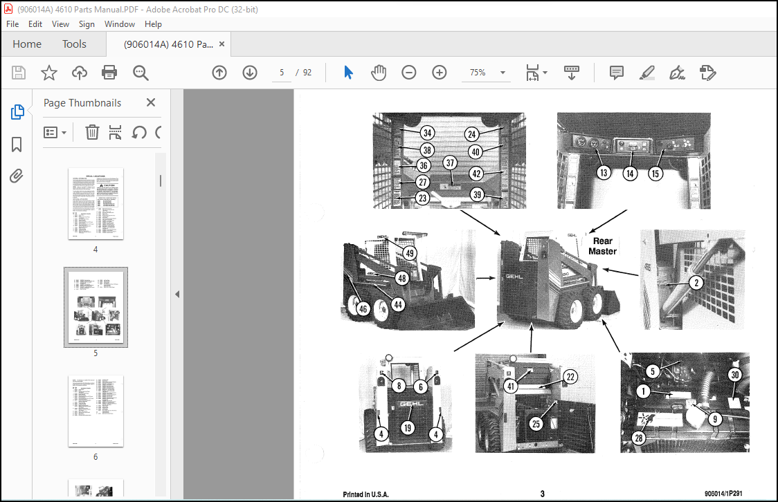
- Decal Locations information is provided to assist in the proper selection and application of new decals, in the event the original decals become damaged or the machine is repainted. Refer to the appropriate illustration to determine the reference number of the desired decal. Then, using the reference number, refer to the listing to determine the part number, description and quantity.
- To ensure proper selection of the correct replacement decals, carefully review all of the illustrations which pertain to your machine BEFORE starting to refinish the unit. Circle each decal reference number for the decals which will require replacement and then check it off in the parts list.
NEW DECAL APPLICATION
Surfaces MUST be free from dirt, dust, grease and other foreign material before applying the new Decal. To apply a solid-formed Decal, remove the smaller portion of the backing paper and apply this part of the exposed adhesive backing to the clean surface while maintaining proper position and alignment. Peel the other portion of the backing paper off slowly while applying hand pressure to smooth-out Decal surface.
TABLE OF CONTENTS:
Gehl Skid Loader 4610 Service Parts Manual(906014) – PDF DOWNLOAD
Introduction Inside Front Cover
Table of Contents 1
Decal Locations 2-5
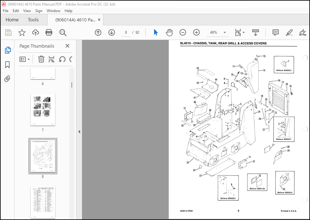
Chassis, Fuel Tank, Grill & Access Covers 6-7
Axles & Drive Components (After SN3600) 8-9
Axles & Drive Components (Before SN3601) 10-11
Overhead Guard, Seat & Engine Access Cover
(After SN4000) 12-13
Overhead Guard, Seat & Engine Access Cover
(Before SN4001) 14-15
Instrument Panel, Wiring & Battery
(After SN8500) 16-17
Instrument Panel, Wiring & Battery
(Before SN8501) 18-19
Lift/Tilt T-Bar, Throttle & Linkage 20-21
Propulsion Control T-Bar & Linkage
(After SN8500) 22-23
Propulsion Control T-Bar & Linkage
(Before SN8501) ,’ 24-25
Hand Brake & Calipers (After SN3600) 26
Hand Brake & Calipers (Before SN3601) 27
Hydraulic System (After SN8500) 28-29
Hydraulic System (Before SN8501) 30-31
Hydrostatics System (After SN8500) 32-33
Hydrostatics System (Before SN8501) 34-35
Engine & Related Components
(After SN8500) 36-37
Engine & Related Components
(Before SN8501) 38-39
Air Cleaner, Alternator, Muffler & Radiator
(After SN8500) 40-41
Air Cleaner, Alternator, Muffler & Radiator
(Before SN8501) 42-43
Lift Arms & Hydrolock Mechanism
(After SN6900) 44-45
Lift Arms & Hydrolock Mechanism
(Before SN6901) 46-4 7
Lift & Tilt Cylinders & Hydraulics 48
Pumps, Motors, Valves & Cylinders 49-61
Right Side Drive Pump (After SN8500) 49
Right Side Drive Pump (Before SN8501 &
After SNS216) 50
Right Side Drive Pump (Before SN5217) 51
Left Side Drive Pump (After SN8500) 52
Page
Left Side Drive Pump (Before SN8501 &
After SN5216) 53
Left Side Drive Pump (Before SN5217) 54
Main Control Valve 55
Auxiliary Control Valve 56
Hy drostatic Drive Motor 57
Columbus Tilt Cylinder 58
Columbus Lift Cylinder 58
1000 PSI Relief Valve 59
1200 PSI Relief Valve 59
Columbus Grapple Cylinder 59
Webster Gear Pump 59
Later Style Cessna Gear Pump 60
Early Style Cessna Gear Pump 60
Later Style Solenoid Valve 61
Early Style Solenoid Valve 61
Options & Accessories 62-78
Auxiliary Front Hydraulics 62-63
Work & Warning Light Kits 64-65
Horn Kit · 65
Hydraulic Oil Heater Kit 65
Backhoe Adapting Packages 66
Rigid All-Weather Enclosures 67
Overhead Guard Vinyl All-Weather Enclosure 68
Heater Defroster Packages 69
Door Wiper Packages 70
Drawbar Kit 70
Spark Arrestor Muffler Kit 70
Sound Deadening Packages 71
Back-up Alarm Packages 72
Enclosed Alternator Kit 72
Amber Warning Beacons 73
Pre-Cleaner Kit 74
Dual Element Air Cleaner Kit 75
Pallet Fork 75
Grapple Fork 76
Manure Fork 77
Attachment Hook Kit 77
Dirt & Rock Teeth Kit 77
Buckets 78
Numerical Index 79-87
Hardware Torque Specifications Inside Back Cover
Attaching Hardware Table Inside Back Cover
IMAGES PREVIEW OF THE MANUAL:
More products