$33
Gehl SL4640E SL5240E Deutz TD20009L4 Engine Skid Steer Loader Service Manual 917295 11.2008 – PDF
Gehl SL4640E SL5240E Deutz TD20009L4 Engine Skid Steer Loader Service Manual 917295 11.2008 – PDF DOWNLOAD
FILE DETAILS:
Gehl SL4640E SL5240E Deutz TD20009L4 Engine Skid Steer Loader Service Manual 917295 11.2008 – PDF DOWNLOAD
Language : English
Pages : 230
Downloadable : Yes
File Type : PDF
Size: 13.1 MB
IMAGES PREVIEW OF THE MANUAL:
DESCRIPTION:
Gehl SL4640E SL5240E Deutz TD20009L4 Engine Skid Steer Loader Service Manual 917295 11.2008 – PDF DOWNLOAD
INTRODUCTION:
- With correct maintenance and proper use, the Gehl 4640/5240E skid-steer loaders with a tier-III Deutz
TD2009L4 engine will give years of dependable service. This service manual addendum is intended to be
a guide in the assembly and disassembly, installation and removal, adjustment and testing,
troubleshooting and replacement of components that together make up the Gehl 4640/5240E skid-steer
loaders. - In many of the procedures found within, the installation steps are the exact opposite of the removal steps
and vice versa, and therefore, the opposite procedure is not written. Instead, a note to reverse the
procedure will be stated. This reduces redundancy and excessive pages in the manual. In cases though,
where the assembly and disassembly or removal and installation procedures differ and additional steps or
safety concerns are paramount, the entire reverse procedure will be written out to include the new
information. - The Table of Contents and Index can be used to make the procedure you need to find an easier process.
Many schematics, photographs, and line art drawings are used to help perform the necessary repairs,
tests, or adjustments that the skid-steer loader needs to keep it in good running condition. - If you have any additional questions, please contact your authorized Gehl dealer or call the Gehl Service
Department for assistance.
TABLE OF CONTENTS:
Gehl SL4640E SL5240E Deutz TD20009L4 Engine Skid Steer Loader Service Manual 917295 11.2008 – PDF DOWNLOAD
Specifications Page
SPECIFICATIONS 1
SPECIFICATIONS 3
Safety Page
General Information 5
Signal Words 5
Additional Safety Reminders 5
Mandatory Safety Shutdown Procedure 6
Lift Arm Support Device 7
Lift Arm Support Device Engagement 7
Lift Arm Support Device Disengagement 7
ROPS – Raising 8
ROPS – Lowering 9
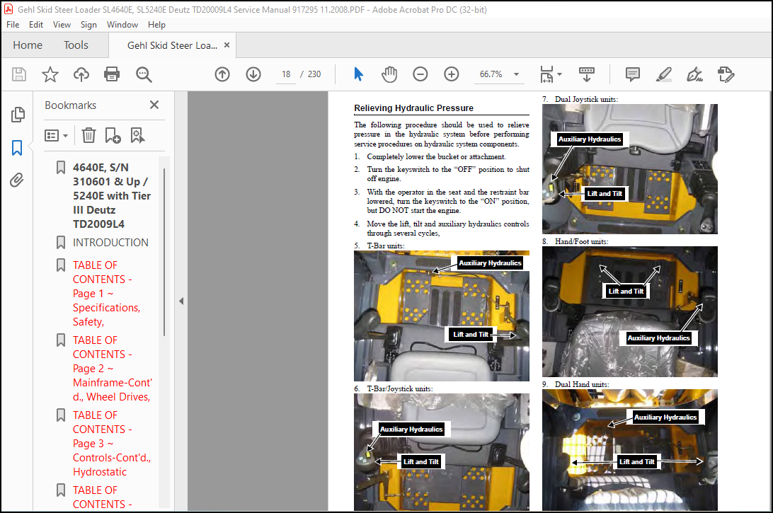
Relieving Hydraulic Pressure 10
Loader Raising Procedure 11
Loader Lowering Procedure 11
Lubrication System Page
General Information 13
Hydraulic Oil Reservoir 13
Crankcase Oil 14
Chaincases 15
Grease Fitting Locations 16
Cooling System Drain Procedure 16
Mainframe Page
Introduction 17
Mainframe (Chassis) Components 17
Rear Grille and Engine Cover Components 18
Engine Access Cover – Removal and Installation 19
Roll Over and Falling Object Protective Structure Components – ROPS/FOPS 20
ROPS Removal and Installation 21
Seat Removal and Installation 22
TABLE OF CONTENTS 4640E/5240E
2 PRINTED IN USA
Seat Slide Replacement 22
Air Duct Removal and Installation 23
Air Duct Louver Replacement 23
ROPS Rear Window Removal and Installation 23
Restraint Bar Removal and Installation 24
Restraint Bar Components 25
All-Tach® Components 25
Power-A-Tach® Components 26
Gehl All-Tach® or Power-A-Tach® Hitch Removal and Installation 27
Lift Arm Components 28
Lift Arm Removal and Installation 29
Lift Arm Bushing Replacement 32
Lift Arm Stop Installation and Adjustment 32
Control Cover Components 33
Floor Cover/Control Cover Removal and Installation 34
Crossmember Removal and Installation 36
Fuel Sensor Removal and Installation 39
Rear Grille Removal and Installation 40
Rear Grille Latch Removal and Installation 41
Wheel Drives Page
Introduction 43
Wheel Drive Components 43
Drive Chain Adjustment 44
Axle Housing Assembly Removal and Installation 45
Drive Chain Removal and Installation 46
Axle Assembly Components 47
Axle and Wheel Bearing Disassembly and Assembly 48
Controls Page
Introduction 51
Control Locations – Dual Joysticks 52
Control Locations – Dual Hand 52
Control Locations – T-Bar 53
Control Locations – Hand/Foot 53
Control Locations – T-Bar/Joystick 54
Wheel Drive Components – Dual Hand and Hand/Foot Controls 55
Wheel Drive Components – T-Bar and T-Bar/Joystick Controls 56
Wheel Drive Components – Dual Joystick Controls 57
Lift and Tilt Components – Dual Hand Controls 58
Lift and Tilt Components – T-Bar Controls 59
Lift and Tilt Components – Hand/Foot Controls 60
Lift and Tilt Components – T-Bar/Joystick and Dual Joystick Controls 61
Control Handle Removal and Installation – T-Bar, Dual Hand, Hand/Foot and the Left T-Bar/Joystick Control 62
Control Handle Assembly Removal and Installation – Dual Joystick Controls / Right T-Bar/Joystick Control 63
Electrical Auxiliary Grip Removal and Installation – Joystick Controls 65
4640E/5240E TABLE OF CONTENTS
PRINTED IN USA 3
Control Handle Position Adjustment – T-Bar, Dual Hand, Hand/Foot and the Left T-Bar/Joystick Control 67
Control Handle Tracking Adjustment, Wheel Drive Controls – T-Bar, Dual Hand, Hand/Foot, T-Bar/Joystick 68
Control Handle Tracking Adjustment, Wheel Drive Controls – Dual Joysticks 69
T-Bar Control Handle Assembly 70
Hand/Foot and Dual Hand Control Handle Assembly 72
Dual Joystick Assembly 74
Pivot Tube Removal and Installation 76
Neutral Centering Device Adjustment – Dual Hand, Hand/Foot, T-Bar and T-Bar/Joystick 77
Neutral Centering Adjustment – Dual Joysticks 78
Pump Control Arm Assembly Removal and Installation 79
Lift/Tilt Controls Removal and Installation 80
Lift/Tilt Control Adjustment 84
Auxiliary Hydraulics Controls – T-Bar and Dual Hand Controls 86
High-Flow Auxiliary Hydraulics Controls – T-Bar and Dual Hand Controls 87
Auxiliary Hydraulics Controls – Hand/Foot Controls 88
High-Flow Auxiliary Hydraulics Controls – Hand/Foot Controls 89
Standard and High-Flow Auxiliary Hydraulics Controls – Dual Joystick Controls 90
Auxiliary Hydraulics Cable Removal and Installation 91
Auxiliary Hydraulics Cable Adjustment 94
Hand Throttle Controls – T-Bar and Dual Hand Controls 96
Hand Throttle Controls – Hand/Foot Controls 97
Hand Throttle Controls – T-Bar/Joystick and Dual Joystick Controls 98
Hand Throttle, Foot Throttle Pedal and Throttle Cable Removal and Installation
– T-Bar, Dual Hand, T-Bar/Joystick and Dual Joystick 99
Hand Throttle Tension Adjustment 100
Hand Throttle and Throttle Cable Removal and Installation – Hand/Foot 101
Hand Throttle Adjustment – Hand/Foot 102
Foot Throttle Adjustment – T-Bar, Dual Hand, T-Bar/Joystick and Dual Joystick 103
Hydrostatic System Page
Introduction 105
Single-Speed Hydrostatic Components – T-Bar, Hand/Foot, Dual Hand and T-Bar/Joystick 105
Single-Speed Hydrostatic Components – Dual Joystick Controls 106
Two-Speed Hydrostatic Components – T-Bar, Hand/Foot, Dual Hand and T-Bar/Joystick 107
Two-Speed Hydrostatic Components – Dual Joystick Controls 108
Charge Pressure Test and Adjustment 109
Hydrostatic Pump Relief Valves 109
Hydrostatic Pump Removal / Installation 110
Hydrostatic Pump Drive Coupling Removal and Installation 111
Drive Motor Removal and Installation 112
Troubleshooting Guide 114
Hydrostatic/Hydraulic Schematic – Dual Joystick Controls 119
Hydrostatic/Hydraulic Schematic – Non-Dual Joystick Controls 120
TABLE OF CONTENTS 4640E/5240E
4 PRINTED IN USA
Hydraulic System Page
Introduction 121
Standard Auxiliary – T-bar, Dual Hand and Hand/Foot Controls 121
High-Flow Auxiliary – T-bar, Dual Hand and Hand/Foot Controls 122
Standard Auxiliary – T-bar/Joystick Controls 123
High-Flow Auxiliary – T-bar/Joystick Controls 124
Standard Auxiliary – Dual Joystick Controls 125
High-Flow Auxiliary – Dual Joystick Controls 126
Standard Lift Arm Hydraulics – 4640 Models 127
Standard Lift Arm Hydraulics – 5240 Models 128
High-Flow Lift Arm Hydraulics 129
Chassis Hydraulics 130
Pressure Tests, Control Valve and High-Flow 131
Tilt Cylinder Test 132
Self-Leveling Valve Test 133
Lift Cylinder Test 134
Solenoid Valve Test – Tilt, Lift, Brake and Two-Speed 135
Hydraulic Oil Filter Element Replacement 136
Tilt Cylinder Removal and Installation 137
Lift Cylinder Removal and Installation 138
Lift Cylinder Components 140
Tilt Cylinder Components 140
Lift/Tilt Cylinder Disassembly / Assembly 141
Gear Pump Removal and Installation 142
Self-Leveling Valve Removal and Installation 143
Self-Leveling Valve Adjustment 145
Safety Lock Valves – Removal/Installation 146
Lift and Tilt Solenoid Valve – Disassembly and Assembly 147
Control Valve Removal and Installation 148
Manifold Valve Removal and Installation 150
Control Valve Disassembly and Assembly 151
Main Relief Valve Removal and Installation 152
Auxiliary Hydraulics Spool Lock Solenoid Removal and Installation 153
Hydraglide™ Ride Control Hydraulics 154
Hydraglide™ Ride Control Accumulator Removal and Installation 155
Electrical System Page
Introduction 163
Description of Operation – Right and Left Instrument Panels 163
Electrical Chassis Components 167
Electrical Battery Disconnect Switch Components 168
Electrical Two-Speed Control Components 168
Electrical ROPS/FOPS Components 169
Master Fuse, Module and Relay Test and Operation 170
Master Fuse Test 170
Power Relay Test 170
ISO SPDT Interlock, Joystick, EGR, Fuel and Horn Relays Test 171
Starter and Glow Solenoid Test 172
Glow Control Module Test 172
4640E/5240E TABLE OF CONTENTS
PRINTED IN USA 5
Glow Control Module 173
Glow Control Module Time/Temp Cycle 173
Interlock Control Module Test 174
Interlock Control Module Truth Table 175
Two-Speed, Ride Control and Float Module Test 176
Two-Speed, Ride Control and Float Module Truth Table 177
Control Handle Actuation Buttons – Two-Speed and Ride Control and Float Module 178
Seat Switch Removal and Installation 179
Restraint Bar Components 180
Restraint Bar Switch Removal and Installation 181
Engine Disconnect Switch – Remote Battery Terminal Removal and Installation 182
Electrical Lights Components 183
Front and Rear Work Light Bulb Replacement 184
Dome Light Bulb Replacement 184
Electrically-controlled Standard Auxiliary Hydraulic Flow System Test and Operation 185
Electrically-controlled High-Flow Auxiliary Hydraulic Flow System Test and Operation 186
Lift and Tilt Solenoid Test and Operation 186
Traction Solenoid Test and Operation 187
Auxiliary Neutral Start Switch 187
2-Bank and 4-Bank Coil Function Colored Wire Connector Chart 188
Chassis – Electrical Schematic 189
ROPS/FOPS – Electrical Schematic 190
Engine – Electrical Schematic 191
Electrical Auxiliary Schematic 192
EGR Solenoid – Electrical Schematic 193
Heater Schematic 194
Engine Page
Introduction 195
Troubleshooting Guide 195
Engine Components 197
Air Cleaner and Exhaust Components 198
Radiator/Cooler Components 199
Remote Oil Filter Element Removal and Installation 200
Air Cleaner Assembly Removal and Installation 201
Air Filter Element Removal and Installation 202
Battery and Battery Tray Removal and Installation 203
Starter Removal and Installation 204
Exhaust Assembly Removal and Installation 205
Fan Belt Adjustment 205
Radiator/ Oil Cooler Removal and Installation 206
Fan Shroud and Radiator/Oil Cooler Mounting Brackets Removal and Installation 208
Fan Shroud Adjustment 209
Fan Removal and Installation 210
Engine Removal and Installation 211
Index 215
More products