$34
Gehl Telescopic Handler DL11 44 55 GEN3 DL12 40 55 GEN3 MTA 12055 Series 3 Service Manual 50960201
Gehl Telescopic Handler DL11 44 55 GEN3 DL12 40 55 GEN3 MTA 12055 Series 3 Service Manual 50960201 – PDF DOWNLOAD
IMAGES PREVIEW OF THE MANUAL:
DESCRIPTION:
Gehl Telescopic Handler DL11 44 55 GEN3 DL12 40 55 GEN3 MTA 12055 Series 3 Service Manual 50960201 – PDF DOWNLOAD
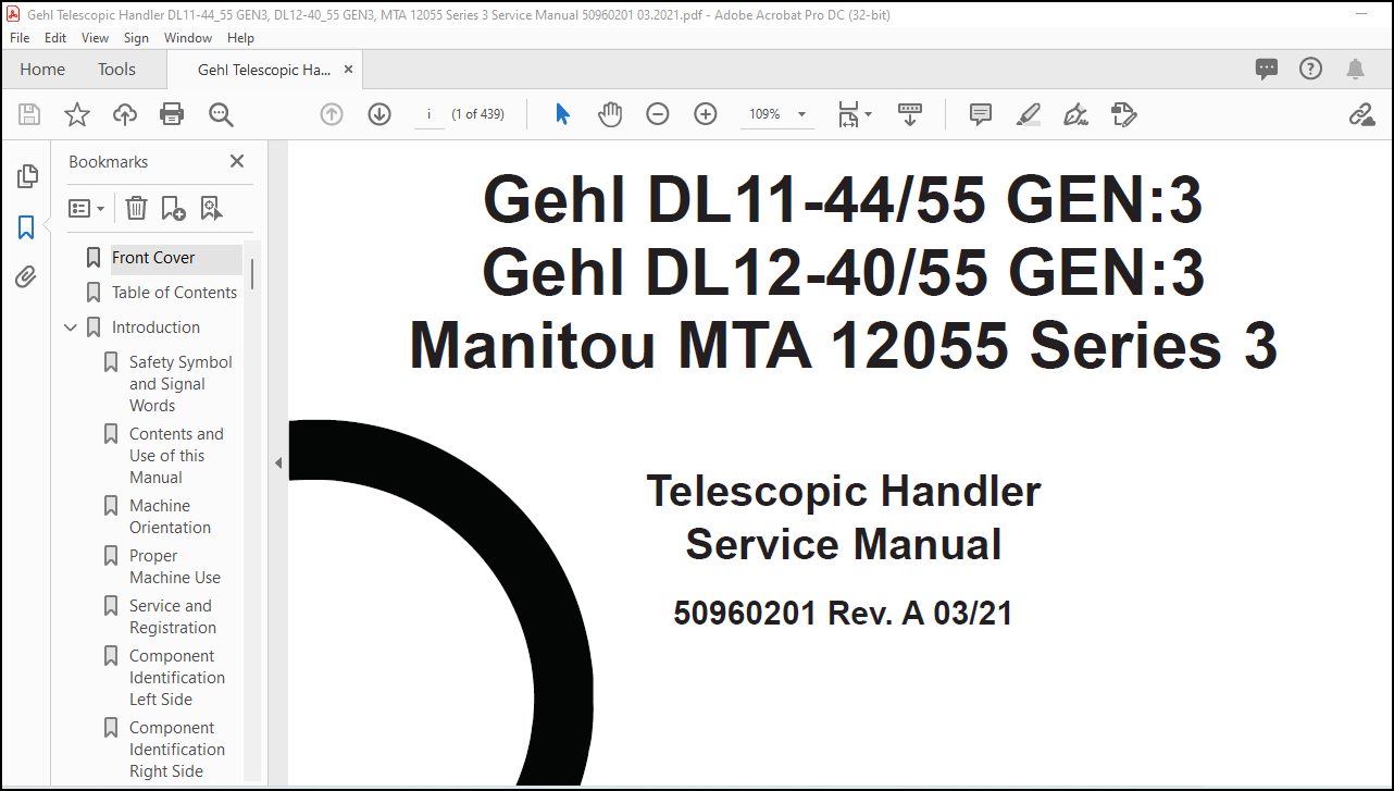
Gehl DL11-44/55 GEN:3
Gehl DL12-40/55 GEN:3
Manitou MTA 12055 Series 3
INTRODUCTION
- Safety Symbol and Signal Words This manual and decals on the machine warn of safety hazards and should be read and observed closely. Manitou Group, in cooperation with the Society of Automotive Engineers, has adopted this: This symbol is used throughout this operator’s manual and on the decals on the machine. It identifies potential safety hazards, which, if not properly avoided, could result in injury. When you see this symbol in this manual or on the machine, you are reminded to BE ALERT! Personal safety is involved!
- IMPORTANT: The word “IMPORTANT” indicates situations that can result in possible damage to the machine.
- It is the owner’s or employer’s responsibility to fully instruct each operator in the proper and safe operation and maintenance of the machine. A storage location is provided behind the operator’s seat for storing the operator’s manual. After using the manual, return it to the storage container.
- This manual is considered a permanent part of the machine and should be with the machine at all times. If the machine is resold, include this operator’s manual as part of the sale.
- Replace this manual promptly if it becomes damaged, lost or stolen. Some illustrations in this manual may show doors, guards and shields open or removed for illustrative purposes only.
- BE SURE all doors, guards and shields are in their proper operating positions BEFORE starting the engine to operate the machine. Because of ongoing product improvements, information included in this manual may not exactly match the machine. Manitou Group reserves the right to modify and improve products at any time without notice or obligation.
TABLE OF CONTENTS:
Gehl Telescopic Handler DL11 44 55 GEN3 DL12 40 55 GEN3 MTA 12055 Series 3 Service Manual 50960201 – PDF DOWNLOAD
Introduction. 1
Safety Symbol and Signal Words . 1
Contents and Use of this Manual. 1
Machine Orientation . 2
Proper Machine Use. 2
Service and Registration . 2
Component Identification Left Side. 6
Component Identification Right Side. 7
List of Attachments . 8
Using Attachments . 9
Manufacturer Information . 9
Indicator and Operation Symbols. 10
Safety. 12
Safety Symbol and Signal Words . 12
Mandatory Safety Shutdown Procedure. 13
Before Operation Safety Reminders. 14
Operation Safety Reminders. 15
Applications with Load-Handling Devices . 19
Suspended Load Safety Reminders . 24
Parking the Machine. 25
Electrical Energy . 25
Maintenance and Service Safety Practices. 26
Battery Hazards. 27
Fire Hazards . 28
Additional Safety Equipment . 29
Crystalline Silica Exposure. 29
Personnel Work Platform (PWP) System. 29
Wireless Remote Bettery Replacement. 31
Work Platform Design Requirements (Per ANSI/ITSDF B56.6 – 2016, Sec. 8.24). 31
Safety Decals . 33
New Decal Application. 33
Lubrication . 40
General Information. 40
Types of Lubricants and Capacities . 40
Lubrication Points. 41
Filter Table . 44
Maintenance . 46
Maintenance Schedule . 46
Maintenance Interval . 48
Grease Points . 48
Engine Maintenance. 48
Fuel System Maintenance. 55
Diesel Exhaust System (DEF) Maintenance. 58
Transmission Maintenance. 60
Axle Maintenance. 61
Transfer Case Oil . 62
Hydraulic System Maintenance . 63
Battery and Cable Maintenance . 68
HVAC/Air Conditioning Maintenance. 70
Check Instruments Operation. 71
Check General Machine Operation and Condition. 71
Check Personnel Work Platform (PWP) System (if used). 71
Storage . 72
PWP System Operational Troubleshooting. 74
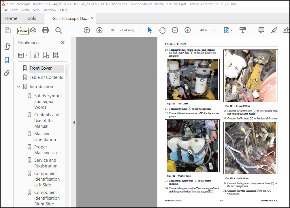
POWERTRAIN. 79
Engine. 79
Transmission. 124
Transfer Case Repair. 130
Cooling Package. 141
Rear Axle . 154
Front Axle. 162
HydraulicS. 173
Frame Leveling Cylinder . 173
Tilt Cylinder. 176
Hydraulic Cylinder Repair. 180
Stabilizer Cylinder . 188
Stabilizer Cylinder Repair. 191
Slave Cylinder. 202
Lift Cylinder. 205
Boom Extend Cylinder- Four Section Boom. 208
Boom Extend Cylinder-Three Section Boom. 211
Hydraulic Pump . 215
Hydraulic Control Valve-Main. 218
Hydraulic Testing and Adjustment Procedures. 221
Hydraulic System Testing. 223
Main Control Valve Pressure Relief Test and Adjustment. 243
Joystick Control and Park Brake Pressure Test . 245
Steering Circuit Pressure Test. 249
HYDRAULIC Schematics. 252
Hydraulic Schematic. 252
Intentionally Blank. 253
Electrical Schematics. 254
Electrical Schematic – (Continued on Next Page) . 254
Electrical Schematics – (Continued from Previous Page). 255
TELESCOPIC BOOM. 256
Overview 4-Section Boom. 256
Boom Assembly Removal and Installation (4-Section Boom). 260
1st Intermediate Boom Section Removal and Installation (4-Section Boom). 265
2nd Intermediate Boom Section Removal and Installation (4-Section Boom). 273
Inner Boom Section Removal and Installation (4-Section Boom). 287
Boom Hydraulic Hose and Tube Replacement (4-Section Boom). 294
Boom Pad Overview (4-Section Boom). 311
Boom Pad Replacement (4-Section Boom) . 315
1st Intermediate Boom. 319
2nd Intermediate Boom Rear Pad Replacement. 328
2nd Intermediate Boom Front Pad Replacement . 336
Inner Boom. 339
Overview Boom Chain and Rollers (4-Section Boom) . 348
Inner Boom Top Chain and Roller Replacement (4-Section Boom) . 350
Bottom Inner Boom Chain and Roller Replacement (4-Section Boom) . 360
2nd Intermediate Boom Chain and Roller Replacement (4-Section Boom). 367
Outer Boom Chain and Roller Replacement (4-Section Boom). 377
Boom Chain Adjustment (4-Section Boom). 382
Three Section Boom. 384
Leaf Chain Adjustment and Maintenance (3-Section Boom). 388
Inner Boom Removal and Installation (3-Section Boom) . 389
Extend Cylinder (3-Section Boom) . 396
Double Chain and Roller Bearing Replacement (3-Section Boom). 400
Single Chain and Roller Bearing Replacement (3-Section Boom). 405
Intermediate Boom Section Removal and Installation (3-Section Boom). 411
Boom Pad Replacement (3-Section Boom) . 417
SPECIFICATION. 422
Machine Configuations. 422
Lifting Performance . 422
Loader Performance. 423
General Dimensions. 424
Multi-Functional Display. 425
Steering System . 425
Braking System. 425
Electrical System . 426
Service Capacities (All Models). 426
Transmission Type (All Models) . 426
Axles (Front and Rear) (All Models). 426
Drive Train (All Models) . 427
Operator’s Station. 428
Torque Specifications. 432
More products