$35
Gehl Telescopic Handler RS4-14 H 57K ST5 S2 RS4-14 H TSS 57K ST5 S2 SERVICE MANUAL(647742) – PDF
Gehl Telescopic Handler RS4-14 H 57K ST5 S2 RS4-14 H TSS 57K ST5 S2 SERVICE MANUAL(647742) – PDF DOWNLOAD
IMAGES PREVIEW OF THE MANUAL:
 DESCRIPTION:
Gehl Telescopic Handler RS4-14 H 57K ST5 S2 RS4-14 H TSS 57K ST5 S2 SERVICE MANUAL(647742) – PDF DOWNLOAD
FOREWORD
This chapter deals with the general instructions and safety notice during servicing checks and work. The other instructions and warning texts are indicated in the chapters concerned. In order to reduce the risk of accidents, please:
• Follow the instructions in the operator’s manual and the truck servicing instructions. >
• This manual should be found in all trucks.
• Please follow the safety instructions.
• Use the appropriate tools for all work to be carried out.
• Use original Manitou spare parts.
If these instructions are not followed there is a risk of accidents occurring, the severity of which could go as far as causing death. A person who follows the safety instructions and a wellserviced machine make a safe, effective and profitable combination.
TABLE OF CONTENTS:
Gehl Telescopic Handler RS4-14 H 57K ST5 S2 RS4-14 H TSS 57K ST5 S2 SERVICE MANUAL(647742) – PDF DOWNLOAD
Legal disclaimer ……………………………………………………………………………………………. 3
List of Abbreviations ……………………………………………………………………………………….. 11
Intervention during the warranty period ……………………………………………………………………….. 13
Foreword …………………………………………………………………………………………………… 13
Servicing position ………………………………………………………………………………………….. 13
Explanation of symbols ………………………………………………………………………………………. 13
Servicing Rules …………………………………………………………………………………………….. 14
Supplier Documentation List (ST-5) ……………………………………………………………………………. 17
Characteristics and specifications ……………………………………………………………………………. 17
Technical datasheet RS 4-14 ………………………………………………………………………………. 17
Engine ……………………………………………………………………………………………… 17
Transmission ………………………………………………………………………………………… 18
Electrical system ……………………………………………………………………………………. 18
Noise and vibration ………………………………………………………………………………….. 18
Braking circuit ……………………………………………………………………………………… 19
Hydraulic system …………………………………………………………………………………….. 19
Hydraulic movements ………………………………………………………………………………….. 19
Specifications and weights ……………………………………………………………………………. 20
Technical datasheet RS 4-14 TSS …………………………………………………………………………… 20
Engine ……………………………………………………………………………………………… 20
Transmission ………………………………………………………………………………………… 21
Electrical system ……………………………………………………………………………………. 21
Noise and vibration ………………………………………………………………………………….. 22
Braking circuit ……………………………………………………………………………………… 22
Hydraulic system …………………………………………………………………………………….. 22
Hydraulic movements ………………………………………………………………………………….. 22
Specifications and weights ……………………………………………………………………………. 23
Dimensions RS4-14 H 57K ST5 S2 ……………………………………………………………………………. 24
Dimensions RS4-14 H TSS 57K ST5 S2 ………………………………………………………………………… 25
Location …………………………………………………………………………………………………… 27
Location of name and identification plate ………………………………………………………………….. 27
Control and adjustment ………………………………………………………………………………………. 28
Standard tightening torques ………………………………………………………………………………. 28
Metric – imperial unit conversion …………………………………………………………………………. 29
Characteristics and specifications ……………………………………………………………………………. 31
Third party documents list (ST5) ………………………………………………………………………….. 31
General characteristics (ST5) …………………………………………………………………………….. 31
Regeneration characteristics (ST5) ………………………………………………………………………… 31
Regeneration status levels ……………………………………………………………………………. 31
Decontamination prompt levels (degraded modes) ……………………………………………………………… 32
Decontamination prompt levels …………………………………………………………………………. 32
Flow diagrams and schematic diagrams ………………………………………………………………………….. 32
High pressure fuel system operation ……………………………………………………………………….. 32
Key ………………………………………………………………………………………………… 32
Lower cooling circuit bypass system ……………………………………………………………………….. 32
Key: ……………………………………………………………………………………………….. 33
Synoptic exhaust circuit …………………………………………………………………………………. 33
Key: ……………………………………………………………………………………………….. 33
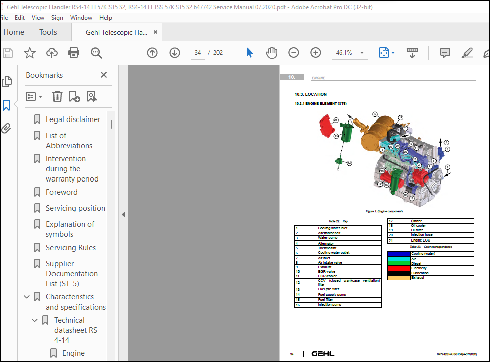
Location …………………………………………………………………………………………………… 34
Engine components (ST5) ………………………………………………………………………………….. 34
Engine components ……………………………………………………………………………………. 34
Key ………………………………………………………………………………………………… 34
Color correspondence …………………………………………………………………………………. 34
Control and adjustment ………………………………………………………………………………………. 35
Fan control …………………………………………………………………………………………….. 35
Location of ventilation control ……………………………………………………………………….. 35
Key: ……………………………………………………………………………………………….. 35
Key: ……………………………………………………………………………………………….. 35
Key: ……………………………………………………………………………………………….. 36
Fan speed values …………………………………………………………………………………….. 37
Fan speed measurements with electrovalves disconnected (maximum fan speed achieved according to engine speed): …. 37
Key: ……………………………………………………………………………………………….. 38
Engine silent block tightening torques …………………………………………………………………….. 39
Cooling system tightening torques …………………………………………………………………………. 40
Removal ……………………………………………………………………………………………………. 41
Preparation and Safety Instructions (Telehandler) …………………………………………………………… 41
Remove the side case …………………………………………………………………………………….. 41
Remove the engine cover (RS4-14…ST5) ………………………………………………………………………. 41
Remove the air filter cap support ……………………………………………………………………… 41
Remove the engine hood ……………………………………………………………………………….. 41
Remove the mudguard and the engine rear casing ……………………………………………………………… 41
Remove the mudguard ………………………………………………………………………………….. 42
Remove the engine rear casing …………………………………………………………………………. 42
Remove/Reinstall the Alternator Belt ………………………………………………………………………. 42
Replace the alternator belt …………………………………………………………………………… 42
Remove the alternator ……………………………………………………………………………………. 42
Remove the alternator ………………………………………………………………………………… 42
Remove the starter ………………………………………………………………………………………. 42
Remove the starter …………………………………………………………………………………… 43
Remove the air filter assembly ……………………………………………………………………………. 43
Remove the air intake hose ……………………………………………………………………………. 43
Remove the front mudguard …………………………………………………………………………….. 43
Remove the air filter ………………………………………………………………………………… 43
Remove the engine and the ventilation grille ……………………………………………………………….. 43
Disconnect the fan motor ……………………………………………………………………………… 44
Remove the propeller …………………………………………………………………………………. 44
Separate the motor from the grille …………………………………………………………………….. 44
Remove the radiator ……………………………………………………………………………………… 44
Disconnect the radiator ………………………………………………………………………………. 44
Remove the radiator ………………………………………………………………………………….. 45
Remove the ventilation control unit ……………………………………………………………………….. 45
Remove the fan control unit …………………………………………………………………………… 45
Remove the cooler support ………………………………………………………………………………… 45
Remove the cooler bracket …………………………………………………………………………….. 45
Remove the exhaust line (ST5) …………………………………………………………………………….. 45
Unscrew the exhaust pipe ……………………………………………………………………………… 45
Disconnect the DPF connectors …………………………………………………………………………. 46
Unscrew the muffler ………………………………………………………………………………….. 46
Remove the exhaust assembly …………………………………………………………………………… 46
Remove the DPF bracket ……………………………………………………………………………….. 46
Remove the fuel tank …………………………………………………………………………………….. 46
Drain the fuel tank ………………………………………………………………………………….. 47
Disconnect the fuel gage ……………………………………………………………………………… 47
Unscrew the tank …………………………………………………………………………………….. 47
Remove the rear cab casing ……………………………………………………………………………. 47
Raise the screw from the cab silent block ………………………………………………………………. 48
Remove the air conditioning compressor (option) …………………………………………………………….. 48
Remove the belt ……………………………………………………………………………………… 48
Remove the compressor ………………………………………………………………………………… 48
Remove the engine (ST5) ………………………………………………………………………………….. 48
Raise the machine and chock it ………………………………………………………………………… 49
Disconnect the engine connections ……………………………………………………………………… 49
Disconnect the fuel hoses …………………………………………………………………………….. 49
Disconnect the water and heating hoses …………………………………………………………………. 49
Remove the radiator bracket …………………………………………………………………………… 50
Fold back the cover support bracket ……………………………………………………………………. 50
Remove the access panel ………………………………………………………………………………. 50
Support the hydrostatic pump ………………………………………………………………………….. 50
Sling the engine …………………………………………………………………………………….. 51
Unscrew the T connector from the hydrostatic pump ……………………………………………………….. 51
Remove the front silent block support ………………………………………………………………….. 51
Remove the rear silent block supports ………………………………………………………………….. 51
Disconnect the hydrostatic pump from the engine …………………………………………………………. 52
Remove the engine ……………………………………………………………………………………. 52
Remove the water pump ……………………………………………………………………………………. 52
Refit ……………………………………………………………………………………………………… 52
Refit the engine ………………………………………………………………………………………… 52
Refit the silent block screw ………………………………………………………………………….. 52
Specific tooling ……………………………………………………………………………………………. 52
Special engine tooling …………………………………………………………………………………… 52
Electronic belt tensiometer ………………………………………………………………………………. 53
Electronic belt tensiometer …………………………………………………………………………… 53
Flow diagrams and schematic diagrams ………………………………………………………………………….. 54
Drive train …………………………………………………………………………………………….. 54
Drive train …………………………………………………………………………………………. 54
Drive train key ……………………………………………………………………………………… 54
Diagram of transmission oil circulation ……………………………………………………………………. 55
Forward gear diagram …………………………………………………………………………………. 55
Reverse gear diagram …………………………………………………………………………………. 56
Key to component diagrams …………………………………………………………………………….. 56
Key to electrovalve diagrams ………………………………………………………………………….. 57
Location …………………………………………………………………………………………………… 57
Hydrostatic transmission pressure test port location ………………………………………………………… 57
Location of pressure port …………………………………………………………………………….. 57
Pressure port values …………………………………………………………………………………. 58
Control and adjustment ………………………………………………………………………………………. 58
Transmission tightening torques …………………………………………………………………………… 58
Location of tightening torques ………………………………………………………………………… 58
Tightening torque values ……………………………………………………………………………… 59
Freewheeling ……………………………………………………………………………………………. 59
Access to HP limiters ………………………………………………………………………………… 59
HP relief valves …………………………………………………………………………………….. 59
Parking brake unblocking and recovery ………………………………………………………………….. 60
Removal ……………………………………………………………………………………………………. 60
Preparation and Safety Instructions (Telehandler) …………………………………………………………… 60
Remove the hydrostatic pump ………………………………………………………………………………. 60
Position blocks under the wheels ………………………………………………………………………. 60
Remove the access panel ………………………………………………………………………………. 60
Disconnect the connectors from the pump ………………………………………………………………… 61
Disconnect the upper connections of the pump ……………………………………………………………. 61
Disconnect the lower connections of the pump ……………………………………………………………. 61
Unscrew the hydraulic pump/hydrostatic pump. ……………………………………………………………. 61
Disconnect the hydraulic pump from the hydrostatic pump. …………………………………………………. 62
Strap the hydrostatic pump ……………………………………………………………………………. 62
Unscrew the hydrostatic pump/engine. …………………………………………………………………… 62
Remove the hydrostatic pump …………………………………………………………………………… 62
Remove the hydrostatic motor ……………………………………………………………………………… 62
Disconnect the lower hoses from the hydrostatic pump …………………………………………………….. 63
Remove the lower flange of the hydrostatic motor ………………………………………………………… 63
Disconnect the hydrostatic motor hoses …………………………………………………………………. 63
Disconnect the hydrostatic motor connectors …………………………………………………………….. 63
Take off the front left casing ………………………………………………………………………… 64
Remove the 2 left-hand screws from the hydrostatic motor …………………………………………………. 64
Remove the hydrostatic motor ………………………………………………………………………….. 64
Specific tooling ……………………………………………………………………………………………. 64
Basic manometer kit ……………………………………………………………………………………… 64
Basic manometer box — overview ………………………………………………………………………… 64
Digital manometer kit ……………………………………………………………………………………. 65
Digital manometer box ………………………………………………………………………………… 65
Section Not Applicable ………………………………………………………………………………………. 66
Characteristics and specifications ……………………………………………………………………………. 67
Service brake / Parking brake …………………………………………………………………………….. 67
Service brake ……………………………………………………………………………………….. 67
Parking brake ……………………………………………………………………………………….. 68
Rear disc brake ……………………………………………………………………………………… 69
Location …………………………………………………………………………………………………… 69
Location of braking elements ……………………………………………………………………………… 69
Location of braking elements ………………………………………………………………………….. 69
Control and adjustment ………………………………………………………………………………………. 70
Adjust the brake / inching pedal ………………………………………………………………………….. 70
Connect a breakout module …………………………………………………………………………….. 71
Correlation table – force on pedal / voltages / braking circuit pressure / pedal angle ………………………. 71
Bleed the brake caliper ………………………………………………………………………………….. 71
Put the brake bleeder in place ………………………………………………………………………… 72
Bleed the brake caliper ………………………………………………………………………………. 72
Bleed the brake master cylinder …………………………………………………………………………… 72
Disconnect the driver’s cab elements …………………………………………………………………… 73
Put the brake bleeder in place ………………………………………………………………………… 74
Bleed the brake master cylinder ……………………………………………………………………….. 74
Specific tooling ……………………………………………………………………………………………. 74
Hydraulic brake bleed kit 554019 ………………………………………………………………………….. 74
Hydraulic brake bleed kit …………………………………………………………………………….. 74
Removal ……………………………………………………………………………………………………. 75
Preparation and safety instructions for remove the boom comp …………………………………………………. 75
Remove the telescoping cylinder …………………………………………………………………………… 75
Remove the rear casing ……………………………………………………………………………….. 75
Disconnect the hoses …………………………………………………………………………………. 75
remove the exterior return to the hydraulic tank 1 ………………………………………………………. 75
remove the exterior return to the hydraulic tank 2 ………………………………………………………. 76
Remove the boom head casing …………………………………………………………………………… 76
Remove the telescopic boom cylinder nut ………………………………………………………………… 76
Pull the telescopic boom cylinder backward ……………………………………………………………… 76
Sling the telescopic boom cylinder …………………………………………………………………….. 77
Release the telescopic boom cylinder …………………………………………………………………… 77
Remove the telescope …………………………………………………………………………………….. 77
Put a bar in place of the tilting cylinder head pin ……………………………………………………… 77
Strap the boom head ………………………………………………………………………………….. 77
Remove the rear slide pad end stops ……………………………………………………………………. 78
Remove the rear pads …………………………………………………………………………………. 78
Remove the front deflectors …………………………………………………………………………… 78
Remove the front pads ………………………………………………………………………………… 78
Extend the telescope …………………………………………………………………………………. 79
Preparation and safety instructions for the remove the compl …………………………………………………. 79
Remove the complete boom RS4-14 …………………………………………………………………………… 79
Remove the compensating cylinder head pivot pin …………………………………………………………. 79
Remove the rear casing ……………………………………………………………………………….. 79
Disconnect the connectors and the hoses ………………………………………………………………… 80
Strap the boom ………………………………………………………………………………………. 80
Remove the lifting cylinder head pivot pin ……………………………………………………………… 80
Remove the boom ……………………………………………………………………………………… 80
Refit ……………………………………………………………………………………………………… 81
Refit the pads ………………………………………………………………………………………….. 81
Upper and lower pads …………………………………………………………………………………. 81
Side pads …………………………………………………………………………………………… 81
Greasing areas ………………………………………………………………………………………. 81
Characteristics and specifications ……………………………………………………………………………. 83
Control valve 5000 (inlet elements) ……………………………………………………………………….. 83
Inlet elements ………………………………………………………………………………………. 83
Diagram of inlet elements …………………………………………………………………………….. 83
Component identification ……………………………………………………………………………… 83
Line marking ………………………………………………………………………………………… 83
Operation 1 …………………………………………………………………………………………. 83
Operation 2 …………………………………………………………………………………………. 84
Operation 3 …………………………………………………………………………………………. 84
Control valve 5000 (Tilting elements) ……………………………………………………………………… 84
Tilting element ……………………………………………………………………………………… 84
Cross-sectional view of tilting element ………………………………………………………………… 84
Diagram of tilting element ……………………………………………………………………………. 84
Tilting component marking …………………………………………………………………………….. 85
Slide in neutral …………………………………………………………………………………….. 85
Slide moved …………………………………………………………………………………………. 85
Control valve 5000 (Attachment element) ……………………………………………………………………. 85
Attachment element …………………………………………………………………………………… 85
Cross-sectional view of attachment element ……………………………………………………………… 86
Diagram of attachment element …………………………………………………………………………. 86
Attachment component marking ………………………………………………………………………….. 86
Slide in neutral …………………………………………………………………………………….. 87
Slide moved …………………………………………………………………………………………. 87
Control valve 5000 (telescoping element) …………………………………………………………………… 87
Telescope element ……………………………………………………………………………………. 88
Cross-sectional view of telescope element ………………………………………………………………. 88
Diagram of telescope element ………………………………………………………………………….. 88
Telescope component marking …………………………………………………………………………… 88
Slide in neutral …………………………………………………………………………………….. 89
Slide moved …………………………………………………………………………………………. 89
Control valve 5000 (lifting element) ………………………………………………………………………. 89
Lifting element ……………………………………………………………………………………… 90
Cross-sectional view of lifting element ………………………………………………………………… 90
Diagram of lifting element ……………………………………………………………………………. 90
Lifting component marking …………………………………………………………………………….. 90
Slide in neutral …………………………………………………………………………………….. 91
Slide moved …………………………………………………………………………………………. 91
Control accumulator block ………………………………………………………………………………… 91
View of control accumulator block ……………………………………………………………………… 92
Diagram of control accumulator block …………………………………………………………………… 92
Key ………………………………………………………………………………………………… 92
Steering pump/Steering unit ospc 160 ls ……………………………………………………………………. 92
3D representation of steering pump/steering block ……………………………………………………….. 92
Hydraulic diagram of steering pump/steering block ……………………………………………………….. 93
Color key for steering pump operating principle diagrams …………………………………………………. 93
Steering pump schematic diagram – steering right ………………………………………………………… 93
Schematic diagram of steering pump – resistance on a wheel ……………………………………………….. 94
Schematic diagram of steering pump – full lock ………………………………………………………….. 94
3-Position steering selector ……………………………………………………………………………… 94
3D view of 3-position steering selector ………………………………………………………………… 95
Hydraulic diagram of the 3-position steering selector ……………………………………………………. 95
Fan control unit + (fan reverse option) ……………………………………………………………………. 95
View of fan control unit ……………………………………………………………………………… 95
Diagram of fan control unit …………………………………………………………………………… 95
Key: ……………………………………………………………………………………………….. 96
Counterbalance valve VBSN ………………………………………………………………………………… 96
Location on lifting cylinder ………………………………………………………………………….. 96
Location on telescopic boom cylinder …………………………………………………………………… 96
Diagram on lifting cylinder …………………………………………………………………………… 96
Diagram on telescopic boom cylinder ……………………………………………………………………. 96
Cross-sectional view of balancing valves ……………………………………………………………….. 97
Compensation insulation valve (VIC) ……………………………………………………………………….. 97
Location on compensating cylinder ……………………………………………………………………… 97
Diagram on compensating cylinder ………………………………………………………………………. 97
Flow diagrams and schematic diagrams ………………………………………………………………………….. 97
Hydraulic schematic ……………………………………………………………………………………… 99
Hydraulic diagram ……………………………………………………………………………………. 99
Location ……………………………………………………………………………………………………103
hydraulic components location ……………………………………………………………………………..103
Removal …………………………………………………………………………………………………….104
Preparation and Safety Instructions (Telehandler) ……………………………………………………………104
Remove the hydraulic pump …………………………………………………………………………………104
Remove the main hydraulic tank …………………………………………………………………………….104
Position blocks under the wheels ……………………………………………………………………….104
Disconnect the hoses of the tank ……………………………………………………………………….104
Disconnect the hoses under the seat …………………………………………………………………….105
Remove the floor mat ………………………………………………………………………………….105
Remove the access panel ……………………………………………………………………………….105
Place a pallet under the hydraulic tank …………………………………………………………………105
Remove the tank fastening screws ……………………………………………………………………….106
Remove the hydraulic tank assembly ……………………………………………………………………..106
Remove the main oil tank ………………………………………………………………………………106
Remove the suction strainer ……………………………………………………………………………….106
Remove the suction strainer ……………………………………………………………………………106
Remove the accumulator block ………………………………………………………………………………106
Disconnect and remove the accumulator block ……………………………………………………………..107
Remove the control block/distributor assembly ……………………………………………………………….107
Disconnect the distributor …………………………………………………………………………….107
Disconnect the control unit ……………………………………………………………………………107
Disconnect the hose from the accumulator block …………………………………………………………..108
Remove the control unit/distributor assembly …………………………………………………………….108
Remove the lifting cylinder ……………………………………………………………………………….108
Remove the engine housing structure …………………………………………………………………….108
Disconnect the lifting cylinder base pivot pin lubrication hose ……………………………………………108
Release the pressure on the lifting cylinder head pivot pin ……………………………………………….109
Remove the lifting cylinder head pivot pin ………………………………………………………………109
Disconnect the lifting cylinder supply hoses …………………………………………………………….109
Remove the lifting cylinder base pivot pin ………………………………………………………………109
Remove the lifting cylinder ……………………………………………………………………………110
Remove the compensating cylinder …………………………………………………………………………..110
Disconnect the compensating cylinder hoses ………………………………………………………………110
Remove the compensating cylinder head pivot pin ………………………………………………………….110
Remove the compensating cylinder base pivot pin ………………………………………………………….111
Remove the compensating cylinder ……………………………………………………………………….111
Remove the tilting cylinder ……………………………………………………………………………….111
Remove the tilting cylinder head pivot pin ………………………………………………………………111
Disconnect the tilting cylinder hoses …………………………………………………………………..111
Remove the tilting cylinder base pivot pin ………………………………………………………………112
Characteristics and specifications …………………………………………………………………………….113
Location of relays and fuses ………………………………………………………………………………113
Fuses and relays in the driver’s cab (cab closed) ………………………………………………………..113
Fuses and relays in the driver’s cab (driver protection) ………………………………………………….113
Fuse sheet 1 …………………………………………………………………………………………113
Fuse and relay sheet 2 ………………………………………………………………………………..113
Rear of engine compartment …………………………………………………………………………….114
On radiator support, engine compartment …………………………………………………………………114
Fuse F55 …………………………………………………………………………………………….114
X13-Dashboard module (bauser)-A1 (P280) …………………………………………………………………….114
Dashboard module-A1 (Bauser) …………………………………………………………………………..114
X291/X295/X298/X299-Transmission ECU-A2 …………………………………………………………………….116
Transmission ECU-A2 …………………………………………………………………………………..116
X55-Main ECU SPU 40-26-A3 …………………………………………………………………………………117
X55 – Main ECU – SPU 40-26 – A3 ………………………………………………………………………..118
X56-Main ECU SPU 40-26-A3 …………………………………………………………………………………119
X56 – Main ECU – SPU 40-26 – A3 ………………………………………………………………………..119
X57-Main ECU SPU 40-26-A3 …………………………………………………………………………………120
X57 – Main ECU – SPU 40-26 – A3 ………………………………………………………………………..120
X174-Engine ECU-ECM KUBOTA ST5-A1 ………………………………………………………………………….122
X174–Engine ECU-ECM KUBOTA ST5-A13 ……………………………………………………………………..122
X175-Engine ECU-ECM KUBOTA ST5-A13 …………………………………………………………………………124
X175–Engine ECU-ECM KUBOTA ST5-A13 ……………………………………………………………………..124
Ignition switch ………………………………………………………………………………………….125
Rotating beacon light-554935 ………………………………………………………………………………126
Wiper combination switch ………………………………………………………………………………….127
Lighting combination switch ……………………………………………………………………………….128
Brake fluid level switch (236147) ………………………………………………………………………….128
Reverse warning ………………………………………………………………………………………….129
Front horn ………………………………………………………………………………………………129
Transmission speed sensor …………………………………………………………………………………130
fuel gage 943410- P280 ……………………………………………………………………………………130
Wheel alignment sensor (745165) ……………………………………………………………………………131
JSM_RS ………………………………………………………………………………………………….132
12-way connector ……………………………………………………………………………………..132
BMEP ……………………………………………………………………………………………………133
Diagram ……………………………………………………………………………………………..133
Roller lever limit switch (289412) …………………………………………………………………………134
Inching brake pedal angle sensor (52508508) …………………………………………………………………134
Forward and reverse electrovalve (PH-288296) ………………………………………………………………..135
Air-conditioning thermostat sensor supplied with the thermos ………………………………………………….136
Ventilation control electrovalve (52578339) …………………………………………………………………136
Warm Up Electrovalve (oil heater)(52578339) …………………………………………………………………137
Flow diagrams and schematic diagrams …………………………………………………………………………..138
Electrical Diagram Codification ……………………………………………………………………………138
Example of an electrical diagram ……………………………………………………………………….138
Electrical marking of cables ………………………………………………………………………………139
Cable marking on an electrical wiring harness ……………………………………………………………139
Electrical diagrams by function (ST5) ………………………………………………………………………141
Diagram 1 – Starting (ST5) …………………………………………………………………………….150
Diagram 2 – Networks (CAN & lin)(ST5) …………………………………………………………………..151
Diagram 3 – Transmission (ST5) …………………………………………………………………………152
Diagram 4 – Hydraulic movements (ST5) …………………………………………………………………..153
Diagram 5 – Sensors (ST5) ……………………………………………………………………………..154
Diagram 6 – Ventilation and wipers (ST5) ………………………………………………………………..155
Diagram 7 – Options (ST5) ……………………………………………………………………………..156
Diagram 8 – Lights and signals (ST5) ……………………………………………………………………157
Diagram 9 – KUBOTA engine sensors (ST5) …………………………………………………………………158
Location ……………………………………………………………………………………………………159
Electricity locations (ST5) (80-03-DSC-LOC) …………………………………………………………………161
Main_harness_3D ………………………………………………………………………………………166
Main harness 2D ………………………………………………………………………………………167
Engine harness 3D …………………………………………………………………………………….168
Engine harness 2D …………………………………………………………………………………….169
8 electrovalve hydraulic block harness 2D ……………………………………………………………….170
Control and adjustment ……………………………………………………………………………………….171
Display the serial number of the lift truck (80-09-OPE-GEN) …………………………………………………..171
Reset the partial hour meter (80-09-OPE-GEN) ………………………………………………………………..171
Calibrate inching brake pedal travel (80-09-OPE-GEN) …………………………………………………………171
Calibrate the telescoping speed (80-09-OPE-GEN) ……………………………………………………………..171
Calibrate the flow rate of the attachment (80-09-OPE-GEN) …………………………………………………….172
Reset the maintenance hour Meter (80-09-OPE-GEN) …………………………………………………………….172
End of calibration menu (80-09-OPE-GEN) …………………………………………………………………….172
Troubleshooting ……………………………………………………………………………………………..172
Read error codes on dashboard (80-09-EXP-GEN) ……………………………………………………………….172
DTC Dashboard module ECU (BAUSER) – (X13 ECU-A1) …………………………………………………………….173
DTC Main ECU 40-26-PWM (P280) ……………………………………………………………………………..173
DTC Transmission ECU (DANFOSS-H1P053)(X291/X295/X298/X299-EC ………………………………………………….177
DTC Engine ECU (ST3B-ST4-ST5) ……………………………………………………………………………..179
Specific tooling …………………………………………………………………………………………….180
Breakout boxes …………………………………………………………………………………………..180
Breakout boxes ……………………………………………………………………………………….180
Solenoid valve adapter ……………………………………………………………………………………180
Electrovalve adapter ………………………………………………………………………………….180
Characteristics and specifications …………………………………………………………………………….182
Air conditioning characteristics and specifications ………………………………………………………….182
Air conditioning operating diagram …………………………………………………………………………182
Air conditioning operating diagram ……………………………………………………………………..182
Description of air-conditioning operation …………………………………………………………………..182
Description of air-conditioning components ………………………………………………………………….183
Control and adjustment ……………………………………………………………………………………….184
Tightening torques silent cab block ………………………………………………………………………..184
Cab silent block tightening torques …………………………………………………………………….184
Preparation and Safety Instructions (Telehandler) ……………………………………………………………184
Safety measures for handling air-conditioning R134a ………………………………………………………….184
Assembly instructions for air-conditioning circuit …………………………………………………………..185
Hose tightening torques. ………………………………………………………………………………185
Air-conditioning R134a refrigerant fluid characteristics ……………………………………………………..186
Air conditioning R134a refrigerant specifications ………………………………………………………..186
Refrigerant fluid load for the air-conditioning circuit ………………………………………………………187
Air-conditioning charging method …………………………………………………………………………..187
Check air-conditioning operation …………………………………………………………………………..188
Check the heating control ……………………………………………………………………………..188
Check the air conditioning control ……………………………………………………………………..188
Monitor anti-icing safety ……………………………………………………………………………..189
Complete the air conditioning inspection form ……………………………………………………………189
Make a note of the output air temperature ……………………………………………………………….190
Removal …………………………………………………………………………………………………….190
Remove the cabin …………………………………………………………………………………………190
Remove the seat ………………………………………………………………………………………190
Remove the rear console ……………………………………………………………………………….191
Disconnect the connectors ……………………………………………………………………………..191
Remove the rear console ……………………………………………………………………………….191
Cab harness connectors ………………………………………………………………………………..191
Battery tray cover ……………………………………………………………………………………191
Remove the battery ……………………………………………………………………………………192
Remove the battery support bracket ……………………………………………………………………..192
Disconnect the front steering hoses …………………………………………………………………….192
Disconnect the rear steering hoses ……………………………………………………………………..192
Disconnect the brake hose ……………………………………………………………………………..193
Disconnect the hose and the heating hose ………………………………………………………………..193
Disconnect the steering block hoses …………………………………………………………………….193
Drain down the air-conditioning circuit …………………………………………………………………194
Disconnect the compressor hoses ………………………………………………………………………..194
Refit ………………………………………………………………………………………………………195
Refit the cabin ………………………………………………………………………………………….195
Section Not Applicable ……………………………………………………………………………………….196
Section Not Applicable ……………………………………………………………………………………….197
Diagnostics case …………………………………………………………………………………………….198
Diagnostics case …………………………………………………………………………………………198
Example of connection to the machine ……………………………………………………………………….199
Accessories ……………………………………………………………………………………………..199
Diagnostics component ………………………………………………………………………………………..199
Component diagnostics box …………………………………………………………………………………199
Example of connection to the component ……………………………………………………………………..200
More products