$34
Gehl Telescopic Handler RS6-42,RS8-42_44,RS10-44_45,RS12-42 Service Manual 50960181 – PDF DOWNLOAD
Gehl Telescopic Handler RS6-42,RS8-42_44,RS10-44_45,RS12-42 Service Manual 50960181 – PDF DOWNLOAD
IMAGES PREVIEW OF THE MANUAL:
DESCRIPTION:
Gehl Telescopic Handler RS6-42,RS8-42_44,RS10-44_45,RS12-42 Service Manual 50960181 – PDF DOWNLOA
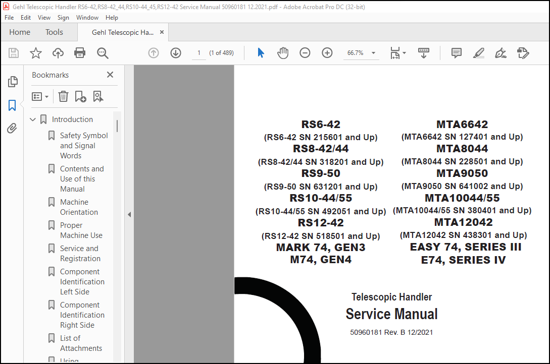
RS6-42
(RS6-42 SN 215601 and Up)
RS8-42/44
(RS8-42/44 SN 318201 and Up)
RS9-50
(RS9-50 SN 631201 and Up)
RS10-44/55
(RS10-44/55 SN 492051 and Up)
RS12-42
(RS12-42 SN 518501 and Up) MARK 74, GEN3 M74, GEN4
MTA6642
(MTA6642 SN 127401 and Up)
MTA8044
(MTA8044 SN 228501 and Up)
MTA9050
(MTA9050 SN 641002 and Up)
MTA10044/55
(MTA10044/55 SN 380401 and Up)
MTA12042
(MTA12042 SN 438301 and Up) EASY 74, SERIES III E74, SERIES IV
Chapter 1
INTRODUCTION
Safety Symbol and Signal Words This manual and decals on the machine warn of safety hazards and should be read and observed closely. Manitou Group, in cooperation with the Society of Automotive Engineers, has adopted this: This symbol is used throughout this operator’s manual and on the decals on the machine. It identifies potential safety hazards, which, if not properly avoided, could result in injury. When you see this symbol in this manual or on the machine, you are reminded to BE ALERT! Personal safety is involved!
- It is the owner’s or employer’s responsibility to fully instruct each operator in the proper and safe operation and maintenance of the machine. A storage location is provided behind the operator’s seat for storing the operator’s manual. After using the manual, return it to the storage container.
- This manual is considered a permanent part of the machine and should be with the machine at all times. If the machine is resold, include this operator’s manual as part of the sale. Replace this manual promptly if it becomes damaged, lost or stolen. Some illustrations in this manual may show doors, guards and shields open or removed for illustrative purposes only.
- BE SURE all doors, guards and shields are in their proper operating positions BEFORE starting the engine to operate the machine. Because of ongoing product improvements, information included in this manual may not exactly match the machine. Manitou Group reserves the right to modify and improve products at any time without notice or obligation.
TABLE OF CONTENTS:
Gehl Telescopic Handler RS6-42RS8-42_44RS10-44_45RS12-42 Service Manual 50960181 – PDF DOWNLOAD
INTRODUCTION 7
Safety Symbol and Signal Words . 7
Contents and Use of this Manual. 7
Machine Orientation . 8
Proper Machine Use. 8
Service and Registration . 8
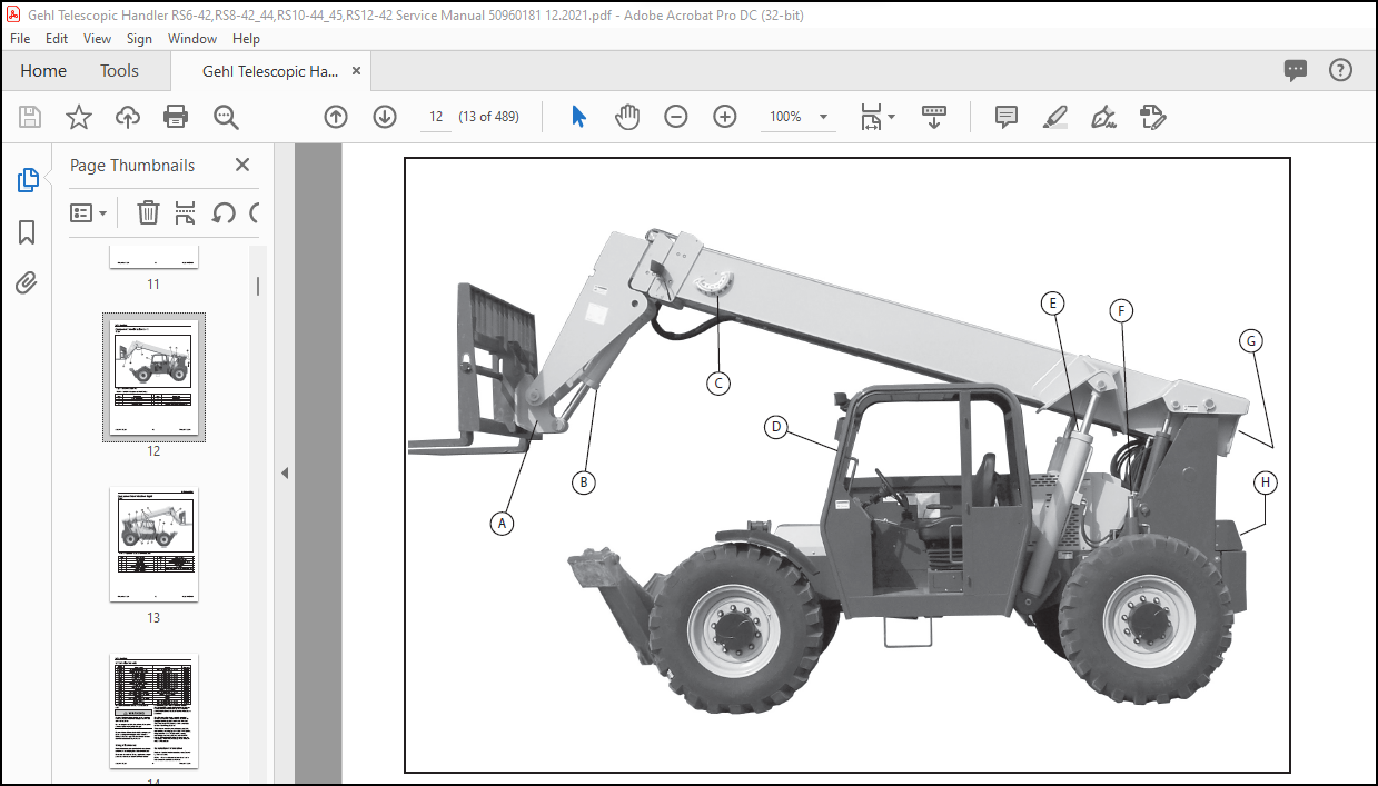
Component Identification Left Side. 12
Component Identification Right Side. 13
List of Attachments . 14
Using Attachments . 14
Manufacturer Information . 14
Indicator and Operation Symbols. 15
SAFETY 16
Safety Symbol and Signal Words . 16
Mandatory Safety Shutdown Procedure. 17
Before Operation Safety Reminders. 18
Operation Safety Reminders. 19
Provision for Stability/Avoiding Rollover Accidents . 22
Applications with Load-Handling Devices . 23
Suspended Load Safety Reminders . 23
Parking the Machine. 24
Electrical Energy . 25
Maintenance and Service Safety Practices. 25
Printed in U.S.A. 2 50960181/B1221
Battery Hazards. 27
Fire Hazards . 27
Additional Safety Equipment . 28
Crystalline Silica Exposure. 28
Personnel Work Platform (PWP) System. 29
Wireless Remote Battery Replacement. 30
Work Platform Design Requirements (Per ANSI/ITSDF B56.6 – 2016, Sec. 8.24). 31
Safety Decals . 32
New Decal Application. 32
LUBRICATION 38
General Information. 38
Types of Lubricants and Capacities . 38
Lubrication Points. 39
Filter Table . 41
MAINTENANCE 42
Maintenance Schedule . 42
Maintenance Interval . 44
Engine Maintenance. 44
Fuel System Maintenance. 54
Diesel Exhaust System (DEF) Maintenance. 59
Transmission Maintenance. 61
Axle Maintenance. 62
Hydraulic System Maintenance . 63
Tire and Wheel Maintenance . 65
Battery and Cable Maintenance . 68
HVAC/Air Conditioning Maintenance. 70
Check Instruments Operation. 71
Check General Machine Operation and Condition. 71
Check Personnel Work Platform (PWP) System (if used). 71
Storage . 73
PWP System Operational Troubleshooting. 74
POWERTRAIN 78
Engine (Cummins). 78
Engine (Deutz 74hp). 100
Engine (Deutz 120hp). 116
TRANSMISSION. 137
REAR AXLE . 151
Front Axle. 157
HYDRAULICS 167
Main Hydraulic Control Valve. 167
Main Gear Pump. 178
Steering Motor . 183
Lift Cylinder. 185
Slave Cylinder. 187
Frame Leveling Cylinder . 191
Tilt Cylinder. 194
Cylinder Repair. 198
Stabilizer Cylinder Removal and Installation. 207
Stabilizer Cylinder Repair. 210
Boom Extend Cylinder Removal and Installation (3-Section Boom) . 217
Printed in U.S.A. 4 50960181/B1221
Boom Extend Cylinder Removal and Installation (4-Section Boom) . 221
Hydraulic Testing and Adjustment Procedures. 225
HYDRAULIC SCHEMATICS 255
Hydraulic Schematic without PWP. 255
Hydraulic Schematic with PWP. 256
ELECTRICAL CONTROLS SYSTEMS 257
Electrical Control System General Information. 257
Control Modules. 258
Display, Indicators, and Controls. 259
Fuses, Relays, and Resistors. 266
Engine Diagnostic Trouble Codes (DTCs). 269
ELECTRICAL SCHEMATICS 283
Cummins Engine Electrical Schematic – (1 of 5) Start-up / Customer Digicode . 283
Cummins Engine Electrical Schematics – (1 of 5) Legends. 284
Cummins Engine Electrical Schematics – (2 of 5) CAN / ECU. 285
Cummins Engine Electrical Schematics – (2 of 5) Legends. 286
Cummins Engine Electrical Schematics – (3 of 5) Switch Operated Functions / Movement. 287
Cummins Engine Electrical Schematics – (3 of 5) Legends. 288
Cummins Engine Electrical Schematics – (4 of 5) Fan / Air-Conditioner and Wipers. 289
Cummins Engine Electrical Schematics – (4 of 5) Legends. 290
Cummins Engine Electrical Schematics – (5 of 5) Lighting. 291
Cummins Engine Electrical Schematics – (5 of 5) Legends. 292
Deutz Engine Electrical Schematic (120 hp engine – page 1 of 3). 293
Deutz Engine Electrical Schematic (120 hp engine – page 2 of 3). 294
Deutz Engine Electrical Schematic (120 hp engine – page 3 of 3). 295
Deutz Engine Electrical Schematics (74 hp engine – page 1 of 2). 296
Deutz Engine Electrical Schematics (74 hp engine – page 2 of 2). 297
CAB 298
Cab . 298
TELESCOPIC BOOM 316
General Information. 316
Boom Assembly. 316
Single and Double Leaf Chain Adjustments (3-Section Boom). 324
Inner Boom Section Removal and Installation (3-Section Boom). 324
Double Chain and Roller Bearing Replacement (3-Section Boom). 331
Single Chain and Roller Bearing Replacement (3-Section Boom). 334
Intermediate Boom Section Removal and Installation (3-Section Boom). 340
Boom Pad Replacement (3-Section Boom).. 346
Overview 4-Section Boom. 350
Boom Assembly Removal and Installation (4-Section Boom). 354
1st Intermediate Boom Section Removal and Installation (4-Section Boom). 358
2nd Intermediate Boom Section Removal and Installation (4-Section Boom). 366
Inner Boom Section Removal and Installation (4-Section Boom). 380
Boom Hydraulic Hose and Tube Replacement (4-Section Boom). 386
Boom Pad Overview (4-Section Boom). 403
Boom Pad Replacement (4-Section Boom) . 407
1st Intermediate Boom. 411
2nd Intermediate Boom Rear Pad Replacement. 420
2nd Intermediate Boom Front Pad Replacement . 428
Printed in U.S.A. 6 50960181/B1221
Inner Boom. 431
Overview Boom Chain and Rollers (4-Section Boom) . 440
Inner Boom Top Chain and Roller Replacement (4-Section Boom) . 442
Bottom Inner Boom Chain and Roller Replacement (4-Section Boom) . 452
2nd Intermediate Boom Chain and Roller Replacement (4-Section Boom). 460
Outer Boom Chain and Roller Replacement (4-Section Boom). 469
Boom Chain Adjustment (4-Section Boom). 474
SPECIFICATION 476
Machine Configuations. 476
Lifting Performance . 476
General Dimensions. 478
Multi-Functional Display. 479
Visual Indicators. 479
Steering System . 480
Braking System. 480
Electrical System . 480
Service Capacities. 480
Transmission Type . 481
Axles (Front and Rear). 482
Operator’s Station. 483
More products