$23
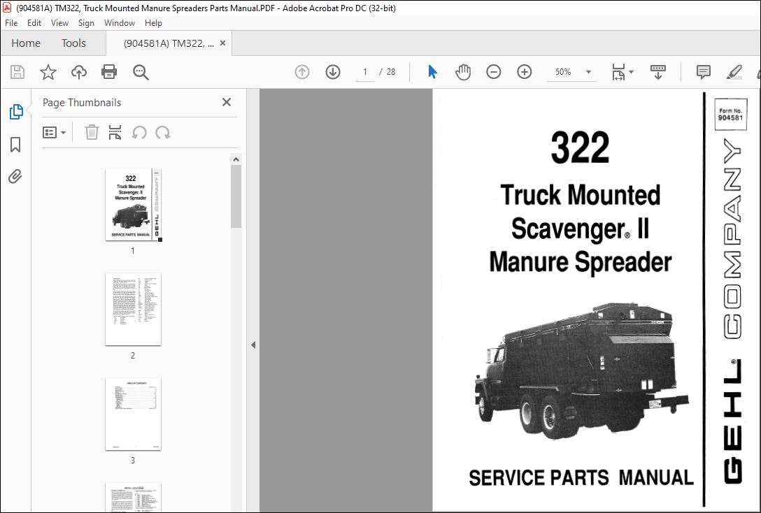
Gehl TM322, Truck Mounted Manure Spreaders Parts Manual (904581A) – PDF DOWNLOAD
Gehl TM322, Truck Mounted Manure Spreaders Parts Manual (904581A) – PDF DOWNLOAD
DESCRIPTION:
Gehl TM322 Truck Mounted Manure Spreaders Parts Manual (904581A) – PDF DOWNLOAD
Introduction:
- When ordering service parts, specify the correct part number, full description, quantity required, the unit model number and serial number. Numbers for this unit are stamped ona plate located on the Left side of the Rear Main Frame adjacent to the Rotor Drive Sheave.
- “Right” and “LefC.are determined from a podtion standing behind the unit and facing the tractor. From this position the Blower Outlet would then be on the “Left” side. G E H L: Company reserves the right to make changes or improvements in the design or construction of any part of the unit without incurring the obligation to install such changes on any unit previously delivered.
- Grease fittings and common attaching hardware, such as Cotter Pins, Set Screws, Wocxiruff Keys, Screws, Nuts, etc., are included in the parts list, indented below the part it is (they are) associated with, but NOT illustrated, except where a particular routing or special fastening arrangement MUST be maintained.
- The hardware listed is for mounting purposes and is NOT included when the part is ordered for replacement. Refer to the abbreviations table for the various fastener descriptions. For the part number of common hardware, refer to the Attaching Hardware Table located on the Inside Back Cover. Standard hardware torque values ·are also provided on the same page.
TABLE OF CONTENTS:
Gehl TM322 Truck Mounted Manure Spreaders Parts Manual (904581A) – PDF DOWNLOAD
Introduction . . . . . . . . . . . . . . . . . . . . . . . . . . . . . . . . . . . . . . Inside Front Cover
Table of Contents . . . . . . . . . . . . . . . . . . . . . . . . . . . . . . . . . . . . . . . . . . . . 1
Decal Locations . . . . . . . . . . . . . . . . . . . . . . . . . . . . . . . . . . . . . . . . . . . . 2-3
Ex])eller & Drives ……………………………………. 4-5
Ex])eller Gate & Liner . . . . . . . . . . . . . . . . . . . . . . . . . . . . . . . . . . . . . . . . . 6-7
Hydraulics . . . . . . . . . . . . . . . . . . . . . . . . . . . . . . . . . . . . . . . . . . . . . . . 8-9
Drive Shaft & Drive Guards . . . . . . . . . . . . . . . . . . . . . . . . . . . . . . . . . . . . 10-11
Discharge Auger . . . . . . . . . . . . . . . . . . . . . . . . . . . . . . . . . . . . . . . . . . . . . 12
Hydraulic Cylinders . . . . . . . . . . . . . . . . . . . . . . . . . . . . . . . . . . . . . . . . . . . 13
Completing Parts . . . . . . . . . . . . . . . . . . . . . . . . . . . . . . . . . . . . . . . . . . 14-17
Hydraulic System .•….•…….•…………..•…………… 14-15
Mechanical Drive . • . • . . • . . . . . . . . . . . . . . . . . . . . . • . . . . . . . . . . . . . . . . . . 16
Fenders & BWllper • • • . • . • • . • . • • • • • • . • • • • • • • • • • • • . . • . • • . • • . . . . • • • • 17
Accessories ……………………………………… 18-21
Splash Guards . . . . . . . . . . . . . . . . . . . . • . . . . . . . . . . . . . . . . . . . . . . . . . . . . 18
Hydraulic Lid . . . . . . . . . . . . . . . • . . . . . . . . . . . . . . . . . . . . . . . . . . . . . . . . . . 19
Light Kit . . • . . . . . . . . • . . . . . . . . . . . . . . . . . . . . . . . . . . . . . . . . . . . . . . . . 20
Mud Flaps • • . . . . • . . . • . • . . . . • . • . . • . . . • . . . . . • . . . . . . . . . . . . . . . . . . 21
Numerical Index ……………………………………. 22-23
Standard Hardware Torque S])ecifications . . . . . . . . . . . . . . . . . . . . . . Inside Back Cover
Printed
IMAGES PREVIEW OF THE MANUAL:
More products