$22
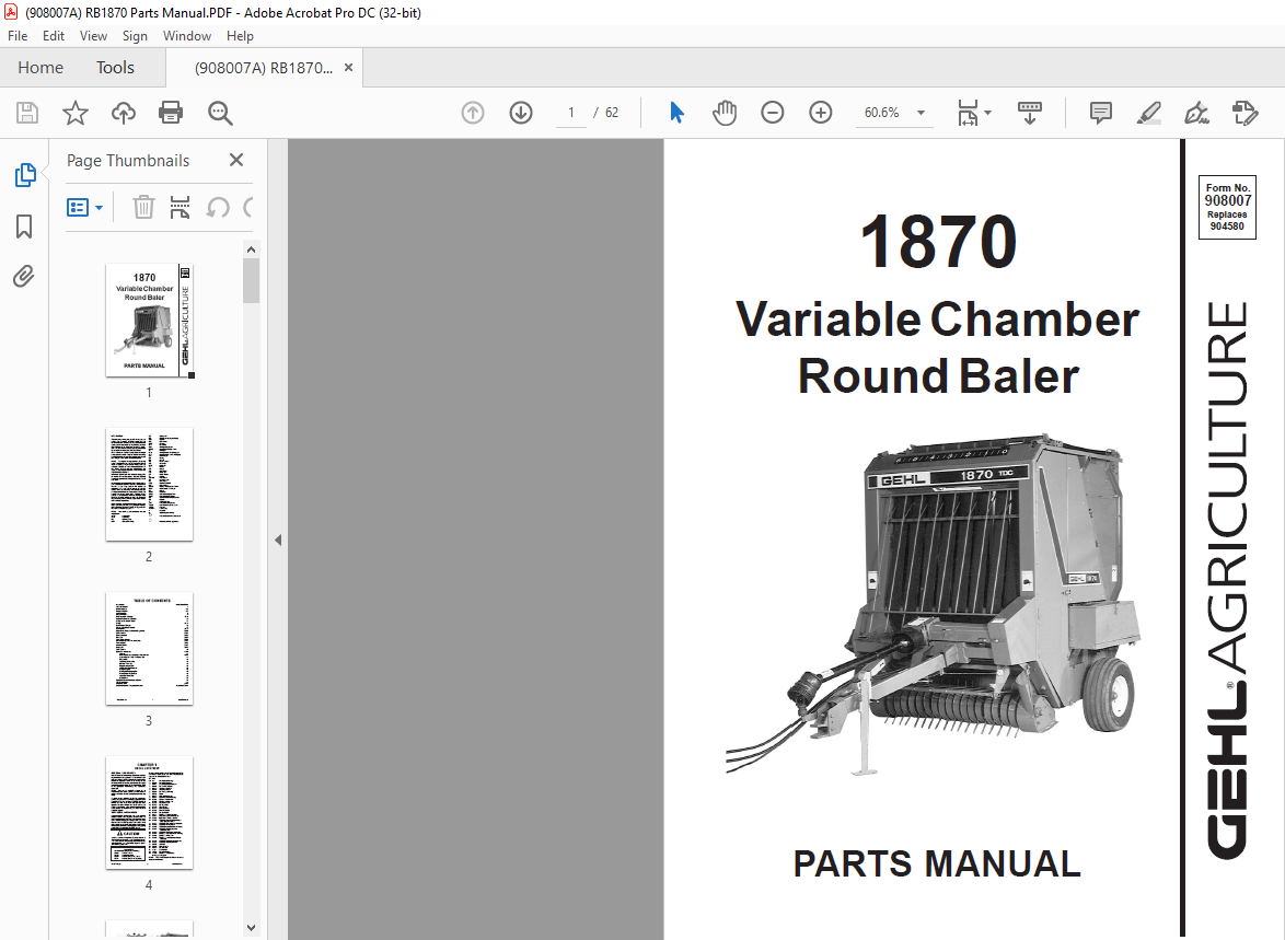
Gehl Variable Chamber Round Baler 1870 Parts Manual(908007) – PDF DOWNLOAD
Gehl Variable Chamber Round Baler 1870 Parts Manual(908007) – PDF DOWNLOAD
TABLE OF CONTENTS:
Gehl Variable Chamber Round Baler 1870 Parts Manual(908007) – PDF DOWNLOAD
Introduction Inside Front Cover
Table of Contents 1
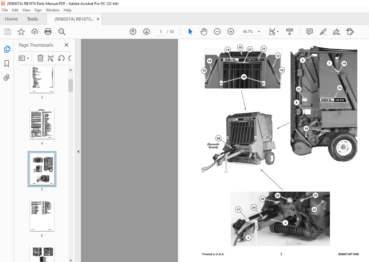
Decal Locations 2-5
Frame & Fenders 6-7
Left Twine Box 8
Right Twine Box 9
Drawbar, Axles & Ramps 10-11
Implement Driveline & Gearbox 12
Pickup Lift & Overfill Clutch 13
Pickup 14-15
Bale Starter & Scraper 16
Shuttle & Bale Size Indicator 17
Roller Drives 18-19
Upper Belts, Rollers & Related Components 20-21
Lower Rollers 22-23
Gate Hydraulics 24-25
Rear Gate 26-27
Total Density Control 28-31
Cross Frame & Twine Tie Mechanism 32-33
Transmissions 34-35
Universal Drives 35-37
Hitchjacks 38-39
TDC Cylinder 40
Options & Accessories 41-50
Actuator 41
1000 RPM Conversion Kit & Universal Drive 42-43
Manual-Electric Twine Tie Control Kit 44
Control Box 45
Auto-Electric Twine Tie 46
Crowder Wheel Kit 47
Stripper Assembly Kit 48
Audible Bale Size Indicator 48
Transport Lights 48
Packing Roller Lagging Kit 49
Packing Roller Scraper Kit 49
Automatic Chain Oiler 50
Safety Chain 50
Sprocket & Roller Part Number Guide 51
Alphabetical Index 52
Numerical Index 53-57
Standard Hardware Torque Specifications Inside Back Cover
DESCRIPTION:
Gehl Variable Chamber Round Baler 1870 Parts Manual(908007) – PDF DOWNLOAD
Introduction:
- When ordering service parts, please specify the correct part number, full description, quantity required, unit model number, and serial number. For your safety and continued proper operation, only use genuine GEHL service parts.
- The Manure Spreader model and serial numbers for this unit are located on a decal on the left side of the main frame at the front left corner of the box. Please note that “right” and “left” are determined from a position standing behind the Manure Spreader.
- GEHL Company reserves the right to make changes or improvements to the design or construction of any part of the unit without incurring the obligation to install such changes on any previously delivered units.
- Please refer to the abbreviations table located on this page for the various fastener descriptions. Standard attaching hardware torque values are provided on the inside back cover.
- In the exploded view parts list, Reference Numbers may have additional information following the Reference Number. A tear drop symbol indicates an application of a “wet” product such as oil, and the number inside the tear drop will correspond to the description in the Parts List. A number inside a hexagon will be the torque value required, in foot-pounds, on the associated Reference Number. Items shown in the parts list that do not have Reference Numbers are shown for reference purposes only and are NOT available for purchase.
- Unless otherwise specified, all cap screws or bolts are Grade 5, zinc-plated. Hexagon nuts for Grade 5 cap screws or bolts are Grade B, while hexagon nuts for other cap screws or bolts are Grade A.
GENERAL INFORMATION:
- Decal location information is provided to assist in the proper selection and application of new decals, in the event the original decals become damaged or the machine is repainted. Please refer to the listing for the illustration reference number, part number, description, and quantity of each decal provided in the kit. Refer to the appropriate illustrations for replacement locations.
- To ensure proper selection for correct replacement decals, compare all of the various close-up location illustrations of the machine BEFORE starting to refinish the unit. Then, circle each pictured decal applicable to your machine, while checking off its part number in the listing. After verifying all the decals needed for replacement, set aside any unneeded decals for disposal.
IMAGES PREVIEW OF THE MANUAL:

More products