$34
Gehl VT320 Mustang Manitou 3200VT Track Loader Service Manual 50940548 – PDF DOWNLOAD
Gehl VT320 Mustang Manitou 3200VT Track Loader Service Manual 50940548 – PDF DOWNLOAD
FILE DETAILS:
Gehl VT320 Mustang Manitou 3200VT Track Loader Service Manual 50940548 – PDF DOWNLOAD
Language : English
Pages : 368
Downloadable : Yes
File Type : PDF
Size: 49.7 MB
IMAGES PREVIEW OF THE MANUAL:
DESCRIPTION:
Gehl VT320 Mustang Manitou 3200VT Track Loader Service Manual 50940548 – PDF DOWNLOAD
SAFETY:
• Before operating the machine, first read and study the safety information in this manual. Be sure that anyone who operates or works on the machine is familiar with the safety precautions. This includes providing translations of the warnings and instructions for operators who are not fluent in reading English.• It is essential that operators be thoroughly trained in the safe operation of the machine and load handling. Operators must not be physically or mentally impaired. Do not allow minors or unqualified personnel to operate the machine, or to be near the machine unless they are properly supervised. It is recommended that the operator be capable of obtaining a valid motor vehicle operator’s license.• Do not use the machine for any application or purpose other than those described in this manual, or in manuals supplied with any attachments used with the machine.• Use of the machine is subject to certain hazards that cannot be eliminated by mechanical means, but only by exercising intelligence, care and common sense. Such hazards include: hillside operation, overloading, load instability, poor maintenance, and using the machine for a purpose for which it was not intended or designed.• Manitou always takes operator’s safety into consideration during the design process. Guards and shields are provided, which protect the operator and bystanders from moving parts and other hazards. Operators must be alert, however, because some areas cannot be guarded or shielded without preventing or interfering with proper operation.• Different applications may require optional safety equipment. Users must evaluate the worksite hazards and equip the machine and the operator as necessary. The information in this manual does not replace any applicable safety rules and laws. Before operating the machine, learn the rules and laws for the local area. Make sure the machine is equipped as required according to these rules/laws.
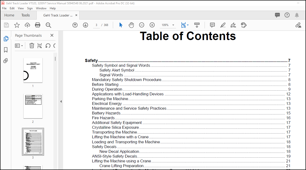
TABLE OF CONTENTS:
Gehl VT320 Mustang Manitou 3200VT Track Loader Service Manual 50940548 – PDF DOWNLOAD
Table of Contents…………………………………………………………………………………. 3
Safety…………………………………………………………………………………………… 9
Safety Symbol and Signal Words………………………………………………………………….. 9
Safety Alert Symbol………………………………………………………………………… 9
Signal Words………………………………………………………………………………. 9
Mandatory Safety Shutdown Procedure……………………………………………………………… 10
Before Starting……………………………………………………………………………….. 10
During Operation………………………………………………………………………………. 11
Applications with Load-Handling Devices………………………………………………………….. 14
Parking the Machine……………………………………………………………………………. 15
Electrical Energy……………………………………………………………………………… 15
Maintenance and Service Safety Practices…………………………………………………………. 15
Battery Hazards……………………………………………………………………………….. 17
Fire Hazards………………………………………………………………………………….. 18
Additional Safety Equipment…………………………………………………………………….. 19
Crystalline Silica Exposure…………………………………………………………………….. 19
Transporting the Machine……………………………………………………………………….. 19
Lifting the Machine with a Crane………………………………………………………………… 19
Loading and Transporting the Machine…………………………………………………………….. 20
Safety Decals…………………………………………………………………………………. 20
New Decal Application………………………………………………………………………. 20
ANSI-Style Safety Decals……………………………………………………………………….. 21
Lifting the Machine using a Crane……………………………………………………………….. 23
Crane Lifting Preparation…………………………………………………………………… 23
Loading and Transporting the Machine on a Transport Vehicle………………………………………… 24
Loading and Securing the Machine…………………………………………………………….. 24
Introduction……………………………………………………………………………………… 27
Contents and Use of this Manual…………………………………………………………………. 27
Machine Orientation……………………………………………………………………………. 27
Component Identification……………………………………………………………………….. 28
Machine Model and Serial Number Locations………………………………………………………… 29
Component Serial Numbers……………………………………………………………………. 29
ROPS/FOPS Certification Label…………………………………………………………………… 29
Indicator and Operation Symbols…………………………………………………………………. 30
Machine Controls and Operation………………………………………………………………….. 31
Maintenance………………………………………………………………………………………. 33
Maintenance Schedule…………………………………………………………………………… 34
Checks, Cleaning and Inspection……………………………………………………………… 34
Leakage Check……………………………………………………………………………… 35
Lubrication and Filter Changes………………………………………………………………. 36
Functional Check…………………………………………………………………………… 36
Engine Maintenance…………………………………………………………………………….. 37
Engine Access……………………………………………………………………………… 37
Closing Engine Covers…………………………………………………………………… 37
Engine Oil………………………………………………………………………………… 38
Checking Engine Oil Level……………………………………………………………….. 38
Changing Engine Oil and Filter…………………………………………………………… 39
Engine Air Filters…………………………………………………………………………. 40
Changing Air Filter Elements………………………………………………………………… 41
Engine Cooling System………………………………………………………………………. 41
Checking Coolant Level………………………………………………………………….. 41
Cleaning Radiator Fins………………………………………………………………….. 42
Draining/Refilling Cooling System………………………………………………………… 42
Belt Maintenance…………………………………………………………………………… 43
Engine Accessory Belt…………………………………………………………………… 43
Air Conditioning Belt…………………………………………………………………… 44
Belt Installation………………………………………………………………………. 44
Diesel Exhaust Fluid (DEF) Service………………………………………………………………. 46
Diesel Exhaust Fluid (DEF) Level…………………………………………………………….. 46
DEF Dosing Unit Filter Replacement…………………………………………………………… 46
Fuel System Maintenance………………………………………………………………………… 48
Adding Fuel……………………………………………………………………………….. 48
Water Separator Inspection/Maintenance……………………………………………………….. 49
Changing Water Separator and Fuel Filter……………………………………………………… 50
Hydraulic System Maintenance……………………………………………………………………. 51
Checking Hydraulic Oil Level………………………………………………………………… 51
Changing Hydraulic Oil and Filter……………………………………………………………. 52
Hydraulic Hose Maintenance……………………………………………………………………… 54
Travel Motor Maintenance……………………………………………………………………….. 55
Travel Motor Gearbox Oil……………………………………………………………………. 55
Track Maintenance……………………………………………………………………………… 55
Track Replacement………………………………………………………………………….. 55
General Lubrication……………………………………………………………………………. 56
Tilting ROPS/FOPS……………………………………………………………………………… 57
Raising ROPS/FOPS………………………………………………………………………….. 57
Lowering ROPS/FOPS…………………………………………………………………………. 58
Electrical System……………………………………………………………………………… 59
Batteries…………………………………………………………………………………. 59
Using a Booster Battery (Jump-Starting)………………………………………………………. 60
Fuses and Relays…………………………………………………………………………… 60
Fuses/Relays…………………………………………………………………………… 60
Engine Compartment Relays/Fuses – (SN 330101 and Up)…………………………………………… 61
Engine Compartment Relays/Fuses – (SN 330100 and Before)……………………………………….. 62
Power-A-Tach Relay……………………………………………………………………… 63
Optional 14-Pin Connector Fuses/Relays……………………………………………………. 63
Rearview Camera Fuse……………………………………………………………………….. 63
Long-Term Storage……………………………………………………………………………… 64
Before Storage…………………………………………………………………………….. 64
After Storage……………………………………………………………………………… 64
Air Conditioning Maintenance……………………………………………………………………. 65
Air Conditioning Filters……………………………………………………………………. 65
Cab Air Filter…………………………………………………………………………. 65
Outside Air Intake Filter……………………………………………………………….. 65
Windshield Washer Reservoir…………………………………………………………………….. 66
Final Shutdown / Decommissioning………………………………………………………………… 66
Before Disposal……………………………………………………………………………. 66
Machine Disposal…………………………………………………………………………… 66
Engine…………………………………………………………………………………………… 67
General Information……………………………………………………………………………. 67
Engine Access…………………………………………………………………………………. 67
Closing Engine Covers………………………………………………………………………. 67
Deutz SerDia Connection/Software………………………………………………………………… 68
Engine Maintenance…………………………………………………………………………….. 69
Engine Cooling System………………………………………………………………………….. 69
Engine Removal/Installation…………………………………………………………………….. 69
Engine Removal…………………………………………………………………………….. 69
Engine Installation………………………………………………………………………… 79
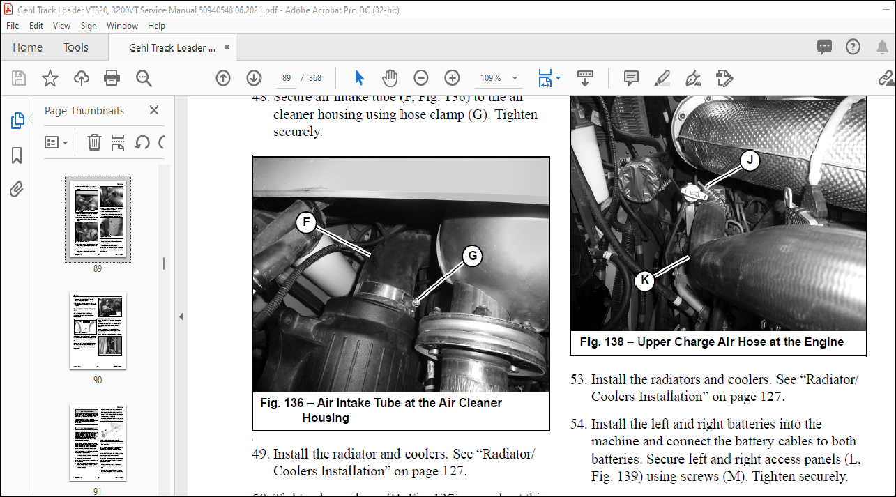
Diesel Exhaust Fluid (DEF) Service………………………………………………………………. 90
Diesel Exhaust Fluid (DEF) Level…………………………………………………………….. 90
DEF Dosing Unit Filter Replacement…………………………………………………………… 90
Fuel System Maintenance………………………………………………………………………… 92
Adding Fuel……………………………………………………………………………….. 92
Water Separator Inspection/Maintenance……………………………………………………….. 93
Changing Water Separator and Fuel Filter……………………………………………………… 94
Engine Troubleshooting…………………………………………………………………………. 95
Engine Error Codes…………………………………………………………………………. 97
Cooling System…………………………………………………………………………………….115
General Information…………………………………………………………………………….115
Radiator/Coolers Removal………………………………………………………………………..119
Radiator/Coolers Installation……………………………………………………………………127
Hydrostatic Drive System……………………………………………………………………………135
General Information…………………………………………………………………………….135
General Hydraulic Service Notes………………………………………………………………….135
Hydraulic Oil Analysis………………………………………………………………………….135
Hydrostatic Drive Pump………………………………………………………………………….135
Hydrostatic Charge Pressure Test and Adjustment………………………………………………..138
Hydrostatic DA Pressure Test and Adjustment……………………………………………………138
Hydrostatic Pump Relief Valves…………………………………………………………………..139
Hydrostatic Pump High Pressure Test…………………………………………………………..140
Travel Drive Troubleshooting…………………………………………………………………….140
Travel Drive Joystick Lockout Valve Test………………………………………………………141
Neutral Centering Check/Adjustment……………………………………………………………….143
Straight Tracking Adjustment…………………………………………………………………….145
Forward Straight Tracking Adjustment………………………………………………………….145
Reverse Straight Tracking Adjustment………………………………………………………….146
Hydrostatic Pump Removal and Installation…………………………………………………………148
Hydrostatic Pump Removal…………………………………………………………………….148
Hydrostatic Drive Pump Installation…………………………………………………………..152
Hydrostatic Pump Drive Coupling Removal and Installation……………………………………………155
Installation……………………………………………………………………………….156
Travel Motors………………………………………………………………………………….156
Travel Motor Maintenance…………………………………………………………………….159
Travel Motor Removal/Installation…………………………………………………………….159
Travel Motor Removal…………………………………………………………………….159
Travel Motor Installation………………………………………………………………..161
Travel Drive High-Speed Troubleshooting…………………………………………………………..163
Travel Drive High-Speed (Pilot) Valve Test…………………………………………………….163
Tracks………………………………………………………………………………………..166
Rubber Track Use Cautions and Tips……………………………………………………………167
Sprocket Tooth Wear and Track Life……………………………………………………………168
Track Replacement…………………………………………………………………………..169
Track Removal…………………………………………………………………………..169
Track Installation………………………………………………………………………170
IdealTrax™ Track Tensioning System……………………………………………………………173
Track Tensioning Malfunctions………………………………………………………………..174
Track Tension Cylinder Internal Leakage Test……………………………………………….174
Track Tension (Pilot) Valve Test………………………………………………………….174
Parking (SAHR) Brake Malfunctions………………………………………………………………..175
Parking Brake (Pilot) Valve Test……………………………………………………………..176
Hydrostatic Drive System Troubleshooting………………………………………………………….179
Work Hydraulics……………………………………………………………………………………183
General Information…………………………………………………………………………….183
General Hydraulic Service Notes………………………………………………………………….183
Hydraulic Oil Analysis………………………………………………………………………….183
Hydraulic Hoses/Tubes……………………………………………………………………….190
Seals……………………………………………………………………………………..190
Main Pressure Test and Adjustment………………………………………………………………..190
Main Pressure Test………………………………………………………………………….190
Main Pressure Adjustment…………………………………………………………………….191
Hydraulic Gear Pump…………………………………………………………………………….192
Hydraulic Gear Pump Removal………………………………………………………………….193
Hydraulic Gear Pump Installation……………………………………………………………..194
Control Valve………………………………………………………………………………….195
Main Control Valve Removal…………………………………………………………………..196
Main Control Valve Installation………………………………………………………………196
Tilt/Lift Cylinder Circuits Components……………………………………………………………197
Tilt/Lift Cylinder Service/Tests…………………………………………………………………199
Inspection…………………………………………………………………………………199
Cylinder Rod/Base End Pressure Tests………………………………………………………….199
Tilt Cylinder Base End Pressure Test………………………………………………………199
Tilt Cylinder Rod End Pressure Test……………………………………………………….200
Lift Cylinder Base End Pressure Test………………………………………………………200
Lift Cylinder Rod End Pressure Test……………………………………………………….201
Lift/Tilt Relief Pressure Adjustment………………………………………………………….202
Cylinder Drift Tests………………………………………………………………………..203
Tilt Cylinder Drift Test…………………………………………………………………203
Lift Cylinder Drift Test…………………………………………………………………203
Cylinder Internal Leakage Tests………………………………………………………………203
Tilt Cylinder Internal Leakage Test……………………………………………………….203
Lift Cylinder Internal Leakage Test……………………………………………………….204
Cylinder Cycle Time Test…………………………………………………………………….204
Lower the Lift Arm………………………………………………………………………204
Raise the Lift Arm………………………………………………………………………205
Dump the Bucket/Attachment Hitch………………………………………………………….205
Roll the Bucket/Attachment Hitch Back……………………………………………………..205
Hydraulic Cylinder Disassembly/ Assembly………………………………………………………….206
Cylinder Disassembly………………………………………………………………………..206
Cylinder Assembly…………………………………………………………………………..206
Bleeding Air After Cylinder Installation………………………………………………………206
Work Hydraulics Tests and Solenoid Valves…………………………………………………………207
Hydraloc Safety Interlock Solenoid Valve Test………………………………………………….207
Self-Leveling Cancel (Disable) Valve and Test………………………………………………….210
Hydraglide…………………………………………………………………………………….212
Hydraglide/Float Valve Solenoid Test………………………………………………………….213
Hydraglide Accumulator………………………………………………………………………215
Solenoid Valve Disassembly/ Reassembly……………………………………………………………216
Work Hydraulics Troubleshooting………………………………………………………………….217
Hydraulic Schematic………………………………………………………………………………..219
(Gehl SN 0040301 and Up; Mustang SN 0060301 and Up; All Manitou)…………………………………….219
Hydraulic Schematic – (Gehl SN 0040300 and Before; Mustang SN 0060300 and Before)……………………..220
Electrical Control System…………………………………………………………………………..221
Electrical Control System General Information……………………………………………………..221
CAN System General Information……………………………………………………………….221
Control Modules………………………………………………………………………………..222
Machine Control Unit (MCU)…………………………………………………………………..222
Keypads……………………………………………………………………………………225
Engine Control Unit (ECU)……………………………………………………………………227
Display/Indicators/Controls………………………………………………………………….227
Multi-Function Display…………………………………………………………………..227
CAN System Service/Computer Connection……………………………………………………………228
J1939 Data Connector………………………………………………………………………..228
CAN/Computer Connection Harnesses…………………………………………………………….228
Service Adapter Harness………………………………………………………………….228
Deutz Engine CAN/Computer Connection Harness (SerDia)…………………………………………..229
Operation/Controller Area Network (CAN) Functional Organization……………………………………..230
Operation/CAN Function Organization Overview…………………………………………………..230
HydralocTM (Safety Interlock) Functional Detail………………………………………………..231
Ignition/Starting Functional Detail…………………………………………………………..232
Operation Functional Detail………………………………………………………………….234
Lift Arm Functional Detail…………………………………………………………………..235
Drive System Functional Detail……………………………………………………………….238
Auxiliary Hydraulics Functional Detail………………………………………………………..240
Warning Indicators Functional Detail………………………………………………………….242
Lighting Functional Detail…………………………………………………………………..244
Accessories and Options Functional Detail…………………………………………………………245
CAN/Control System Troubleshooting……………………………………………………………….249
Inputs/Outputs Detail……………………………………………………………………….249
Inputs Detail…………………………………………………………………………..249
Outputs Detail………………………………………………………………………….257
Indicator Lamp Troubleshooting…………………………………………………………………..267
Electrical System………………………………………………………………………………….269
Batteries……………………………………………………………………………………..269
Power Distribution……………………………………………………………………………..278
Power Distribution Module Fuse Socket Test…………………………………………………….278
Main Power Relay……………………………………………………………………………278
Relay Testing………………………………………………………………………………278
Machine Test……………………………………………………………………………278
Bench Test……………………………………………………………………………..278
Glow Relay Solenoid Test………………………………………………………………………..279
Power-A-Tach Relay Solenoid Test…………………………………………………………………280
Control Modules………………………………………………………………………………..281
Lighting………………………………………………………………………………………281
Work Light Bulb Replacement………………………………………………………………….281
Tail Light Bulb Replacement………………………………………………………………….282
Dome Light Bulb Replacement………………………………………………………………….283
Wire Harness Diagrams………………………………………………………………………………285
Chassis Wire Harness Diagram – (Gehl SN 0040301 and Up; Mustang SN 0060301 and Up; all Manitou)…………285
Chassis Wire Harness Diagram – (Gehl SN 0040300 and Before; Mustang SN 0060300 and Before)……………..287
Engine Wire Harness Diagram – (Gehl SN 0040301 and Up; Mustang SN 0060301 and Up; all Manitou)………….289
Engine Wire Harness Diagram – (Gehl SN 0040300 and Before; Mustang SN 0060300 and Before)………………292
ROPS/FOPS (Cab) Wire Harness Diagram – (Gehl SN 0040301 and Up; Mustang SN 0060301 and Up; all Manitou)….295
ROPS/FOPS (Cab) Wire Harness Diagram – (Gehl SN 0040300 and Before; Mustang SN 0060300 and Before)………296
Operator’s Seat Wire Harness Diagram – (Later Machines)…………………………………………….297
Operator’s Seat Wire Harness Diagram – (Early Machines)…………………………………………….299
Electrical Schematics………………………………………………………………………………301
Chassis – (Gehl SN 0040301 and Up; Mustang SN 0060301 and Up; all Manitou)……………………………301
Electrical Schematic – Chassis – (Gehl SN 0040300 and Before; Mustang SN 0060300 and Before)……………303
Electrical Schematic – Engine – (Gehl SN 0040301 and Up; Mustang SN 0060301 and Up; all Manitou)………..305
Electrical Schematic – Engine – (Gehl SN 0040300 and Before; Mustang SN 0060300 and Before)…………….307
Electrical Schematic – Rear Door…………………………………………………………………309
Electrical Schematic – ROPS/FOPS (Cab)……………………………………………………………310
Electrical Schematic – Seat……………………………………………………………………..311
Electrical Schematic – Road Lights……………………………………………………………….313
Electrical Schematic – 14-Pin Connector…………………………………………………………..314
Lift Arm………………………………………………………………………………………….315
Lift Arm Support……………………………………………………………………………….315
Engage Lift Arm Support……………………………………………………………………..315
Disengage Lift Arm Support…………………………………………………………………..316
Lift Arm Alignment Stops………………………………………………………………………..317
Tilt Stop Adjustment……………………………………………………………………………318
Lift Arm Removal……………………………………………………………………………….320
Lift Arm Installation…………………………………………………………………………..324
ROPS/FOPS/Cab……………………………………………………………………………………..327
Tilting ROPS/FOPS………………………………………………………………………………327
Raising ROPS/FOPS…………………………………………………………………………..327
Lowering ROPS/FOPS………………………………………………………………………….328
ROPS/FOPS Removal………………………………………………………………………………328
ROPS/FOPS Installation………………………………………………………………………….336
HVAC System……………………………………………………………………………………….343
Air Conditioning Refrigerant Recovery…………………………………………………………….347
Air Conditioning System Port Access…………………………………………………………..347
Air Conditioning System Charging…………………………………………………………………347
Specifications…………………………………………………………………………………….349
Fluids/Lubricants Types and Capacities……………………………………………………………349
Dimensions…………………………………………………………………………………….351
Payloads/Capacities…………………………………………………………………………….353
Weights……………………………………………………………………………………….354
Track Drive……………………………………………………………………………………354
Coolant Compound Table………………………………………………………………………….354
Engine………………………………………………………………………………………..355
Hydraulic System……………………………………………………………………………….356
General……………………………………………………………………………………356
Drive Hydraulics……………………………………………………………………………356
Pumps……………………………………………………………………………………..357
Cylinders………………………………………………………………………………….357
Forces and Cycle Times………………………………………………………………………358
Electrical System………………………………………………………………………………358
Sound Power/Pressure Levels……………………………………………………………………..358
Features………………………………………………………………………………………359
Standard Features………………………………………………………………………………359
Optional Features………………………………………………………………………………359
Common Materials and Densities…………………………………………………………………..360
Index…………………………………………………………………………………………….361
Torque Specifications………………………………………………………………………………365
More products