$33
Gehl Wheel Steer 521 Operators Manual 909881 – PDF DOWNLOAD
Gehl Wheel Steer 521 Operators Manual 909881 – PDF DOWNLOAD
IMAGES PREVIEW OF THE MANUAL:
DESCRIPTION:
Gehl Wheel Steer 521 Operators Manual 909881 – PDF DOWNLOAD
Introduction
1 Notes on this operation manual
- This operation manual contains important information on how to work safely, correctly, and economically with the wheel loader model 521. Therefore, it aims not only at new operators but is also a reference for experienced ones. It helps to avoid dangerous situations and reduces repair costs and downtimes. Furthermore, following the instructions in the operation manual increases the reliability and service life of the vehicle.
- This is why the operation manual must always be kept at hand in the vehicle. Your own safety, as well as the safety of others, depends to a great extent on how the vehicle is moved and operated. Therefore, carefully read and understand this operation manual prior to the first drive. This operation manual will help to familiarize yourself more easily with the vehicle, thereby enabling you to use it more safely and efficiently.
- General safety instructions are given in Section 2 of this operation manual. The owner and the operators of the vehicle must know and follow them at all times. As a rule, keep the following in mind: Prudent and careful work is the best protection against accidents! Special safety instructions with direct reference to the service, function, and operation of the vehicle are given right before the procedure to follow in the respective sections.
- This is to make sure that these safety instructions are read and followed when needed. Operational safety and readiness of the vehicle do not only depend on your skill but also on maintenance and service of the vehicle. This is why regular maintenance and service work is absolutely necessary.
- Extensive maintenance and repair work must always be carried out by an expert with appropriate training. Insist on using original spare parts when carrying out maintenance and repair work. This ensures operational safety and readiness of your vehicle and maintains its value. Your dealer will be pleased to answer any further questions regarding the vehicle or the operation manual.
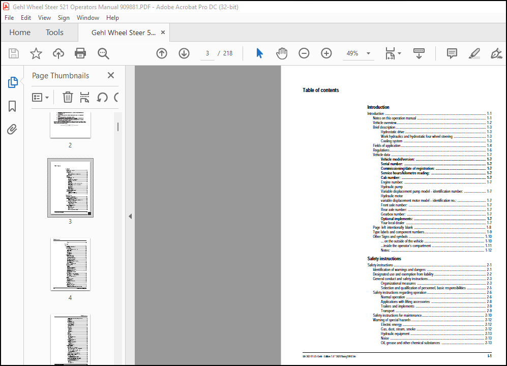
TABLE OF CONTENTS:
Gehl Wheel Steer 521 Operators Manual 909881 – PDF DOWNLOAD
Introduction
Introduction 1-1
Notes on this operation manual 1-1
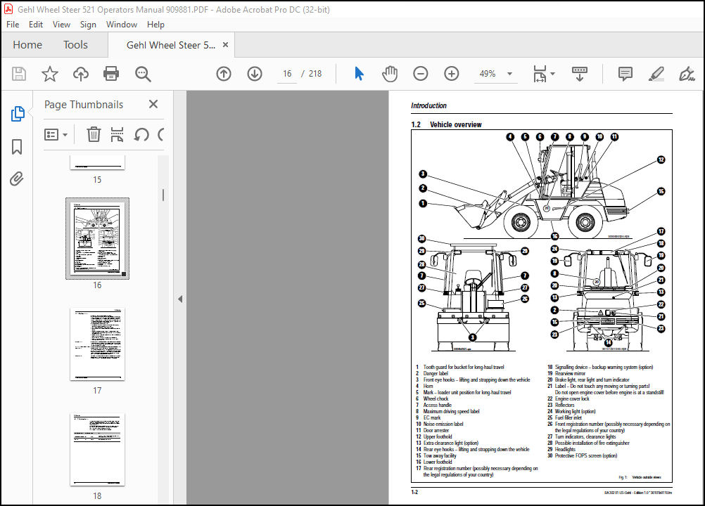
Vehicle overview 1-2
Brief description 1-3
Hydrostatic drive 1-3
Work hydraulics and hydrostatic four wheel steering 1-3
Cooling system 1-3
Fields of application 1-4
Regulations 1-6
Vehicle data 1-7
Vehicle model/version: 1-7
Serial number: 1-7
Commissioning/date of registration: 1-7
Service hours/kilometre reading: 1-7
Cab number: 1-7
Engine number: 1-7
Hydraulic pump
Variable displacement pump model – identification number: 1-7
Hydraulic motor
variable displacement motor model – identification no : 1-7
Front axle number: 1-7
Rear axle number: 1-7
Gearbox number: 1-7
Optional implements: 1-7
Your local dealer 1-7
Page left intentionally blank 1-8
Type labels and component numbers 1-9
Other Signs and symbols 1-10
on the outside of the vehicle 1-10
inside the operator’s compartment 1-11
Notes: 1-12
Safety instructions
Safety instructions 2-1
Identification of warnings and dangers 2-1
Designated use and exemption from liability 2-2
General conduct and safety instructions 2-3
Organizational measures 2-3
Selection and qualification of personnel, basic responsibilities 2-5
Safety instructions regarding operation 2-6
Normal operation 2-6
Applications with lifting accessories 2-8
Trailers and implements 2-9
Transport 2-9
Safety instructions for maintenance 2-10
Warning of special hazards 2-12
Electric energy 2-12
Gas, dust, steam, smoke 2-12
Hydraulic equipment 2-13
Noise 2-13
Oil, grease and other chemical substances 2-13
Table of contents
I-2 BA 302 01 US-Gehl – Edition 1 0 * 30201busg10IVZ fm
Table of contents
Battery 2-13
Tyres 2-13
Operation
Operation 3-1
Overview of cab 3-2
Overview: switches, levers and consoles 3-4
Taking into service 3-6
Safety instructions 3-6
Taking the vehicle into service for the first time 3-6
Important information 3-6
Running-in period 3-6
Checklists 3-7
Start-up checklist 3-7
Operation checklist 3-8
Parking checklist 3-8
Driving the vehicle 3-9
Overview of control elements 3-9
Preheating start switch [76] 3-9
Drive range selector [77] 3-9
Driving direction tip switch [72/75] 3-10
Accelerator pedal [25] 3-10
Manual throttle lever [71] (option) 3-11
Brake/inching pedal [27] 3-11
Control lever [84] – low-speed control (option) 3-12
Parking brake [24] 3-12
Multifunctional lever [26] 3-13
Overview Telltales and warning lights 3-15
Before starting the engine 3-18
Start the engine 3-18
General 3-18
Procedure 3-19
Starting at temperatures below 0 °C 3-19
When the engine has started 3-20
Connecting the oil preheater (option) 3-20
Fuel preheater (Not available) 3-20
Jump-starting the vehicle 3-21
Starting the engine with starting aid
(supply battery) 3-21
Before moving off 3-22
Special instructions for driving on public roads 3-22
Preparing the vehicle for driving on public roads 3-22
Before moving off: 3-23
Inspection of important functional units 3-24
Moving off 3-26
Gear shift 3-27
Selecting the drive range 3-27
High speed (option) 3-28
Changing direction 3-29
Backup warning system (option) 3-29
Load stabiliser 3-30
Differential lock 3-31
Engaging differential lock 3-31
Switching off the differential lock 3-31
Steering 3-32
Synchronising the steering 3-32
Changing steering mode in vehicles without high speed option 3-33
BA 302 01 US-Gehl – Edition 1 0 * 30201busg10IVZ fm I-3
Table of contents
Changing steering mode in vehicles with high speed option 3-33
Stop the vehicle 3-34
Parking the vehicle 3-34
Light system 3-35
Signalling system 3-37
Cabheating and ventilation 3-38
Front window heater (option) 3-39
Air conditioning (option) 3-39
Auxiliary heating (option) 3-40
Remedy for malfunction: 3-40
Washer system 3-41
Tank 3-41
Seat adjustment 3-42
Weight setting 3-42
Height setting 3-42
Armrest setting 3-43
Backrest setting 3-43
Longitudinal setting 3-43
Seat belt 3-44
Vehicle doors 3-46
Other controls 3-47
Tank lock 3-47
Engine cover 3-47
Battery master switch (option) 3-47
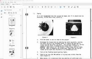
Towing the vehicle 3-48
Safety instructions 3-48
Towing 3-48
Handling the vehicle with a crane 3-49
Safety instructions 3-49
Crane handling 3-49
Loading and transporting the vehicle 3-50
Safety instructions 3-50
Loading the vehicle 3-50
Lashing down the vehicle 3-51
Working with the vehicle 3-52
General safety instructions 3-52
Load diagram 3-52
Control valve of the loader unit: overview 3-53
Control lever for hydraulics of lift and tilt ram of loader unit 3-53
Tip switch on control lever 3-53
Control lever for implements and 3rd control circuit 3-54
Securing control levers for driving on public roads 3-55
3rd electrically operated control
circuit (option) 3-56
Lowering the loader unit with the engine switched off 3-57
Depressurising the quick couplers on the loader unit 3-57
Connecting pressurised quick couplers 3-58
Re-equipping the loader unit 3-60
Fitting implements onto the quickhitch facility 3-60
Taking an implement off the quickhitch facility 3-63
Connection of electrically operated implements (option) 3-64
Operation of the restrictor unit on the tilt ram (option) 3-66
Safety equipment “Hose burst valve” (option) 3-67
Working with standard bucket and pallet forks 3-69
Implements 3-69
Standard bucket 3-69
Working with pallet forks 3-75
I-4 BA 302 01 US-Gehl – Edition 1 0 * 30201busg10IVZ fm
Table of contents
Troubleshooting
Troubleshooting 4-1
Engine trouble 4-2
Maintenance
Maintenance 5-1
Introduction 5-1
Fuel system 5-1
Specific safety instructions 5-1
Refuelling 5-2
Stationary fuel pumps 5-2
Specification for diesel fuel 5-3
Cleaning the fuel tank 5-3
Changing the fuel filter 5-4
Cleaning the screen filter of the fuel pump 5-5
Changing the leak oil line 5-6
Engine lubrication system 5-7
Checking the oil level 5-7
Filling in engine oil 5-8
Changing the engine oil 5-9
Changing the engine oil filter cartridge 5-10
Engine and hydraulics cooling system 5-11
Specific safety instructions 5-11
Engine oil cooler 5-11
Cleaning 5-11
Hydraulic oil cooler 5-12
Cleaning 5-12
Air filter 5-13
Functional check of the dust valve 5-14
Replacing the filter cartridge 5-15
V-belt 5-16
Checking the V-belt tension 5-16
Retightening the V-belt 5-16
Hydraulic system 5-17
Specific safety instructions 5-17
Hydraulic oil level 5-18
Checking the oil level 5-18
Topping up hydraulic oil 5-18
Changing the hydraulic oil 5-19
Important information for the use of biodegradable oil 5-21
Hydraulic oil reflux filter 5-22
Changing the filter insert 5-22
Changing the breather filter 5-23
Hydraulic pressure lines 5-24
Specific safety instructions 5-24
Gearboxes and axles 5-25
Rear axle gearbox 5-26
Checking/topping up the oil level in the rear axle gearbox 5-26
Changing the gearbox oil 5-27
Rear axle differential 5-28
Checking/topping up the oil level in the rear axle gearbox 5-28
Changing the oil 5-28
Front axle differential 5-29
Checking/topping up the oil level 5-29
Changing oil 5-29
Front and rear axle planetary drives 5-30
BA 302 01 US-Gehl – Edition 1 0 * 30201busg10IVZ fm I-5
Table of contents
Checking/topping up the oil level 5-30
Changing the oil 5-30
Lubricating planetary drive bearings 5-31
Lubricating the rear axle oscillation-type bearing 5-31
Loader unit 5-32
Lubricating the pivots on the loader unit 5-32
Tyre care 5-33
Inspection work 5-33
Daily checks 5-33
Checks every week 5-33
Wheel change 5-34
Removing the wheels 5-34
Fitting the wheels 5-34
Heating 5-35
Cleaning the dust filter of the heating system 5-35
Electrical system 5-36
Specific safety instructions 5-36
Service and maintenance work at regular intervals 5-37
Instructions concerning specific components 5-37
Cables, bulbs and fuses 5-37
Alternator 5-37
Battery 5-38
General maintenance work 5-39
Cleaning 5-39
General instructions for all areas of the vehicle 5-39
Inside of operator compartment 5-40
Exterior of the vehicle 5-40
Engine compartment 5-40
Screw connections 5-41
Pivots and hinges 5-41
Engine fluids and lubricants 5-42
Service kits 5-43
Proofs of maintenance 5-44
Proofs of maintenance 5-44
Maintenance plan (overview) 5-48
Maintenance label 5-52
valid for model 521 5-52
Helpful information for using the spare parts list
Helpful information for using the spare parts list 6-1
Introduction 6-1
Composition of spare parts list 6-1
Groups 6-1
Group overview 6-2
Figures 6-3
Number index 6-3
Symbols and abbreviations 6-4
Description of symbols 6-4
Abbreviations 6-6
Indication of position 6-6
Use 6-6
Language codes 6-6
Colour codes 6-7
Vehicle data 6-7
Helpful information for ordering spare parts 6-7
Order information 6-8
Address for your spare part order 6-8
I-6 BA 302 01 US-Gehl – Edition 1 0 * 30201busg10IVZ fm
Table of contents
Specifications
Specifications 7-1
Frame 7-1
Engine 7-1
Power train 7-2
Axles 7-3
Brakes 7-3
Steering 7-4
Work hydraulics 7-4
Pilot control 7-4
Loader unit 7-5
Weights 7-5
Electrical system 7-6
Noise levels 7-9
Vibration 7-9
Tyres 7-10
Dimensions 7-11
Coolant compound table 7-11
Tightening torques 7-12
General tightening torques 7-12
Specific tightening torques 7-12
Annex
Hydraulics diagram (options) A-1
Hydraulics diagram A-2
valid for model 521 A-2
Legend – wiring diagram A-4
Wiring diagram A-7
Wiring diagram legend – options A-8
Wiring diagram – option A-8
More products