$34
Gehl Z35 GEN2 Compacat Excavator Parts Manual 50940278 – PDF DOWNLOAD
Gehl Z35 GEN2 Compacat Excavator Parts Manual 50940278 – PDF DOWNLOAD
FILE DETAILS:
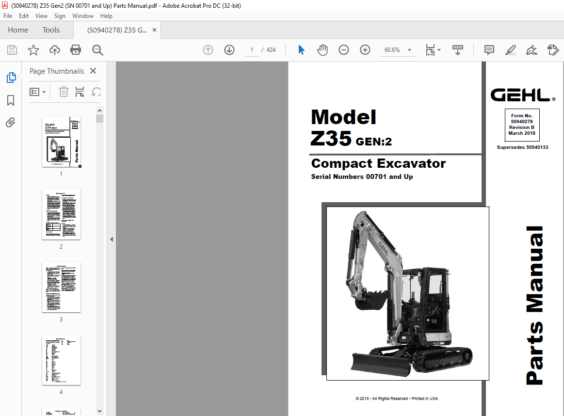
Gehl Z35 GEN2 Compacat Excavator Parts Manual 50940278 – PDF DOWNLOAD
Language : English
Pages : 424
Downloadable : Yes
File Type : PDF
Size: 28.4 MB
TABLE OF CONTENTS:
Gehl Z35 GEN2 Compacat Excavator Parts Manual 50940278 – PDF DOWNLOAD
Introduction i
Table of Contents I
Compact Excavator 1
Special Tools, Paint 1
Gaskets, Belts, Filters Quick-Reference 2
Figure Index (1) – Main Parts 4
Figure Index (2) – Hydraulic Section 5
Label & Accessory 6
Fig 1 – Label (Exterior) 6
Label & Accessory 8
Fig 198 (1A) – Label (Exterior) (Angle
Blade Spec ) 8
Fig 3 – Label (Bonnet Inside) 10
Fig 4 – Label (Canopy) (Standard Blade)
12
Fig 165 (4A) – Label (Canopy) (Angle
Blade Spec ) 14
Fig 6 – Label (Cabin) (Standard
Blade) 16
Fig 167 (6A) – Label (Cabin) (Angle Blade
Spec ) 18
Fig 8 – Label (Quick Coupler) 20
Fig 9 – Case (Tool) 22
Engine Related 24
Fig 10 – Muffler 24
Fig 11 – Air Cleaner 26
Fig 12 – Accelerator 28
Fig 13 – Engine Mount 30
Fig 14 – Radiator Shroud 32
Fig 15 – Radiator & Oil-Cooler 34
Fig 16 – Duct 36
Fig 17 – Fuel Tank 38
Fig 18 – Fuel Line 40
Electrical Parts 42
Fig 19 – Battery 42
Fig 20 – Around Engine (SN before
M00806) 44
Fig 197 (20A) – Around Engine (SN
M00806 and later) 46
Fig 21 – Horn 48
Fig 22 – Seat Mount 50
Fig 23 – Guide Harness 52
Fig 24 – Starter 54
Fig 25 – Auto Deceleration (A/D) 56
Fig 26 – Travel Buzzer 58
Fig 27 – Quick Coupler:Switch Box 60
Fig 28 – Canopy Lamp 62
Fig 29 – Work Lamp 64
Fig 30 – Instrument Panel 66
Fig 31 – ESS (with A/C only) (Standard
Blade Spec ) 68
Fig 169 (31A) – P T O (Angle Blade
Spec ) 70
Fig 170 (31B) – Angle Blade Lever (w/o
AC only) (Angle Blade Spec ) 72
Fig 171 (31C) – Angle Blade Lever & ESS
(w/ AC only) (Angle Blade & ESS
Spec ) 74
Fig 32 – Heater 76
Fig 33 – Control Bracket (Cabin) 78
Air Conditioner & Heater 80
Fig 34 – Air Conditioner (Electric) 80
Fig 35 – Air Conditioner (Unit) 82
Fig 159 (35A) (Air Conditioner) (Unit
Inner Parts) 84
Fig 36 – Air Conditioner (Piping) 86
Fig 37 – Air Conditioner (Engine
Related) 88
Fig 38 – Air conditioner (Condenser) 90
Fig 39 – Heater (Unit) 92
Fig 160 (39A) – Heater (Unit Inner Parts)
94
Fig 40 – Heater (Piping) 96
Fig 41 – Duct (A/C, Heater) 98
Traveling 100
Fig 42 – Sprocket 100
Fig 43 – Idler & Adjust 102
Fig 44 – Track Roller (Y Spec – Before
May 2014) 104
Fig 164 (44A) – Track Roller (K Spec –
May 2014 and later) 106
Fig 45 – Carrier Roller 108
Fig 46 – Crawler 110
Control Equipment 112
Fig 47 – Mount (Valve) 112
Fig 48 – Travel Lever 114
Fig 206 (48A) – Travel Pedals (Folding
Type) 116
Fig 49 – Swing Pedal 118
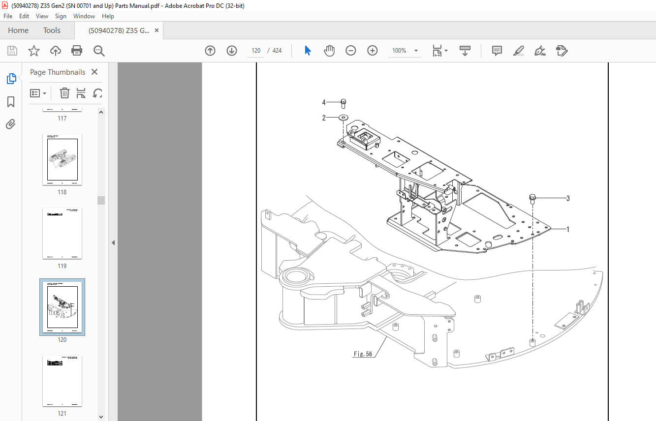
Fig 50 – Pedal Cover 120
Fig 51 – Blade Lever (Standard
Blade) 122
Fig 172 (51A) – Blade Lever (Angle Blade
Spec ) 124
50940278/BP0318 II Printed in U S A
TABLE OF CONTENTS
Fig 52 – Arm Rest 126
Fig 53 – Lock Lever & Stand 128
Frame 130
Fig 54 – Track Frame 130
Fig 55 – Counterweight 132
Fig 163 (55A) – Additional Weight 134
Fig 56 – Turning Frame 136
Fig 57 – Turning Bearing 138
Cover 140
Fig 58 – Cover (Multi) 140
Fig 60 – Cover (Upper) 142
Fig 61 – Cover (Turning Frame) 144
Fig 62 – Cover (Track Frame) 146
Fig 63 – Guard (Frame) 148
Fig 64 – Cover (Frame Front) 150
Around Seat 152
Fig 65 – Step (Cabin) 152
Fig 66 – Step (Canopy) 154
Fig 67 – Cover (Lever) 156
Fig 68 – Cover (Monitor, w/
Canopy) 158
Fig 69 – Cover (Monitor, w/Cabin) 160
Fig 70 – Seat Mount 162
Fig 71 – Seat Mount (Cover) 164
Fig 72 – Seat 166
Fig 73 – Seat (Inner Parts) 168
Fig 74 – Handrail (w/Canopy) 170
Bonnet 172
Fig 75 – Bonnet (Rear) 172
Fig 77 – Bonnet (Front) 174
Fig 78 – Bonnet (Left) 176
Fig 80 – Bonnet (Right) 178
Canopy 180
Fig 82 – Canopy 180
Canopy / Cabin 182
Fig 83 – Mount 182
Cabin 184
Fig 84 – Window Washer 184
Fig 85 – Cabin (Body) 186
Fig 86 – Cabin (Door:1) 188
Fig 87 – Cabin (Door:2) 190
Fig 88 – Cabin (Front Window:1) 192
Fig 89 – Cabin (Front Window:2) 194
Fig 90 – Cabin (Glass) 196
Fig 91 – Cabin (Rear Cover) 198
Fig 92 – Cabin (Electric Parts) 200
Fig 93 – Cabin (Accessory Parts) 202
Fig 94 – Rearview Mirror 204
Fig 95 – Mount (Cabin) 206
Fig 96 – Box (Cabin Heater Spec ) 208
Hydraulic Oil Equipment 210
Fig 97 – Hyd Oil Pump Mount 210
Fig 98 – Hyd Oil Pump 212
Fig 99 – Hyd Oil Pump (ESS Spec ) (with
A/C only) 214
Fig 100 – Boom Cylinder (Y SPEC )—
Early Machines 216
Fig 200 (100A) – Boom Cylinder (K
SPEC )—Later Machines 218
Fig 101 – Arm Cylinder (Y SPEC )—Early
Machines 220
Fig 201 (101A) – Arm Cylinder (K
SPEC )—Later Machines 222
Fig 102 – Bucket Cylinder (Y Spec )—
Early Machines 224
Fig 202 (102A) – Bucket Cylinder (K
Spec )—Later Machines 226
Fig 103 – Swing Cylinder (Y Spec )—Early
Machines 228
Fig 203 (103A) – Swing Cylinder (K
Spec )—Later Machines 230
Fig 104 – Lift Cylinder (Standard Blade)
(Y Spec )—Early Machines 232
Fig 204 (104A) – Lift Cylinder (Standard
Blade) (K Spec )—Later
Machines 234
Fig 205 (104B) – Lift Cylinder (Angle
Blade Spec ) 236
Fig 173 (104A) – Angle Cylinder (Angle
Blade Spec ) 238
Fig 105 – Travel Motor (Standard
Blade) 240
Fig 174 (105A) – Travel Motor (Angle
Blade Spec ) 242
Fig 106 – Turning Motor 244
Fig 107 – Swivel Joint (Y Spec ) (SN
Before M00730) (Standard Blade) 246
Fig 108 – Swivel Joint (N Spec ) (SN
M00730 & Later) (Standard
Blade) 248
Fig 175 (108A) – Swivel Joint (Angle
Blade Spec ) 250
Fig 109 – Control Valve (1/7) (Standard
Blade) 252
Fig 110 – Control Valve (2/7) (Standard
Blade) 254
Printed in U S A III 50940278/BP0318
TABLE OF CONTENTS
Fig 111 – Control Valve (3/7) (Standard
Blade) 256
Fig 112 – Control Valve (4/7) (Standard
Blade) 258
Fig 113 – Control Valve (5/7) (Standard
Blade) 260
Fig 114 – Control Valve (6/7) (Standard
Blade) 262
Fig 115 – Control Valve (7/7) (Standard
Blade) 264
Fig 176 (115A) – Control Valve (1/8)
(Angle Blade Spec ) 266
Fig 177 (115B) – Control Valve (2/8)
(Angle Blade Spec ) 268
Fig 178 (115C) – Control Valve (3/8)
(Angle Blade Spec ) 270
Fig 179 (115D) – Control Valve (4/8)
(Angle Blade Spec ) 272
Fig 180 (115E) – Control Valve (5/8)
(Angle Blade Spec ) 274
Fig 181 (115F) – Control Valve (6/8)
(Angle Blade Spec ) 276
Fig 182 (115G) – Control Valve (7/8)
(Angle Blade Spec ) 278
Fig 183 (115H) – Control Valve (8/8)
(Angle Blade Spec ) 280
Fig 116 – Joystick Control (Right) 282
Fig 117 – Joystick Control (Left) 284
Fig 118 – 2-Way Valve (Standard
Blade) 286
Fig 184 (118A) – 2-Way Valve (Angle
Blade Spec ) 288
Fig 119 – Solenoid Valve (ESS:PTO) (with
A/C only) 290
Fig 120 – Solenoid Valve (PTO) 292
Fig 185 (120A) – Solenoid Valve (P T O 2)
(Angle Blade Spec ) 294
Fig 186 (120B) – Solenoid Valve Bracket
(P T O 2) (Angle Blade Spec ) 296
Fig 121 – Hyd Oil Tank 298
Fig 142 – Quick Coupler (Hitch
Cylinder) 300
Hydraulic Oil Piping 302
Fig 122 – Tank-Pump, C/V 302
Fig 123 – C/V-Turning Motor 304
Fig 124 – C/V:Fitting1 (Standard
Blade) 306
Fig 187 (124A) – CV:Fitting1 (Angle
Blade Spec ) 308
Fig 125 – C/V:Fitting 2 (Standard
Blade) 310
Fig 188 (125A) – CV:Fitting 2 (Angle
Blade Spec ) 312
Fig 126 – C/V-Return, Drain 314
Fig 127 – C/V-Boom Bulkhead,
Swing 316
Fig 128 – C/V-Boom Cylinder 318
Fig 129 – Hyd Oil Piping (C/V-Swivel
Joint) (Standard Blade) 320
Fig 189 (129A) – Hyd Oil Piping (Control
Valve-Swivel Joint) (Angle Blade
Spec ) 322
Fig 130 – Hyd Oil Piping (Track Frame)
(Standard Blade) 324
Fig 190 (130A) – Hyd Oil Piping (Track
Frame) (Angle Blade Spec ) 326
Fig 131 – Hyd Oil Piping (Arm Cylinder,
Bucket Cylinder) 328
Fig 133 – Hyd Oil Piping (P T O :C/VBoom)
330
Fig 134 – Hyd Oil Piping (P T O :Boom-
Arm End) 332
Fig 136 – Hyd Oil Piping (P T O :Solenoid
Valve) (Standard Blade) 334
Fig 191 (136A) – Hyd Oil Piping
(P T O :Solenoid Valve) (Angle Blade
Spec ) 336
Fig 137 – Hyd Oil Piping (P T O :Solenoid
Valve, ESS) (Standard Blade) (with A/C
only) 338
Fig 192 (137A) – Hyd Oil Piping
(P T O :Solenoid Valve, ESS) (Angle
Blade Spec ) (with A/C only) 340
Fig 193 (137B) – Hyd Oil Piping
(P T O2:Angle Blade) (Angle Blade
Spec ) 342
Fig 138 – Control Piping (1) (Standard
Blade) 344
Fig 194 (138A) – Control Piping (1) (Angle
Blade Spec ) 346
Fig 139 – Control Piping (2) 348
Fig 140 – Accumulator 350
Fig 141 – Greasing 352
Fig 143 – Quick Coupler (Hyd Oil
Piping:1) 354
50940278/BP0318 IV Printed in U S A
TABLE OF CONTENTS
Fig 145 – Quick Coupler (Hyd Oil
Piping:2) 356
Fig 147 – Quick Coupler (Body) 358
Implement 358
Fig 149 – Boom Bracket 360
Fig 151 – Boom 362
Fig 153 – Arm 364
Fig 155 – Bucket Arm & Link 366
Fig 157 – Blade (Standard) 368
Fig 195 (157A) – Blade (Angle Blade
Spec ) 370
Fig 161 – Radio Kit (option) 372
Hydraulic Quick-Connect Couplers 374
DESCRIPTION:
Gehl Z35 GEN2 Compacat Excavator Parts Manual 50940278 – PDF DOWNLOAD
Serial Numbers 00701 and Up
General:
•MANITOU AMERICAS, INC. reserves the right to make changes or improvements in the design or construction of any part of the machine without incurring the obligation to install such changes on any previously delivered machines.• This parts manual should not be used as a technical data reference; it uses simplified illustrations and does not detail servicing procedures.
Parts Ordering Information:
• When ordering service parts, specify the correct part number, full description and quantity required, as well as the machine and engine model and serial numbers. For your safety and continued proper operation, use only genuine GEHL service parts.• “Right”, “left”, “front” and “back” are determined from a position sitting on the operator’s seat and facing forward, and the excavator “house” rotated so that the blade is also facing forward.
Torque Charts:
Standard attaching hardware torque values are provided on the inside back cover, and some torque values may be shown in illustrations. Metric torque values are shown in Newton-meters, and are converted to foot-pounds by multiplying by 0.738.
Illustrations and Parts Lists:
• Not all parts shown in the illustrations may be included in the parts listings; some are not serviced separately or are not included on engines sold in all areas.• Ref. Nos. shown in the parts listings without part numbers are shown for reference purposes only and are not available for purchase.• Boxes or brackets may be used in some illustrations to indicate assemblies (part groupings), or in some cases to highlight different versions of individual parts or assemblies.• Text references may be present on some illustrations to provide additional information.• Some illustrations will contain circled letters or a circled combination of letters and numbers in addition to the regular number callouts. These special callouts may be used to identify hydraulic port locations which are marked on components, or to identify the two ends of a hose, tube, or other part that is shown split in the illustration. They may also be used to indicate a common reference point when different versions of components are shown on the illustration.
IMAGES PREVIEW OF THE MANUAL:
More products