$36
Gleaner EU 9255 DynaFlex Draper Header Service Manual 79036985A – PDF DOWNLOAD
Gleaner EU 9255 DynaFlex Draper Header Service Manual 79036985A – PDF DOWNLOAD
FILE DETAILS:
Gleaner EU 9255 DynaFlex Draper Header Service Manual 79036985A – PDF DOWNLOAD
Language : English
Pages : 629
Downloadable : Yes
File Type : PDF
Size: 145 MB
TABLE OF CONTENTS:
Gleaner EU 9255 DynaFlex Draper Header Service Manual 79036985A – PDF DOWNLOAD
GENERAL INFORMATION
Gleaner®
9255
DynaFlex Draper Header
SERVICE MANUAL
79036985A
02 – General Information
Contents
Contents
Introduction 02-1
Units of Measurement 02-1
Replacement Parts 02-1
Machine Identification 02-1
Machine Usage 02-2
Operation 02-3
Checklists 02-3
Variable Speed Drive Lockout 02-4
Feeder Chain Speed 02-4
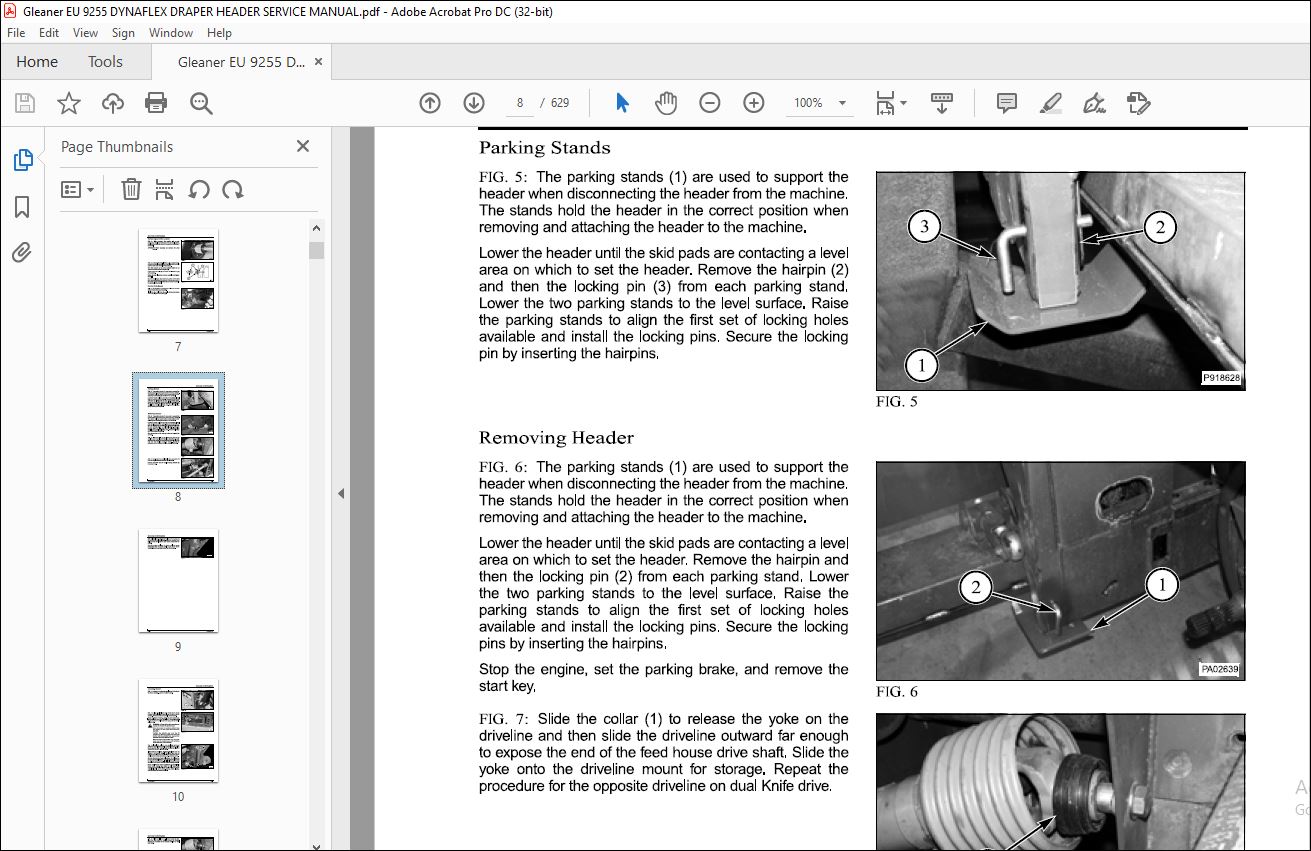
Parking Stands 02-5
Removing Header 02-5
Attaching Header 02-7
Extremity Lights 02-10
Header Break-In 02-11
Draper Care 02-11
Unplugging the Header 02-11
Reel Speed 02-12
Draper Speed 02-12
Tine Replacement 02-12
Completing Packages 02-13
Sickle Storage 02-15
Flighting Fillers 02-15
Cutterbar Float Lockout 02-15
Reel Divider 02-16
Divider Rod 02-17
Adjustments 02-18
Reel Lift Cylinder Synchronization 02-18
Reel Height (Leveling) 02-19
Reel Position 02-20
Reel Motor Chain 02-21
Recommended Cutterbar Flex Pressure 02-22
Adjusting Cutterbar Flex Pressure 02-22
Cutterbar Flex System – Bleeding Air 02-24
Tine Pitch Adjustment 02-25
Header (Cutterbar) Tilt Adjustment 02-25
Auger Adjustment 02-27
Header Height Control 02-28
Draper Tension (Side) 02-32
Draper Tension (Center) 02-33
Counter Balance Spring – Center Deck 02-33
Side Draper Drive Belt 02-34
Center Draper Drive Belt 02-36
79036985A 02-i
Contents
Auger Drive Belt 02-37
Reel Speed Sensor Adjustment 02-39
Sickle Timing – Dual Knife Drive 02-39
Lubrication and Maintenance 02-41
General Information 02-41
Lube Decal 02-48
Lubrication Chart 02-49
Lubrication Details 02-49
Reel Drive Chain 02-55
Troubleshooting 02-56
Cutterbar 02-56
Reel 02-61
Draper 02-62
Auger 02-62
Specifications 02-64
Dimensions and Weights 02-64
Pick-Up Reel 02-65
Reel Drive 02-66
Reel Height Control 02-66
Cutterbar 02-66
Sickle 02-66
Header Tilt 02-67
Drapers 02-67
Center Conveyor 02-67
General Lubrication 02-67
Tire Pressure 02-68
Wheels 02-68
Header Transport 02-68
Special tools 02-69
INDEX 02-71
02-ii 79036985A
DRIVES
Gleaner®
9255
DynaFlex Draper Header
SERVICE MANUAL
79036985A
03 – Drives
Contents
Contents
Side Draper Drive Belt 03-1
Removal 03-1
Installation 03-3
Center Draper Drive Belt 03-5
Removal 03-5
Installation 03-7
Auger Drive Belt 03-8
Removal 03-8
Installation 03-9
Draper (Main) Drive {Left and Right} 03-11
Removal 03-11
Disassembly 03-18
Assembly 03-20
Installation 03-23
Draper Drive {Left and Right) 03-29
Removal 03-29
Installation 03-35
Auger Drive 03-43
Removal 03-43
Installation 03-47
Torque Limiter (Auger) 03-52
Center Draper Drive Shaft 03-55
Removal 03-55
Clutch {Torque Limiter) – Center Draper 03-59
Installation 03-63
Center Draper Drive Gearcase 03-67
Removal 03-67
Installation 03-70
Components (Gearcase) 03-74
Disassembly 03-76
Inspection 03-78
Assembly 03-79
Sickle (Right Angle) Drive Box 03-87
Removal 03-87
Installation 03-90
Components (Gearbox) 03-92
Special Tools 03-94
Disassembly 03-95
Inspection 03-98
Assembly 03-99
Sickle Drive Gearbox 03-103
Removal 03-103
79036985A 03-i
Contents
Installation 03-105
Components (Gearbox) 03-110
Disassembly and Assembly 03-112
Power Take Off Drive Shafts 03-131
Disassembly 03-131
Inspection 03-136
Assembly 03-136
U-Joint Drive Shaft Assembly- Sickle 03-143
Components 03-143
Removal 03-144
Inspection 03-147
Installation 03-148
U-Joint Replacement 03-150
INDEX 03-157
04 – Cutting Components
Contents
Contents
Sickle Replacement 04-1
Removal 04-1
Inspection 04-6
Installation 04-8
Sickle (Standard) Hold Down Pressure 04-17
Sickle Register 04-17
Sickle Timing – Dual Knife Drive 04-18
Sickle Section Replacement 04-19
Standard Sickle Sections 04-19
SCH Sickle Sections 04-27
Guards, Wear Plates, SCH Knife Back Rollers, and Hold-Downs 04-36
Standard Sickle 04-38
SCH Sickle 04-43
Removal 04-43
Installation 04-44
INDEX 04-49
05 – Electrical
Contents
Contents
Introduction 05-1
Basic Troubleshooting Procedures 05-1
Basic Checks 05-2
Tools 05-3
Multimeter 05-4
Sensor Tester 05-5
General Testing Procedures 05-6
Visual Inspection 05-6
Continuity Check 05-6
Voltage Check 05-6
Testing For Open Circuits 05-7
Testing For Short Circuits 05-7
Testing For High Resistance 05-7
Wiring Diagram 05-8
Wiring Diagram Color Code 05-8
Feeder Harness Connector Numbers 05-9
Wiring Diagram 05-10
Splice Reference Chart 05-13
Electrical Schematic 05-15
Electrical Schematic Legand 05-16
Electrical Components 05-18
Location 05-18
Adjustments 05-20
Testing 05-21
Solenoid Tests 05-27
Visual Test 05-27
Voltage Test 05-27
Coil Test 05-27
Lighting Tests 05-28
INDEX 05-29
06 – Hydraulics
Contents
Contents
General Information 06-1
Header HyDraulic Schematic 06-3
Reel Lift Hydraulic Schematic 06-5
Cutterbar Float Hydraulic Schematic 06-7
Reel Drive Hydraulic Schematic 06-9
Header Interface Hydraulic Tilt Schematic 06-11
FloaUReel Valve Assembly 06-13
Operating Modes 06-14
O-ring and Backup Rings 06-14
Removal 06-15
Disassembly 06-18
Inspection 06-19
Assembly 06-21
Installation 06-22
Troubleshooting 06-25
Accumulator 06-29
Removal 06-29
Installation 06-32
Special Tools 06-35
Check Charge Pressure 06-35
Discharging 06-35
Charging 06-36
Float Cylinders 06-36
Removal 06-36
Installation 06-40
Float Cylinder – Middle Inner Tilt Arm 06-42
Float Cylinder – Outer Tilt Arm 06-44
Reel Relief Valve 06-45
Removal 06-45
Disassembly 06-46
Assembly 06-46
Installation 06-46
Adjusting the reel relief valve 06-47
Reel Motor 06-48
Disassembly 06-48
Assembly 06-51
Timing Procedure 06-55
Reel Lift Cylinders 06-57
Reel Lift Master Cylinder 06-57
Reel Lift Slave Cylinder 06-60
Header Interface Tilt Cylinder 06-62
Disassembly 06-62
79036985A 06-i
Contents
Inspection 06-63
Assembly 06-64
INDEX 06-65
07 – Housing and Shields
Contents
Contents
Hydraulic Interface Group 07-1
Removal 07-2
Installation 07-4
Tilt Cylinder 07-7
Center Deck Group 07-12
Center Draper (Belt) 07-14
Center Deck 07-18
Disassembly 07-28
Assembly 07-37
Side Canvas and Roller Group 07-51
Side Draper (Belt) 07-53
Drive Roller 07-60
Idler Roller 07-83
Feather Sheet Groups 07-89
Feather Sheets 07-91
Belt Guides 07-93
Belt Supports – Rear 07-96
Skid Plate and Cutterbar Group 07-100
Plastic Skid Replacement 07-103
Removal 07-103
Installation 07-108
Tilt Arm Group 07-114
Removal 07-117
Installation 07-135
Auger Group 07-157
Removal 07-158
Disassembly 07-161
Assembly 07-162
Installation 07-163
Shields Group 07-166
Divider Shield 07-166
End Shield 07-175
Drives Shield 07-180
End Panels Group 07-183
Removal 07-183
Installation 07-186
08 – Reel
Contents
Contents
Reel 08-1
Removal 08-1
Inspection 08-4
Installation 08-6
Removing the tine tube 08-9
Tine Replacement 08-9
Installing the tine tube 08-10
Troubleshooting 08-11
Reel Carrier Assembly 08-12
Left 08-12
Right 08-14
Reel Support Arm 08-19
Removal 08-19
Installation 08-21
Reel Actuator 08-24
Removal 08-24
Assembly and Installation 08-25
Reel Lift Cylinders 08-27
Synchronizing Lift Cylinders 08-27
Removal 08-30
Installation 08-32
Single Point Mobile Connector (Header) 08-34
Reel Drive (Hydraulic) 08-35
Reel Speed Pickup 08-37
Motor 08-41
INDEX 08-47
DESCRIPTION:
Gleaner EU 9255 DynaFlex Draper Header Service Manual 79036985A – PDF DOWNLOAD
GENERAL INFORMATION:
INTRODUCTION:
The information contained in this manual covers service information for the DynaFlex™ Header. The header operator’s manual as well as the machine operator’s manual must be kept at hand for reference at all times.
Units of Measurement:
Measurements are given in metric units followed by the equivalent in U.S. units. Hardware sizes are given in
millimeters for metric hardware and inches for U.S. hardware.
Replacement Parts:
To receive efficient service, always give the following information:
• Correct part description or part number.
• Model number of the machine.
• Serial number of the machine.
IMAGES PREVIEW OF THE MANUAL:
More products