$34
Gleaner NA Harvesting 7000 & 8000 Grain Header Service Manual – PDF DOWNLOAD
Gleaner NA Harvesting 7000 & 8000 Grain Header Service Manual – PDF DOWNLOAD
FILE DETAILS:
Gleaner NA Harvesting 7000 & 8000 Grain Header Service Manual – PDF DOWNLOAD
Language : English
Pages : 498
Downloadable : Yes
File Type : PDF
Size: 204 MB
IMAGES PREVIEW OF THE MANUAL:
DESCRIPTION:
Gleaner NA Harvesting 7000 & 8000 Grain Header Service Manual – PDF DOWNLOAD
GENERAL INFORMATION:
• READ the Operator’s Manuals carefully to acquaint yourself with the header and combine. Operating unfamiliar equipment can cause accidents.• ALWAYS shift transmission to neutral, stop engine, set brake and remove start key before leaving the operator’s station, or before permitting anyone to inspect, clean, lubricate, adjust or repair any part of the combine or its attachments, unless otherwise specifically recommended in the Service Manual or Operator’s Manual.• NEVER permit anyone to work under the header or feeder housing or between the header and combine UNLESS the lift ram stop is fully engaged on the lift ram, the engine is stopped, the brake is set, the key is removed from the start switch, and the header is latched securely to the feeder housing.• NEVER permit the operator or another person to engage or disengage the lift ram stop UNLESS the combine engine is stopped, the brake is set, and the key is removed from the start switch while that person is between the header and the combine or under the feeder housing to move the lift ram stop.• NEVER permit anyone to get under the reel UNLESS BOTH RIGHT HAND and LEFT HAND reel lift ram stops are fully engaged over the lift ram rods and against the ends of the lift ram barrels, the combine engine is stopped, the brake is set and the start key is removed.• BE SURE that everyone is clear of the combine before starting the engine and mechanism or its attachments.• ALWAYS be sure that all shields, guards and access doors are in place when header is in operation.• DO NOT try to clean, adjust, or service the header while the header or combine is running.• KEEP all belts and chains in alignment and at the proper tension.• NEVER turn the header conveyor or drives unless ALL parts of the body and articles of clothing are well clear of the sickle, chains, gears, and other moving parts.• FOR YOUR SAFETY and the safety of others, SAFETY AND OPERATIONAL DECALS that become damaged, faded, or come off should be replaced immediately.• REMEMBER that safe operation is no accident.• ALWAYS lower the Grain Head to the ground, or block, or lock it up securely before disconnecting or servicing any part of the hydraulic system.• ALWAYS keep the drives, moving parts, and shields clean of chaff and straw buildup to reduce the possibility of fire.• Before attaching, adjusting or working on the drive line, disengage the header drive, lower header to the ground, stop engine, remove starter key and set the parking brake.• Before engaging the header drive, carefully drive and lower the header to check the clearance, drive line shaft slide range, and articulation.• Ensure that all drive lines have the correct guards and they are in good operating condition.• Never use the drive line as a step.• Never wear loose fitting clothing and keep at least your height in distance away from a rotating drive line.
TABLE OF CONTENTS:
Gleaner NA Harvesting 7000 & 8000 Grain Header Service Manual – PDF DOWNLOAD
GENERAL INFORMATION 1-3
Safety 1-3
Signal Words 1-4
Road and Highway Operation 1-6
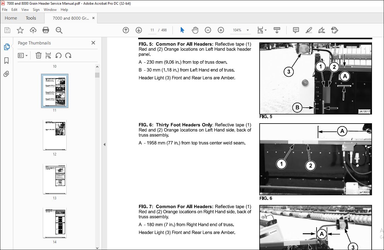
Safety Lights and Reflectors 1-6
Safety Signs 1-9
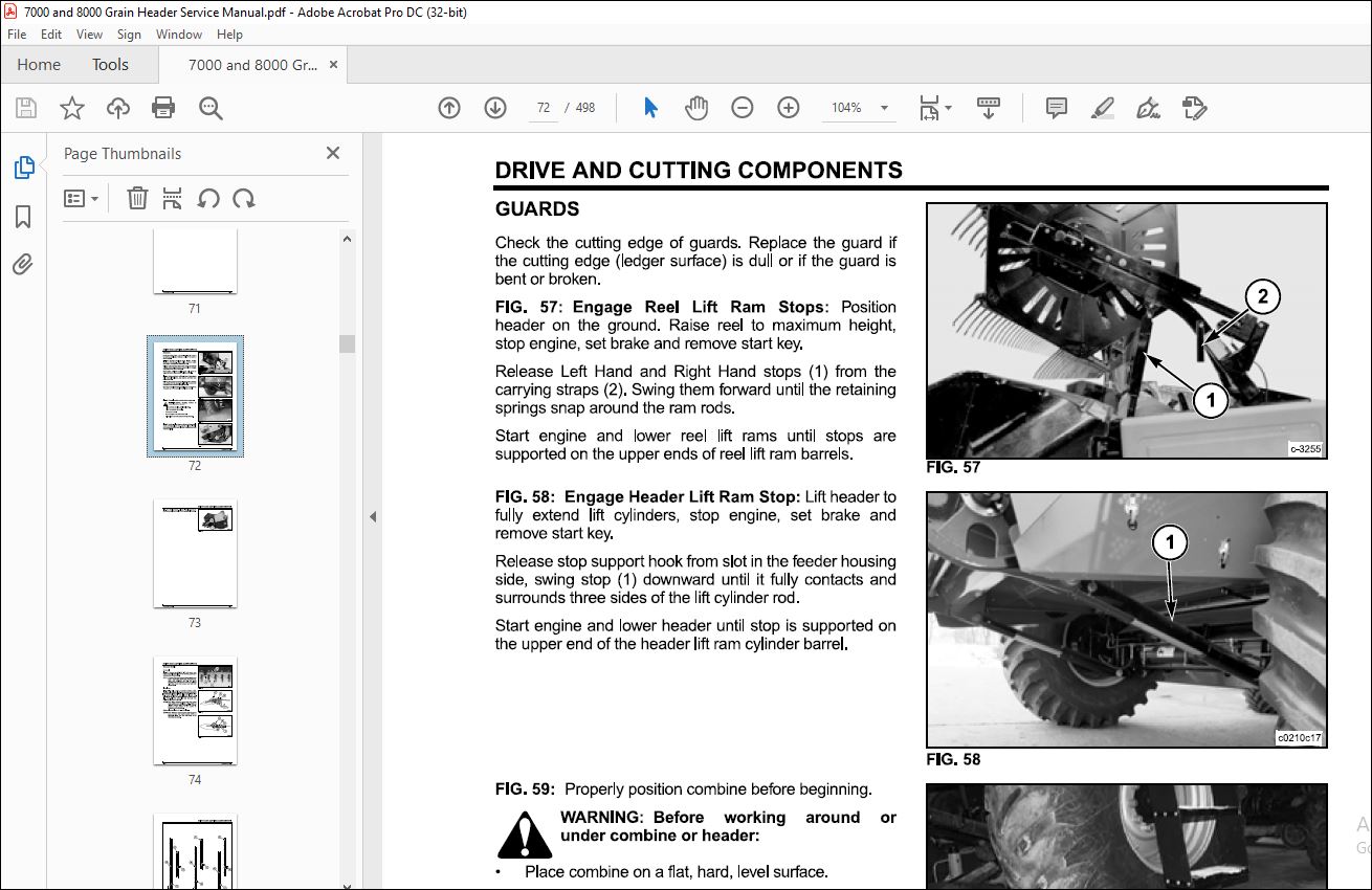
Header Lift Cylinder Stop 1-11
Reel Lift Ram Stops 1-12
Shields 1-13
Header Transport Tie-Down 1-16
Installing Header on Combine 1-20
Leveling Header 1-24
Header Identification 1-24
Metric Information 1-26
Header Specifications 1-27
HEADER SPEED CHART AT RATED ENGINE SPEED 1-31
Combine with Standard Header Drive 1-31
Combine with Variable Speed Header Drive 1-31
Lubrication and Maintenance 1-32
Service 1-35
Special Tools 1-37
SICKLE REPLACEMENT 2-3
Removal – Sickle Drive Pin and Sickle 2-5
Inspection 2-7
Sickle Head Bearing Housing Assembly 2-11
Installation – Sickle and Sickle Drive Pin 2-13
SICKLE REGISTER 2-15
SICKLE SECTION REPLACEMENT 2-18
Standard Sickle 2-19
Clean Cut Sickle 2-22
4 pt Australian Sickle 2-24
SCH Sickle 2-26
GUARDS 2-30
Standard Sickle 2-32
Clean Cut Sickle 2-36
4 pt Australian Sickle 2-40
“SCH” Sickle 2-45
Wear Plates and Hold-down Clips 2-49
Standard Sickle 2-51
Clean Cut Sickle 2-55
4 pt Australian Sickle 2-59
“SCH” Sickle 2-63
CUTTERBAR ANGLE (RIGID HEADER) 2-68
Removal 2-68
Installation 2-69
FEATHER SHEETS (RAISED) 2-70
Maintenance and Operation 2-70
FEATHERED SHEETS (NON-RAISER) 2-74
Removal 2-75
Installation 2-76
CUTTERBAR (FLEX HEADER) 2-77
Removal 2-77
Installation 2-79
FRONT AND REAR FLEX HEAD FILLER PANELS (PAN END) 2-82
Removal 2-83
Installation 2-84
SKID PLATES (FLEX HEADER) 2-86
Removal 2-87
Plastic Skid Plates 2-96
Installation 2-97
AUTOMATIC HEADER HEIGHT CONTROL 2-105
General Information 2-105
Removal (Linkage) 2-106
Installation (Linkage) 2-108
Adjustment (Linkage) 2-110
LOWER STABILIZER ASSEMBLY (FLEX HEADER) 2-112
Removal 2-113
Installation 2-117
UPPER STABILIZER ASSEMBLY (FLEX HEADER) 2-121
Removal 2-121
Installation 2-122
CUTTERBAR GROUND PRESSURE SPRINGS (FLEX HEADER) 2-124
Removal 2-125
Installation 2-127
Adjustment 2-128
STABILIZER ASSEMBLY 2-130
Removal 2-131
Installation 2-133
CUTTERBAR TILT ARM (RIGID HEADER) 2-136
Removal 2-137
79022920 A Rev 2-1
DRIVE AND CUTTING COMPONENTS
Installation 2-140
Tilt Adjustment 2-144
CUTTERBAR TILT ARM AND STABILIZERS (FLEX HEADER) 2-146
Removal 2-14 7
Installation 2-151
Tilt Adjustment (Cutter Bar and Cutter Bar Stabilizers) 2-154
HEADER DRIVE 2-156
Removal 2-156
Disassembly 2-160
Inspection 2-164
Assembly 2-164
Installation 2-173
CONVEYOR DRIVE 2-177
Conveyor Drive Chain 2-178
Conveyor Slip Clutch 2-180
WOBBLE BOX DRIVE BELT 2-184
Removal 2-184
Installation and Adjustment 2-187
WOBBLE BOX 2-190
Removal 2-190
Disassembly and Inspection 2-194
Assembly 2-196
Installation 2-209
CONVEYOR 2-214
Conveyor Adjustments 2-214
Conveyor Finger and Guide Replacement 2-217
Conveyor Crankshaft, Finger Retainers, and Bearings 2-220
Right Hand Conveyor Shaft Replacement 2-227
Left Hand Conveyor Shaft Replacement 2-233
Flighting Extensions 2-237
Header Conveyor Replacement 2-240
Conveyor End Plate Replacement 2-244
Conveyor Straighten 2-246
DIVIDERS 2-247
Dividers (Rigid Headers) 2-247
Dividers (Flex Headers) 2-251
Divider Spring Replacement (Flex Header) 2-260
Long Wing Divider Option {Flex Header) 2-264
TROUBLESHOOTING FLEX HEAD VIBRATION PROBLEMS 2-268
Wobble Box Speed 2-268
Loose Parts 2-269
HOUSING 3-3
Header Weights {Transverse Combine) 3-3
Fairing Extension Replacement 3-5
Straw Retarder Wear Extension Replacement 3-12
Seal Strip Replacement {Transverse Header) 3-19
Seal Strip Replacement (Axial Header) 3-22
Rock Guard Replacement (Rigid Header) 3-25
Truss, Header Hanger, and Pan Back Replacement 3-26
Pan Bottom Replacement (Rigid Header) 3-46
Pan Bottom Replacement {Flex Header) 3-53
Left Hand Pan End Replacement 3-60
Right Hand Pan End Replacement 3-82
Lower Frame Replacement {Torque Tube) 3-95
GENERAL INFORMATION 4-3
Safety 4-3
Signal Words 4-4
Reflectors 4-6
Safety Signs 4-7
Header Lift Cylinder Stop 4-8
Reel Lift Ram Stops 4-9
Shields 4-10
Metric Information 4-12
Reel Specifications 4-13
Reel Speed Chart at Rated Engine Speed 4-14
Lubrication and Maintenance 4-15
Service 4-17
REEL HEIGHT ADJUSTMENT 4-19
BAT REEL 4-20
Removal 4-20
Inspection and Repair 4-22
Assembly and Installation 4-23
PICKUP REEL (HCC) 6 BAT “LEVEL 2” 4-29
Maintenance 4-29
Tine Pitch Adjustment 4-32
Removal 4-32
Inspection and Repair 4-34
Assembly and Installation 4-35
PICKUP REEL (UHC U-11) 6 BAT 4-45
General Information 4-45
Maintenance 4-45
Inspection and Repair 4-46
Removal 4-4 7
Inspection and Repair 4-50
Assembly and Installation 4-51
REEL ARM 4-60
Removal 4-60
Assembly 4-62
POWER (ELECTRIC) REEL ADJUSTMENT 4-65
Electrical Adjusting Motors 4-65
Specifications 4-66
Removal 4-68
Assembly 4-69
REEL DRIVE (HYDRAULIC) 4-71
Reel Speed 4-71
Reel Speed Control Valve 4-71
Torque Limiter (Adjustable Relief Valve) 4-72
Reel Motor and Chain 4-73
REEL LIFT CYLINDERS 4-85
More products