$36
Gleaner NA Harvesting 7200 Rigid 8200 Flex Grain Header Service Manual – PDF DOWNLOAD
Gleaner NA Harvesting 7200 Rigid 8200 Flex Grain Header Service Manual – PDF DOWNLOAD
FILE DETAILS:
Gleaner NA Harvesting 7200 Rigid 8200 Flex Grain Header Service Manual – PDF DOWNLOAD
Language : English
Pages : 660
Downloadable : Yes
File Type : PDF
Size: 114 MB
IMAGES PREVIEW OF THE MANUAL:
DESCRIPTION:
Gleaner NA Harvesting 7200 Rigid 8200 Flex Grain Header Service Manual – PDF DOWNLOAD
A WORD TO THE OPERATOR:
- Read and understand the Operator Manual and the manual for all attachments before operating the machine. Learn how to operate the machine and how to use the controls properly.
- Do not let anyone operate the machine without instruction and training. For your personal safety and the personal safety of others, follow all safety precautions and instructions found in the manuals and on decals affixed to the machine and attachments.
• READ the Operator Manuals carefully to acquaint you with the header and the machine. Operating unfamiliar equipment can cause accidents.• ALWAYS shift the transmission to neutral, stop the engine, set the brake and remove the start key before leaving the operators station, or before permitting anyone to inspect, clean, lubricate, adjust or repair any part of the machine or its attachments, unless otherwise specifically recommended in the Service Manual or the Operators Manual.• NEVER permit anyone to work under the header or the feeder housing or between the header and the machine UNLESS the lift ram stop is fully engaged on the left lift ram, the engine is stopped, the brake is set, the key is removed from the start switch and the header is latched securely to the feeder housing.• NEVER permit the operator or another person to engage or disengage the lift ram stop UNLESS the engine is stopped, the brake is set, and the key is removed from the start switch while that person is between the header and the machine or under the feeder housing.• NEVER permit anyone to get under the reel UNLESS BOTH THE RIGHT HAND and LEFT HAND reel ram stops are fully engaged over the lift ram rods and against the ends of the lift ram barrels, the engine is stopped, the brake is set, and the start key is removed.• BE SURE that everyone is clear of the machine before starting the engine and mechanism or its attachments.• ALWAYS be sure that all shields, guards and access doors are in place when the header is in operation. • DO NOT try to clean, adjust, or service the header while the header or the machine is running.• KEEP all belts and chains in alignment and at the proper tension.• NEVER turn the header conveyor or drives unless ALL parts of the body and articles of clothing are well clear of the sickle, chains, gears, and other moving parts.• FOR YOUR SAFETY and the safety of others, all SAFETY AND OPERATIONAL DECALS that become damaged, faded, or come off should be replaced immediately.
TABLE OF CONTENTS:
Gleaner NA Harvesting 7200 Rigid 8200 Flex Grain Header Service Manual – PDF DOWNLOAD
Safety 01-3
Safety Alert Symbol 01-3
Signal Words 01-3
Informational Messages 01-3
Safety Signs 01-4
A Word to the Operator 01-4
Fire Prevention and First Aid 01-6
Prepare for Operation 01-6
Road and Highway Operation 01-7
Header Transport Tie-Down 01-8
Operation 01-9
Maintenance 01-12
Engine Safety 01-13
Tire Safety 01-14
Battery Safety 01-14
Cylinder Stops 01-16
Header Lift Cylinder Stop 01-16
Shields 01-18
Introduction 01-21
Replacement Parts 01-21
Recommended Header/Machine Usage 01-21
Machine Identification 01-22
Operation 01-23
Checklists 01-23
Headers – General 01-24
Removing Header 01-24
Attaching Header 01-28
Leveling the Header (Non-lateral Tilt) 01-30
Header Weight, Right-hand End 01-30
Header Extremity Lights 01-31
Reel Position 01-32
Reel Speed Control Valve 01-34
Torque Limiter (Adjustable Relief Valve) 01-35
Reel Lift Arms 01-36
Tine Pitch Adjustment 01-37
Tine Replacement 01-37
Reel Motor Chain Adjustment 01-40
Header Auger Adjustments 01-40
Seal Strip 01-44
Closure Extensions 01-44
Straw Retarders 01-44
Sickle Storage 01-44
Cutterbar Tilt Adjustments 01-45
79032956 A Rev 01-1
Contents
Header Control System 01-50
Dividers 01-51
Auger Drive Chain Tension 01-52
Sickle Drive Gear Box 01-52
Recommended Basic Settings 01-54
Field Service tips 01-56
Lubrication and Maintenance 01-64
Drive Belts and Chains 01-64
Installation of Relubeable Bearings 01-66
Metric Information 01-67
Lubrication Details 01-68
Specifications 01-71
Rigid Headers 01-71
Flexible Cutterbar Headers 01-71
Pick-up Reel – HCC Model 01-71
Bat Reel metal Bats 01-71
Reel Drive 01-71
Reel Height Control 01-72
Cutterbar 01-72
Knife 01-72
Conveyor 01-72
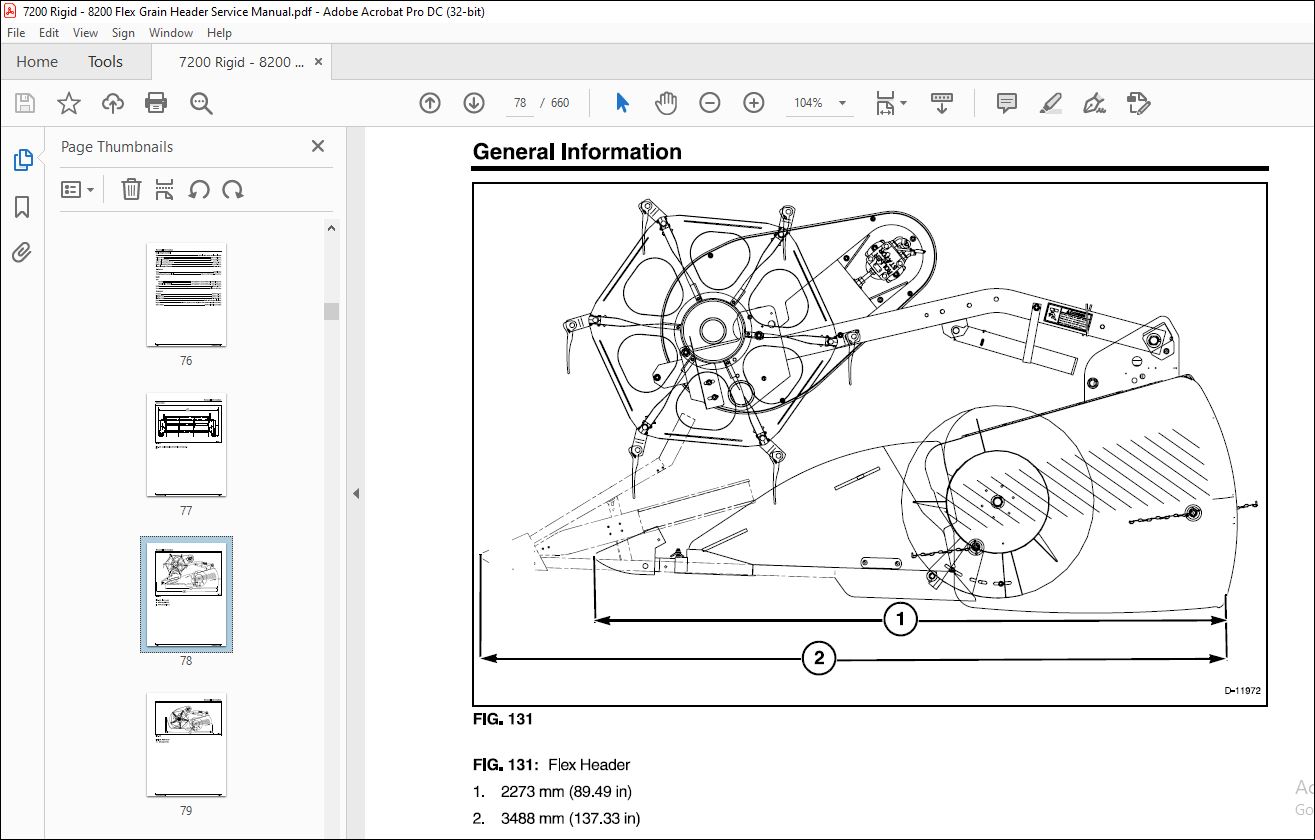
Dimensions 01-73
Header Speed Chart at Rated Engine Speed 01-76
Electric Actuator 01-77
Special Tools 01-78
Sickle Replacement 02-3
Removal 02-5
Inspection 02-7
Installation 02-10
Sickle Register 02-15
Sickle Section Replacement 02-16
Standard, Standard Reduced Weight, and 4pt Australian Sickle 02-18
SCH Sickle 02-20
Guards, Wear Plates (SCH Spacers), and Hold-Down Clips 02-23
Standard and Standard Reduced Weight 02-25
4pt Australian Sickle 02-30
SCH Sickle 02-37
Removal 02-37
Transition Sheets (Rigid Header) 02-42
Removal 02-42
Installation 02-44
CutterBar (Rigid Header) 02-46
Removal 02-46
Installation 02-48
Feather Sheets (Flex Header) 02-51
Removal 02-51
Installation 02-53
Cutterbar (Flex Header) 02-56
Removal 02-56
Installation 02-57
Right Skid and Inner Filler (Rigid Head) 02-59
Removal 02-59
Installation 02-61
Left Skid and Inner Filler (Rigid Head) 02-63
Removal 02-63
Installation 02-65
Inner Front and Rear Fillers (Flex Head) 02-67
Removal 02-67
Installation 02-71
Float Pads (Flex Head) 02-75
Removal 02-75
Plastic Skid Plates 02-86
Installation 02-94
Automatic Header Height Control (Flex Head) 02-109
General Information 02-109
Removal 02-109
Installation 02-115
Adjustment 02-121
79032956 A Rev 02-1
Contents
CutterBar Ground Pressure Springs (Flex Head) 02-123
Removal 02-123
Installation 02-126
Adjustment 02-128
Stabilizer Assembly (Flex Head) 02-129
Removal 02-129
Disassembly 02-132
Assembly 02-133
Installation 02-135
Upper and Lower Stabilizer Links (Flex Head) 02-137
Removal 02-137
Installation 02-142
Belt – Sickle Drive Gearbox 02-148
Removal 02-148
Installation 02-151
Drive Belt Idler Assemblies 02-153
Auger Drive 02-161
Chain Drive 02-163
Auger Slip Clutch 02-167
Header Drive 02-178
Removal 02-178
Disassembly (Power Take Off Drive Shaft) 02-184
Inspection 02-187
Assembly (Power Take Off Drive Shaft) 02-188
Installation 02-196
Sickle Drive Gearbox 02-205
Removal 02-205
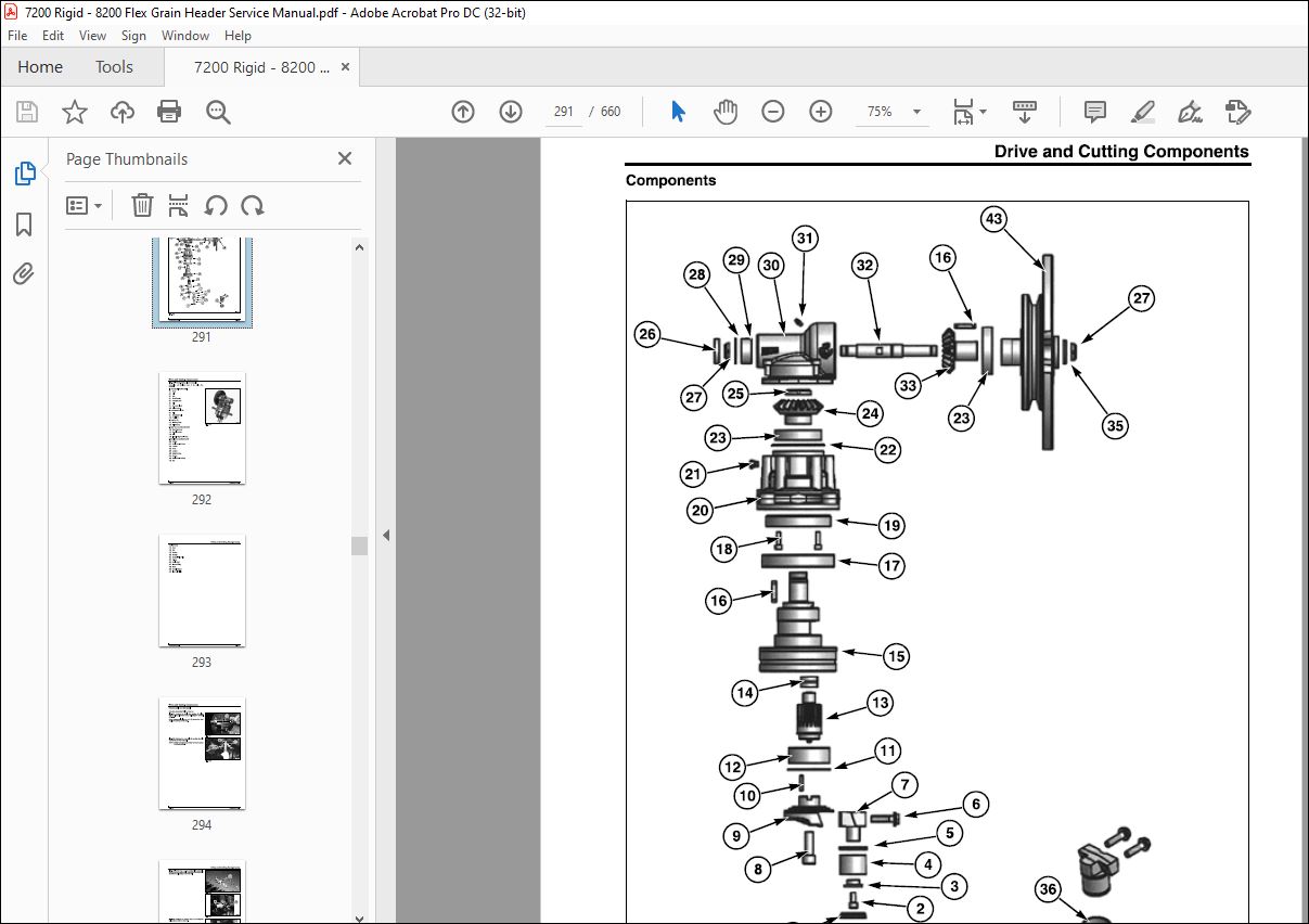
Components 02-209
Disassembly and Assembly 02-212
Installation 02-232
Auger 02-238
Auger Finger and Guide 02-238
Removal 02-241
Installation 02-243
Center Finger Crankshaft and Bearings 02-245
Long Crankshaft (Left) 02-259
Long Crankshaft (Right) 02-260
Support Rings 02-261
Right Auger Shaft 02-262
Left Auger (Gudgeon) Shaft 02-271
Flighting Extensions 02-275
Left Flange and Right Bulkhead 02-279
Left-Hand and Right-Hand Flighting 02-282
Auger Straightening 02-290
End Shields 02-291
Removal 02-291
Installation 02-301
Dividers 02-305
Extensions 02-305
Adjustments 02-313
Left Divider 02-315
Right Divider 02-323
Header Weights 03-3
Removal 03-3
Installation 03-4
Closure Extensions with Integral Straw Retarder 03-6
General Information 03-6
Removal 03-8
Installation 03-13
Seal Strip 03-18
Storage 03-18
Removal 03-18
Installation 03-19
Adjustable Stripers 03-20
Adjustment 03-20
Angle Retarders 03-21
Adjustment 03-21
Removal 03-22
Installation 03-24
Smart Trac Sensors 03-26
Wiring (Header) 03-26
Removal 03-30
Installation 03-32
Rock Guards (Rigid Header) 03-34
Removal 03-34
Installation 03-37
Left-Hand End Panel 03-38
Removal 03-38
Installation 03-54
Right-Hand End Panel 03-72
Removal 03-72
Installation 03-86
Header Bottom Replacement 03-103
Removal 03-103
Installation 03-115
Tilt Arm Replacement 03-126
Removal 03-126
Installation 03-130
Bat Reel 04-3
Bat Pitch 04-3
Removal 04-3
Disassembly 04-6
Inspection and Repair 04-7
Assembly 04-9
Installation 04-16
Pickup Reel (HCC) 6 BAT Level 2 04-21
Removal 04-21
Disassembly 04-24
Inspection 04-25
Assembly 04-28
Installation 04-45
Reel Support Arm 04-50
Removal 04-50
Reel Carrier Assembly 04-62
Installation 04-64
Power (Electric) Reel Fore and Aft 04-78
Removal 04-78
Assembly and Installation 04-80
Reel Lift Cylinders 04-83
Hydraulic Schematic 04-83
Removal and Installation 04-85
Single Point Mobile Connector (Header) 04-86
Reel Drive (Hydraulic) 04-87
Hydraulic Schematic 04-87
Reel Speed Pickup 04-90
Removal (Motor) 04-93
Disassembly and Assembly 04-96
Installation (Motor) 04-101
INDEX
More products