$35
Greer ELEMENT DISPLAY Operation, Calibration & Troubleshooting Manual – PDF DOWNLOAD
Greer ELEMENT DISPLAY Operation, Calibration & Troubleshooting Manual – PDF DOWNLOAD
FILE DETAILS:
Greer ELEMENT DISPLAY Operation, Calibration & Troubleshooting Manual – PDF DOWNLOAD
Language : English
Pages : 76
Downloadable : Yes
File Type : PDF
IMAGES PREVIEW OF THE MANUAL:
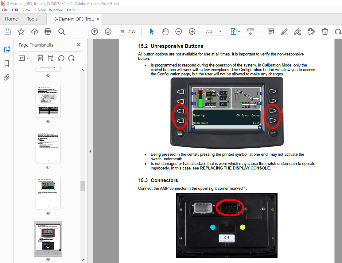
TABLE OF CONTENTS:
Greer ELEMENT DISPLAY Operation, Calibration & Troubleshooting Manual – PDF DOWNLOAD
SECTION I: OPERATION 5
1 0 Outline of Operation 5
1 1 System Components 5
1 2 Display Unit 5
1 3 Reeling Drum Assembly 6
1 4 Pressure Transducers 6
1 5 Anti-Two Block (ATB) 6
1 6 Function Kick-Out (FKO) 6
1 7 Operator Programmable Alarms 6
1 8 Outrigger Position Sensing 6
1 9 Electronic Frame-Level Sensor (If Equipped) 7
2 0 System Self-Test 7
3 0 Start Up Screen 7
4 0 System Setup 8
4 1 Frame-Level Screen (If Equipped) 8
4 2 Accessing the Configuration Screen 11
5 0 The Configuration Screens 12
5 1 Pick Point 13
5 2 POL 14
5 3 Aux Head 15
5 4 Jib 16
5 5 Boom Mode 17
5 6 Stow 18
5 7 Counter Weight 19
5 8 Winch 20
5 9 Home 20
5 10 Next 21
5 11 Outrigger 21
5 12 Man Basket 22
5 13 Tires 22
5 14 Rigging Travel (Tires sub-menu) 23
6 0 The Home Screen 24
3
W450780r0 8/2016
6 1 Adjusting the Brightness of the Display 25
6 2 LMI Window 26
6 3 Crane Configuration Window 27
7 0 Cancel Alarm Button 28
7 1 Reset Function Kickout 28
8 0 Operator Programmable Alarms 29
8 1 Accessing the Operator Alarms 29
8 2 Setting Minimum Boom Angle Alarm 30
8 3 Setting Maximum Boom Angle Alarm 30
8 4 Setting Maximum Boom Length Alarm 31
8 5 Setting Maximum Tip Height Alarm 32
8 6 Swing Alarms 33
8 7 Accessing the Swing and Work Area Alarms 34
8 8 Setting the Swing Alarms 34
8 9 Work Area Selection Mode 35
8 10 Setting the Work Area Alarm 36
SECTION II: CALIBRATION & TROUBLESHOOTING 37
9 0 Introduction 37
9 1 Overview and Preparation 37
10 0 System Self-Test 38
11 0 Display Console Problems 39
12 0 Fault Reporting and Fault Codes 40
12 1 Group “A” Fault Codes 41
12 2 Group “B” Fault Codes 41
12 3 Group “C” Fault Codes 42
12 4 Group “D” Fault Codes 42
13 0 “No Fault Code” Problems 43
13 1 Anti-Two-Block Alarm (ATB) 43
13 2 Displayed Load or Radius Errors 43
14 0 Computer Unit Overview 46
14 1 Internal Status Indicators 46
14 2 Function Kickout Fuse (FUS1) 47
14 3 Replacing the Computer Unit 47
15 0 Display Console Overview 48
4
W450780r0 8/2016
15 1 Checking the Display Console 48
15 2 Unresponsive Buttons 49
15 3 Connectors 49
15 4 Horn 50
15 5 Moisture 50
15 6 Replacing the Display Console 50
16 0 Entering the Calibration Mode 51
16 1 Calibration Steps 52
16 2 Calibration Menus 53
16 3 Calibrating the Extension Sensor Zero 54
16 4 Calibrating the Angle Sensor Zero 55
16 5 Calibrating Span of Extension and Angle 56
16 6 Calibrating the Swing Potentiometer 59
16 7 Calibrating the Outrigger Position Sensors 61
16 8 Calibrating the Frame-Level Sensor (If Equipped) 64
16 9 After the Calibration Routine 66
17 0 Reeling Drum Overview 67
17 1 Checking the Reeling Drum Cable Layering 68
17 2 Sensor Baseplate Assembly 69
17 3 Anti-Two-Block Function Overview 71
17 4 Checking the Reeling Drum Cable 71
17 5 Checking the Anti-Two-Block Circuit 71
18 0 Swing Sensor Overview 73
18 1 Checking the Swing Sensor Drive Voltage 74
18 2 Checking the Swing Sensor Output Voltage 74
18 3 Checking the Swing Sensor Resistance 74
19 0 Frame-Level Sensor (If Equipped) 75
20 0 Revision History 76
More products