$35
Haulotte Forklift HS15E - HS4390E Operator's manual
Haulotte Forklift HS15E – HS4390E HS15E – HS4390E – HS15E PRO – HS4390E PRO – HS18E – HS5390E – HS18E PRO – HS5390E PRO Monochrome LCD Display Operator’s manual – PDF DOWNLOAD
FILE DETAILS:
Haulotte Forklift HS15E – HS4390E HS15E – HS4390E – HS15E PRO – HS4390E PRO – HS18E – HS5390E – HS18E PRO – HS5390E PRO Monochrome LCD Display Operator’s manual – PDF DOWNLOAD
Language : English
Pages :183
Downloadable : Yes
File Type : PDF
TABLE OF CONTENTS:
Haulotte Forklift HS15E – HS4390E HS15E – HS4390E – HS15E PRO – HS4390E PRO – HS18E – HS5390E – HS18E PRO – HS5390E PRO Monochrome LCD Display Operator’s manual – PDF DOWNLOAD
Operator’s manual 1
HS15E – HS4390E – HS15E PRO – HS4390E 1
24203 0 1
X 1
USA 1
A 3
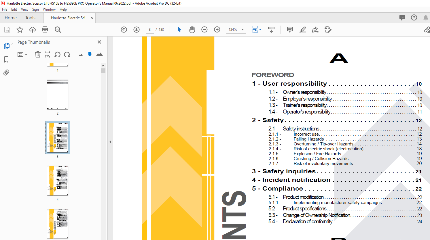
Foreword 3
1 – User responsibility 10 3
11 – Owner’s responsibility 10 3
12 – Employer’s responsibility 10 3
13 – Trainer’s responsibility 10 3
14 – Operator’s responsibility 11 3
2 – Safety 12 3
21 – Safety instructions 12 3
211 – Incorrect use 12 3
212 – Falling Hazards 13 3
213 – Overturning / Tip-over Hazards 14 3
214 – Risk of electric shock (electrocution) 18 3
215 – Explosion / Fire Hazards 19 3
216 – Crushing / Collision Hazards 19 3
217 – Risk of involuntary movements 20 3
3 – Safety inquiries 21 3
4 – Incident notification 21 3
5 – Compliance 22 3
51 – Product modification 22 3
511 – Implementing manufacturer safety campaigns 22 3
52 – Product specifications 22 3
53 – Change of Ownership Notification 23 3
54 – Declaration of conformity 24 3
B 3
Familiarization 3
1 – General safety 27 3
11 – Intended use 27 3
12 – Decal content 28 3
13 – Symbols and colors 30 3
14 – Level of severity 30 3
15 – Symbols legend and definitions 31 3
2 – Models description 32 3
3 – Primary machine components 34 3
31 – Layout 34 3
32 – Maintenance support 36 3
33 – Ground control box 38 3
331 – Layout 38 3
3311 – HAULOTTE Activ’Screen 2 41 3
3312 – Maintenance counter reset 60 3
34 – Platform control box 64 3
341 – Layout 64 3
4 – Performance Specifications 68 3
41 – Technical characteristics 68 3
42 – Working area / Range of motion 72 3
5 – Decals and markings locations 75 3
C 4
Pre-operation inspection 4
1 – Recommendations 91 4
2 – Working area assessment 91 4
3 – Inspection and Functional test 92 4
31 – Daily inspection 92 4
4 – Safety functional checks 95 4
41 – E-Stop button check 95 4
42 – Activation of controls 96 4
43 – Fault detector 96 4
431 – Indicators/LED’s test 96 4
432 – Buzzers test 97 4
44 – Automatic engine cut-out (If machine equipped with the option Range Extender) 97 4
45 – Oscillating axles (If equipped) 97 4
46 – Slope warning device 98 4
47 – Travel speed limitation 98 4
48 – On-board electronics 99 4
D 4
Operation instructions 4
1 – Operation 101 4
11 – Introduction 101 4
12 – Major description 101 4
13 – Operation from the ground control box 101 4
14 – Operation from the platform control box 102 4
15 – Mode operation 103 4
151 – Full Electric mode (If machine equipped with the option Range Extender) 103 4
152 – Auto mode (If machine equipped with the option Range Extender) 103 4
153 – Forced engine mode (If machine equipped with the option Range Extender) 104 4
154 – Overview of mode operation 105 4
2 – Ground control box 106 4
21 – To start and stop the machine 106 4
22 – Movement control 106 4
23 – Additional controls 106 4
3 – Platform control box 107 4
31 – To start and stop the machine 107 4
311 – To start the machine 107 4
312 – To stop the engine 107 4
32 – Drive and steer control 108 4
33 – Movement control 110 4
34 – Additional controls 110 4
341 – Activ’ Lighting System 110 4
4 – Rescue and emergency procedures 111 5
41 – In case of power loss 111 5
42 – To rescue operator in platform 111 5
421 – Operation of overriding system from ground control box 112 5
43 – No power available 113 5
431 – Manual emergency lowering procedure 113 5
5 – Transportation 115 5
51 – Transport configuration 115 5
52 – Machine stowage for transport – HS15 E (HS4390 E) – HS15 E PRO (HS4390 E PRO) – HS18 E (HS5390 E) – HS18 E PRO (HS5390 E PRO) 116 5
53 – Loading by ramp 117 5
54 – Folding guardrails 118 5
541 – Description 118 5
542 – Safety precautions 118 5
543 – Fold down operation 118 5
544 – Raising guardrails to working position 127 5
55 – Unloading 128 5
551 – Unloading by ramp 128 5
56 – Towing 129 5
561 – Brake release 130 5
57 – Storage 133 5
58 – Lifting operation 134 5
581 – Procedure for the use of slings HS15 E (HS4390 E) – HS15 E PRO (HS4390 E PRO) – HS18 E (HS5390 E) – HS18 E PRO (HS5390 E PRO) 134 5
6 – Cold Weather Recommendations 137 5
61 – Hydraulic oil 137 5
7 – Battery care and maintenance 138 5
71 – Locations 138 5
72 – Battery recharge 140 5
721 – On-board charger 140 5
722 – Battery charging 140 5
73 – Battery care and maintenance 144 5
731 – Filling batteries 144 5
7311 – Procedure to fill the batteries manually 145 5
7312 – Procedure to fill the batteries automatically – Option 146 5
732 – Desulfation charge 147 5
74 – Optimise battery life 148 5
E 6
General Specifications 6
1 – Machine dimensions 150 6
2 – Major component masses 153 6
3 – Acoustics and vibrations 154 6
4 – Wheels 155 6
41 – Technical specifications 155 6
42 – Inspection and maintenance 155 6
5 – Options 158 6
51 – Activ’Shield Bar Scissors – SECONDARY GUARDING SYSTEM (if the function is present and the device is installed in its support) 158 6
511 – Description 158 6
5111 – Summary of the indicator states 158 6
512 – Characteristics 159 6
513 – Safety precautions 160 6
514 – Pre-operation inspection 160 6
515 – Operation 161 6
5151 – Travel speed limitation ( Activ’Shield Bar Scissors option) 161 6
5152 – Raising speed limitation ( Activ’Shield Bar Scissors option) 162 6
516 – Specific decals 163 6
517 – Insert the console into its support 163 6
52 – Range Extender 165 6
521 – Description 165 6
522 – Characteristics 165 6
523 – Safety precautions 170 6
524 – Pre-operation inspection 170 6
525 – Installing / Removing the Range Extender 171 6
526 – Specific decals 173 6
53 – Fast Charge 174 6
531 – Description 174 6
532 – Safety precautions 174 6
533 – Specifications 174 6
534 – Operation 175 6
54 – Plate holder / Tube holder 176 6
541 – Description 176 6
542 – Characteristics 176 6
5421 – Plate holder usage 177 6
5422 – Tube holder usage 177 6
543 – Safety precautions 178 6
544 – Pre-operation inspection 179 6
545 – Disassembly – Assembly 180 6
546 – Operation 182 6
5461 – Plate/panel holder version 182 6
5462 – Tube/pipe holder version 184 6
547 – Strapping (Strap not provided) 186 6
548 – Storage of the supports on the platform 187 6
549 – Folding guardrails if machine equipped with plate/tube holder support 187 6
F 7
Maintenance 7
1 – General 189 7
2 – Maintenance Schedule 190 7
3 – Inspection program 191 7
31 – General program 191 7
32 – Daily inspection 192 7
33 – Periodic inspection 192 7
34 – Reinforced inspection 192 7
35 – Major inspection 193 7
4 – Repairs and adjustments 194 7
G 7
Other information 7
1 – Conditions of warranty 195 7
2 – Subsidiary contact information 195 7
21 – California warning 196 7
H 7
Intervention register 7
1 – Intervention register 199 7
Foreword 9
You have just purchased a HAULOTTE® product and we would like to thank you for your business 9
The aerial work platform is a device for lifting people designed and manufactured with the intent to enable users to access overhead elevated temporary workplaces with the necessary tools and equipment All other uses or alterations/ modifications to 9
This manual shall be considered a permanent component of the machine and shall be kept with the aerial work platform in the designated Manual Holder, at all times 9
Safe operation of this product can only be assured if you follow the operating instructions contained in this manual To ensure the safe and appropriate use of this equipment, only trained personnel are authorised to use and carry out maintenance on 9
We would particularly like to draw your attention to 2 essential points : 9
• Comply with safety instructions 9
• use this equipment within the performance limits specified by this user manual 9
With regard to the designation of our equipment, we stress that this is purely for commercial purposes and not to be confused with the technical specifications Only the specifications in this manual should be used to study the suitability of the equ 9
This operator’s manual is specific to the HAULOTTE® products listed on the cover page of this manual 9
The user manual does not replace the necessary training that is required for all of this machine’s operators HAULOTTE® has compiled this manual to assist in safe and efficient operation of the products covered in the manual 9
The manual must be available to all operators and must be kept in a legible condition Additional copies can be ordered from HAULOTTE Services® 9
Stay Safe and keep working with HAULOTTE® ! 9
For online reference and to download the manuals for your machines HAULOTTE®, go to : 9
https://wwwetechnical-informationcom 9
or, scan the QR Code below : 9
1 – User responsibility 10
11 – Owner’s responsibility 10
The owner (or hirer) has the obligation to : 10
All malfunctions and problems identified during the inspection shall be corrected before the aerial work platform is returned to service 10
12 – Employer’s responsibility 10
The employer (or plant superintendent) is required : 10
• Under the influence of drugs, alcohol, etc 10
• Subject to fits, convulsions, dizziness, etc 10
13 – Trainer’s responsibility 10
14 – Operator’s responsibility 11
The operator has the obligation to : 11
Operators must ensure that the inspections have been carried out by the owner and that they can use the machine for the purpose intended by the manufacturer 11
The operator has the obligation to stop using the machine in the event of malfunction or safety problems on the machine or in the work area and report the problem immediately to his/her supervisor 11
2 – Safety 12
21 – Safety instructions 12
211 – Incorrect use 12
212 – Falling Hazards 13
Before commencing operation : 13
To enter or exit from the platform : 13
When in the platform : 13
213 – Overturning / Tip-over Hazards 14
Before positioning and operating the machine : 14
By slope is meant the tilt of a surface in relation to the horizontal plane 16
WIND: the aerial work platform can be used up to the maximum wind speed indicated in the specifications in this manual To identify the local wind speed, use the Beaufort scale below, a wind gauge or an anemometer 17
Beaufort scale 17
214 – Risk of electric shock (electrocution) 18
The machine is not electrically insulated and does not provide protection from contact or proximity to electrically charged conductors 18
Always position all parts of the aerial work platform, the occupants, accessories and tools at a reasonable distance from power lines to ensure that no part of the work platform accidentally comes into contact with a power line 18
Apply local regulations pertaining to safety distances If this is not possible, follow the distances in the table below at a minimum : 18
Minimum safe approach distances 18
215 – Explosion / Fire Hazards 19
216 – Crushing / Collision Hazards 19
When in the platform : 19
• Check the driving direction with the help of the red or white arrows on the chassis and the platform control box 20
• Also note that when changing the driving direction (Forward <> Reverse) the joysticks or switches must return to the neutral position before reversing the drive direction and for movement to occur 20
• The occupants of the aerial work platform must wear personal protection equipment and comply with local regulations in force 20
• Operators must comply with the safety standards of the job site and the employer, as well as the applicable state regulations relating to the use of personal protective equipment 20
• All personal fall protection equipment (PFPE) must comply with current regulations, must be inspected and used in accordance with the manufacturer’s instructions 20
217 – Risk of involuntary movements 20
Never use a damaged or malfunctioning machine 20
Always respect the following rules : 20
3 – Safety inquiries 21
Inquiries relating to design criteria/specifications of a product, standards compliance, or overall machine safety should be sent to the HAULOTTE® PRODUCT SAFETY department 21
Each inquiry or request should include all relevant information; including contact name, telephone number, mailing address, email address, plus the machine model and serial number 21
The HAULOTTE® Product Safety department will evaluate each request/inquiry and will provide a written response 21
4 – Incident notification 21
Notify HAULOTTE® immediately when a HAULOTTE® product has been involved in an incident/ accident leading to personal injury or death, or when there is a major property damage 21
Connect to our website : wwwhaulottecom 21
5 – Compliance 22
51 – Product modification 22
It is strictly forbidden to modify a HAULOTTE® product Any modification may violate Haulotte design parameters, local regulations and industry standards 22
Any requests for modification must be formulated in writing (form) and be approved by the manufacturer 22
Do not hesitate to contact HAULOTTE Services®, should you have any questions relating to the issued bulletin(s) or with questions on the policy itself 22
511 – Implementing manufacturer safety campaigns 22
It is essential to implement the safety campaigns issued by the manufacturer All of these campaigns are accessible on our website 22
Connect to our website : wwwhaulottecom 22
52 – Product specifications 22
HAULOTTE® cannot be held liable for any changes to the technical characteristics/ specifications contained in this manual HAULOTTE® has a continuous improvement policy in place for its product range Given this policy, the Company reserves the rig 22
53 – Change of Ownership Notification 23
It is important and necessary to keep HAULOTTE Services® updated with current ownership of the machine This way, HAULOTTE® will be able to provide the necessary support for the product If you have sold or transferred this machine(s); it is your 23
Connect to our website : wwwhaulottecom 23
54 – Declaration of conformity 24
Declaration of conformity – Electric platforms 24
Declaration of conformity – Electric platforms 25
Familiarization 27
1 – General safety 27
11 – Intended use 27
Do not operate the product in the following situations : 27
• Check the allowable wind speed specified in the performace specifications tabulation 27
• Consult the Beaufort scale 27
12 – Decal content 28
The purpose of the labels on the machine is to alert the user to the conditions of use and risks related to aerial work platforms 28
Decals provide the following information : 28
Familiarize yourself with the decals and the hazard severity levels 28
The labels must be kept in good condition, otherwise they must be replaced 28
Familiarize yourself with the decals and their respective color codes 28
Additional decals can be ordered from HAULOTTE Services® 28
CE, UKCA, AS and EAC standards – Label warning risk 28
CE, UKCA, AS and EAC standards – Label informing about an important function of the machine 29
ANSI and CSA standards 29
13 – Symbols and colors 30
Symbols and colors are used to alert the operator of safety precautions and/or to highlight important safety information 30
The following safety symbols are used throughout this manual to indicate specific hazards and the hazard severity level when operating or maintaining the Aerial Work Platform 30
14 – Level of severity 30
15 – Symbols legend and definitions 31
Symbols are used throughout this manual to depict hazards, avoidance measures and indicate when information is required 31
Refer to the following table to familiarize yourself with these symbols 31
2 – Models description 32
Legend 32
3 – Primary machine components 34
31 – Layout 34
HS15 E (HS4390 E) – HS15 E PRO (HS4390 E PRO) – HS18 E (HS5390 E) – HS18 E PRO (HS5390 E PRO) 34
Universal plug connection 35
32 – Maintenance support 36
Placing the machine in operational configuration (Maintenance use) : 36
Placing the machine in the operational position (Excluding maintenance) : 37
33 – Ground control box 38
331 – Layout 38
General view 38
Controls and indicators 39
Upon starting and during operation of the machine, the LCD screen “Activ’Screen” located on the ground control box displays in real time the machine operating status 0
HAULOTTE Activ’Screen 2 0
HAULOTTE Activ’Screen 2 0
HAULOTTE Activ’Screen 2 0
HAULOTTE Activ’Screen 2 0
HAULOTTE Activ’Screen 2 0
HAULOTTE Activ’Screen 2 0
Controls and indicators 0
Controls and indicators 0
Controls and indicators 0
Controls and indicators 0
Controls and indicators 0
Controls and indicators 0
Controls and indicators 0
Controls and indicators 0
Controls and indicators 0
Controls and indicators 0
Controls and indicators 0
Controls and indicators 0
Controls and indicators 0
Controls and indicators 0
34 – Platform control box 47
341 – Layout 47
General view-HS15 E (HS4390 E) – HS15 E PRO (HS4390 E PRO) – HS18 E (HS5390 E) – HS18 E PRO (HS5390 E PRO) 47
Controls and indicators 48
4 – Performance Specifications 51
41 – Technical characteristics 51
Use the table to select the right Haulotte machine for the job 51
CE, UKCA, AS, EAC, CSA and ANSI A9220 standards 51
CE, UKCA, AS, EAC, CSA and ANSI A9220 standards 53
42 – Working area / Range of motion 55
HS15 E (HS4390 E) – HS15 E PRO (HS4390 E PRO) 55
HS18 E (HS5390 E) – HS18 E PRO (HS5390 E PRO) 56
5 – Decals and markings locations 58
CE, UKCA, AS and EAC standards : HS15 E – HS15 E PRO – HS18 E – HS18 E PRO 58
CE, UKCA, AS and EAC standards : HS15 E – HS15 E PRO – HS18 E – HS18 E PRO 59
CE, UKCA, AS and EAC standards : HS15 E – HS15 E PRO – HS18 E – HS18 E PRO 60
CE, UKCA, AS and EAC standards : HS15 E – HS15 E PRO – HS18 E – HS18 E PRO 61
CE, UKCA, AS and EAC standards : HS15 E – HS15 E PRO – HS18 E – HS18 E PRO 62
CE, UKCA, AS and EAC standards : HS15 E – HS15 E PRO – HS18 E – HS18 E PRO 63
CE, UKCA, AS and EAC standards : HS15 E – HS15 E PRO – HS18 E – HS18 E PRO 64
ANSI and CSA standards : HS4390 E – HS4390 E PRO – HS5390 E – HS5390 E PRO 66
ANSI and CSA standards : HS4390 E – HS4390 E PRO – HS5390 E – HS5390 E PRO 67
ANSI and CSA standards : HS4390 E – HS4390 E PRO – HS5390 E – HS5390 E PRO 68
ANSI and CSA standards : HS4390 E – HS4390 E PRO – HS5390 E – HS5390 E PRO 69
ANSI and CSA standards : HS4390 E – HS4390 E PRO – HS5390 E – HS5390 E PRO 70
ANSI and CSA standards : HS4390 E – HS4390 E PRO – HS5390 E – HS5390 E PRO 71
Pre-operation inspection 74
1 – Recommendations 74
The owner, the site manager, the supervisor and the operator are all responsible to ensure the machine is fit for the work it is to perform; ie that the machine is suitable to carry out the work in complete safety and in compliance with this Operat 74
Before using the machine, read the previous chapters in this manual Ensure that you have understood the following points : 74
• Safety precautions 74
• Operator’s responsibilities 74
• Conditions and the operating principles of the machine 74
2 – Working area assessment 74
Before any operation : 74
• Carry out a thorough inspection of the site to identify any potential risks within the work zone 74
• Take the necessary precautions to avoid collisions with other machinery within the work zone 74
Ensure that : 74
• The weather conditions (wind, rain, etc) allowing the machine to be used 74
• The ground withstands the weight of the machine and has not been affected by the poor weather conditions 74
• Check that the authorisations to work with the machine on the site in question have been obtained (g chemical product factories) 74
• Define a rescue plan for all the risks, including the risk of falls and crushing 74
3 – Inspection and Functional test 75
31 – Daily inspection 75
Each day before the beginning of a new work session and with each change of operator, the machine must be subjected to a visual inspection and a complete functional test 75
In case of loose fasteners, refer to torque table value in maintenance book 75
In case of leaks, replace the damaged part before use 75
In case of structural part deformation (cracks, broken weld, paint chips) replace the part before use 75
Sample of broken welds 75
We recommend these forms to be completed daily and stored to assist with your maintenance schedule 75
Each action is depicted in the daily inspection sheet using the following symbols 75
Use the detailed program below 75
HS15 E (HS4390 E) – HS15 E PRO (HS4390 E PRO) – HS18 E (HS5390 E) – HS18 E PRO (HS5390 E PRO) 76
HS15 E (HS4390 E) – HS15 E PRO (HS4390 E PRO) – HS18 E (HS5390 E) – HS18 E PRO (HS5390 E PRO) 77
4 – Safety functional checks 78
To protect the user and the machine, safety systems prevent the movement of the machine beyond its operating limits These safety systems when activated immobilize the machine and prevent further movement 78
The operator must be familiar with this technology and understand that is not a malfunction but an indication that the machine has reached an operation limit 78
Aerial Work platforms are equipped with two control boxes which allow operators to safely use the machine An auxiliary system (Overriding system) is available on the ground control box in order to rescue anyone trapped on the platform 78
The following checks describe the operation of the machine and the specific controls required 78
For the location and description of these controls : refer to section B 32 and D 2 – Ground control box and B 33 and D 3 – Platform control box 78
41 – E-Stop button check 78
Machine switched on : 78
Ground control box E-stop button 78
Platform control box E-stop button 78
42 – Activation of controls 79
The enable switch must be active to allow any movement 79
The “Enable Switch” system depends on the machine configuration and will consist of one of the following : 79
43 – Fault detector 79
The machine is equipped with an on-board fault detection system, which indicates the type of fault to the operator 79
The fault is identified by a default code 79
The default code is displayed at the ground control box 79
According to the type of fault, the machine MAY switch into DOWNGRADEMODE mode and certain movements are prevented to maintain Operator’s safety 79
Do not use the machine until the fault has been corrected 79
431 – Indicators/LED’s test 79
From the ground control box 79
From the platform control box 79
432 – Buzzers test 80
From the ground control box 80
44 – Automatic engine cut-out (If machine equipped with the option Range Extender) 80
If the machine is in Forced Mode , the engine automatically cuts out in the following conditions : 80
45 – Oscillating axles (If equipped) 80
To improve the driving capability on rough terrain, the front axle is equipped with an oscillating mechanism When the scissor arms are folded, the oscillating axle is unlocked to adapt to uneven ground and help machine stability When the scissor a 80
A visual inspection must be performed to ensure the absence of leaks from the oscillating cylinder and associated plumbing connections including the hydraulic hoses 80
A periodic inspection of this device must be conducted according to the recommendation in the maintenance schedule 80
46 – Slope warning device 81
From each control box, a buzzer alerts the operator that the machine is not folded/stowed and is positioned on a slope exceeding the slope allowed 81
When machine is on a slope greater than the rated slope, with extending structure out of the stowed position : 81
The lowering speed is reduced 81
In this case, fully fold the machine and place it on an authorized slope 81
To check the tilt sensor at ground level, perform the following steps : 81
Daily check 81
47 – Travel speed limitation 81
The machine has a selector of 3 driving speeds – low, medium and high 81
All driving speeds are authorised when the machine is folded, (machine in transport position) 81
The maximum travelling speeds are reduced when the following lifting height is reached : 81
When not in the above-described transport position, the low speed is engaged automatically 81
The electronic variable speed unit controls movement and driving speed 81
It receives information from the control joystick concerning the movements to be performed 81
It also manages the safety systems status 81
Poor knowledge of the characteristics and operation of the machine can lead the operator to think that a normal safety operation is a malfunction 81
On a slope, the speed decreases automatically 81
48 – On-board electronics 82
The machine is equipped with a specific calculator configured for this machine’s functionalities 82
Do not interchange the Calculator (calibration restoration) between machines 82
Operation instructions 84
1 – Operation 84
11 – Introduction 84
Only trained and authorized personnel shall be permitted to operate this aerial work platform 84
Prior to operation : 84
12 – Major description 84
All the machines are equipped with : 84
13 – Operation from the ground control box 84
• The emergency stop on the ground control box is not pushed in 84
• Ground control box is selected 84
• Beacon light (if fitted) 84
• When power is switched on 85
• Overload 85
• Slope if machine is out of stowed position 85
• Hydraulic oil overheating 85
• Movement buzzer option 85
• Drive buzzer option 85
14 – Operation from the platform control box 85
• The E-stop buttons on both ground and platform control boxes are not pressed in 85
• Platform control box selected from ground control box 85
A buzzer beeps in the following conditions : 85
15 – Mode operation 86
151 – Full Electric mode (If machine equipped with the option Range Extender) 86
When the machine is powered up, it will be in Full Electric Mode by default (Powered by battery and Range Extender off (if equipped with Range Extender)) 86
When the battery has less than 20 % charge, the following movements are disabled : 86
If the batteries are discharged below 5 %, no movement is available Recharging the batteries, either connected to the mains or when starting the Range Extender, is mandatory (Refer to Section D 7 – Battery care and maintenance) 86
The machine’s main power supply can only be switched off from the ground control box by turning the control box activation key selector ( 21 ) to OFF 86
152 – Auto mode (If machine equipped with the option Range Extender) 86
In this mode , the engine will automatically start or stop The level of charge in the batteries is managed to optimize their life by minimizing energy consumption with the use of the thermal engine Thereby, machine’s performance level is maintained 86
The thermal engine will start : 86
The machine’s power supply can only be turned OFF from the ground control box by turning the control box activation key selector ( 21 ) to the OFF position 86
If there is a fault in the Range Extender, the machine switches automatically to Full Electric mode 86
153 – Forced engine mode (If machine equipped with the option Range Extender) 87
This mode can be selected any time 87
The Range Extender will produce current to recharge the batteries up to the 100% 87
The motor stops automatically when battery recharging is complete 87
When the battery has less than 20 % charge, the following movements are disabled : 87
The machine’s power supply can only be turned OFF from the ground control box by turning the control box activation key selector ( 21 ) to the OFF position 87
If there is a fault in the Range Extender, the machine switches automatically to Full Electric mode 87
154 – Overview of mode operation 88
Energy management: use of batteries 88
2 – Ground control box 89
21 – To start and stop the machine 89
If the activation key selector for the control box ( 21 ) is activated, the machine is in Full Electric mode by default Refer to the section on operating modes 89
Mode operation 89
To shut-down the machine from the ground control box : 89
22 – Movement control 89
Ground box controls (emergency station) 89
23 – Additional controls 89
For the machines equipped with flashing light : 89
3 – Platform control box 90
31 – To start and stop the machine 90
311 – To start the machine 90
At the ground control box : 90
At the platform control box : 90
If the activation key selector for the control box ( 21 ) is activated, the machine is in Full Electric mode by default Refer to the section on operating modes : Mode operation 90
312 – To stop the engine 90
The engine stops and the machine returns to Full Electric mode if : 90
The machine’s power supply can only be turned OFF from the ground control box by turning the control box activation key selector ( 21 ) to the OFF position (Mode operation) 90
32 – Drive and steer control 91
Outriggers controls 92
33 – Movement control 93
34 – Additional controls 93
341 – Activ’ Lighting System 93
Refer to Section B 33 – Platform control box 93
The system Activ’ Lighting System illuminates the controls and the surrounding area of the machine Users can then safely move the machine 93
4 – Rescue and emergency procedures 94
41 – In case of power loss 94
In the event of power loss, control system failure or other malfunction, platform lowering functions may be accomplished manually 94
In an emergency, if the operator has to exit the platform while it is elevated, the transfer of the operator must respect the following recommendations : 94
42 – To rescue operator in platform 94
In a situation where an operator located in the platform needs to be rescued (for example in case of illness, injury or trapped against a structure making the control box inaccessible), the rescue personel at ground level needs to obtain rapid and di 94
HAULOTTE® has implemented a control system for safely lowering the operator to the ground in the event of an emergency to enable him to receive the neccessary treatment 94
Procedure : 94
421 – Operation of overriding system from ground control box 95
Procedure : 95
43 – No power available 96
Should the electrical controls or main power fail, it is possible to operate directly on the distributor using a mechanical lever 96
431 – Manual emergency lowering procedure 96
Valve 96
5 – Transportation 98
51 – Transport configuration 98
To climb the slope, move progressively the drive joystick 98
If the slope is too steep, use a winch in addition to traction 98
Do not place yourself below or too close to the machine during loading 98
The machine must be completely in the stowed configuration : 98
52 – Machine stowage for transport – HS15 E (HS4390 E) – HS15 E PRO (HS4390 E PRO) – HS18 E (HS5390 E) – HS18 E PRO (HS5390 E PRO) 99
HS15 E (HS4390 E) – HS15 E PRO (HS4390 E PRO) – HS18 E (HS5390 E) – HS18 E PRO (HS5390 E PRO) 99
Loading characteristics 99
Loading characteristics 99
53 – Loading by ramp100
54 – Folding guardrails101
541 – Description101
Folding guardrails system is designed to allow guardrails to be lowered to reduce the overall height of the machine101
This system facilitates moving the machine through low height doorways/passages101
542 – Safety precautions101
543 – Fold down operation101
Remove the platform control box from its starting position and set it aside in a safe place102
Order of folding for the guardrails, extensions retracted102
Guard rail front extension ( 1 )103
Support Activ’ Shield Bar Scisors :103
Front guardrail (1) :104
Front left guard rail ( 2 ) :105
Front right guard rail ( 3 ) :105
Guard rail rear extension ( 4 )106
Rear guard rail ( 4 ) :106
Rear left guard rail ( 5 ) :107
Rear right guard rail ( 6 ) :107
Left side guard rail ( 7 )108
Right side guard rail ( 8 )109
544 – Raising guardrails to working position110
To raise the folded guardrails to the vertical working position :110
55 – Unloading111
Before unloading, check that the machine is in good condition111
To reinstate the system, lift the platform a few centimetres (inches) from the ground control box111
551 – Unloading by ramp111
1 The machine is completely stowed111
2 Remove the tie downs111
3 Start the machine111
4 The ramp is in good condition and of sufficient capacity111
56 – Towing112
To tow a broken-down machine, release brake (Refer to : Brake release)112
Perform this operation on flat ground with wheels chocked112
In the towing configuration, the machine braking system is inactive Use a drawbar to avoid any risk of accident :112
561 – Brake release113
To tow a broken-down machine, perform manual brake release113
The brake release valve is located just above the rear axle :113
Check that the pressure is higher than 30 bar(435 psi) :114
As soon as the machine is towed to a safe, stable position, the parking brake must be immediately reactivated by unlocking the brake release valve :115
57 – Storage116
Do not store or immobilise the machine when it is unfolded116
Ensure all access panels, doors and side compartment covers are shut and secured116
58 – Lifting operation117
During loading / unloading operation with an overhead crane, it is important to respect the following :117
581 – Procedure for the use of slings HS15 E (HS4390 E) – HS15 E PRO (HS4390 E PRO) – HS18 E (HS5390 E) – HS18 E PRO (HS5390 E PRO)117
Attach 4 shackles of at least 5000 kg / 11,025 lb with the straps (5 m / 16 ft 5 in – 5000 kg / 11,025 lb) minimum to the 4 chassis rings118
Attach the slings using shackles118
6 – Cold Weather Recommendations120
In cold weather, do not store the machine with discharged batteries It is recommended that, at a temperature below 0 °C(32 °F) , the machine not be stored with a battery charge of below 75 % If you don’t have a power outlet, start the engine in F120
Set to Manual mode to start the engine to check that it is operating correctly If the engine does not start, do not keep trying for a prolonged period of time Allow the starter to cool down for a few minutes before trying again If the engine still120
In extreme cold conditions, machines should be equipped with optional cold start kits120
61 – Hydraulic oil120
External environmental conditions can reduce performance of the machine if the hydraulic oil temperature does not reach its optimum range120
It is recommended to use the hydraulic oil according to weather condition Refer to the table below120
7 – Battery care and maintenance121
71 – Locations121
72 – Battery recharge123
721 – On-board charger123
The on-board charger is used to charge the semi-drive batteries The charger’s power is 3000W and the maximum intensity is 16A for 220V – 240V and 110V networks Battery charging starts as soon as it is connected via the mains supply123
722 – Battery charging123
Machine settings / Machine configuration / Option setting / Battery charge configuration /124
Machine settings / Machine configuration / Option setting / Battery charge configuration / Single-phase125
Machine settings / Machine configuration / Option setting / Battery charge configuration / Three-phase126
Duration of charge cycle :126
The charge cycle stops automatically when charging is complete126
It can take up to 24 hours for a full charge if the battery levels are very low (Charge status less than 5 %) ; except option Range Extender126
73 – Battery care and maintenance127
731 – Filling batteries127
Single-Point Watering System127
Completely charge the batteries before connecting the distilled-water-filling unit127
1 Launch a full charge of the battery and check the charge indicator128
2 Disconnect the batteries charger and put back the plug in its housing128
3 Accessing batteries (Refer to section : Battery care and maintenance)128
4 Immerse the filtered inlet ( 2 ) of the transparent hose ( 4 ) fitted with a hand pump ( 3 ) in a demineralized water canister(Not supplied with the machine)128
5 Press the hand pump ( 3 ) to prime it until the water rises in the hose ( 4 )128
6 Once the hand pump ( 3 ) is primed, remove the male connector ( 8 ) cap ( 7 ) from the black supply tube assembly128
7 Connect the female connector ( 5 ) quick-hitch from the centralized filling system, including the hand-pump, to the male connector ( 8 )128
8 Press firmly on the hand pump to bring the distilled water to the batteries ( 1 )128
9 When the bulb ( 3 ) becomes resistant, this means that all the battery cells are filled appropriately128
10 Then uncouple the female connector ( 5 ) from the male connector ( 8 ) filling tube by pressing on the yellow button ( 6 ), then replace the cap ( 7 ) on the machine hose128
11 Close the machine covers128
12 Do not let the can to connect after filling is finished because this could cause the batteries to overfill128
1 Accessing batteries (Refer to section : Battery care and maintenance)129
2 Loosen the filling cap ( 1 )129
3 Fill the can with demineralized water129
4 Refit the filling plug again129
5 Close the machine covers129
6 Fully recharge the batteries in order to restart an automatic filling or activate the forced filling from the Activ’Screen of the ground control box129
732 – Desulfation charge130
Normal battery use leads to sulfatation of the lead plates during discharge (Formation of lead sulfate) Recharging the battery dissolves the lead sulfate The plates are desulfated130
Moreover, sulfatation also appears if the battery self-discharges during storage in a low state- of-charge (< 70%)130
As the battery ages, the lead sulfate may become harder and harder and increasingly difficult to eliminate by normal charging This leads to a loss of autonomy The desulfation charge is a way of regenerating the battery130
Procedure :130
74 – Optimise battery life131
To optimize battery performance and life-time, you are advised to follow the recommendations below :131
Keep the top of the batteries clean and dry Incorrect connection or corrosion may cause a high loss of power131
General Specifications132
1 – Machine dimensions133
Stowed / Transport position : Configuration that takes the minimum floor space necessary for storage and / or delivery of the machine – Access position – HS15 E (HS4390 E) – HS15 E PRO (HS4390 E PRO) – HS18 E (HS5390 E) – HS18 E PRO (HS5390 E PRO)133
Overall dimension specifications134
Overall dimension specifications134
Overall dimension specifications135
2 – Major component masses136
3 – Acoustics and vibrations137
The acoustics and vibrations specifications are based upon the following conditions :137
• The airborne noise emissions at workstation are determined per European Directive 2006/42/CE137
• The guaranteed sound power level LWA (displayed on the product) is determined per European Directive 2000/14/CE137
• The vibrations transmitted by the machinery to the hand/arm system and to the whole body are determined per European Directive 2006/42/CE137
4 – Wheels138
41 – Technical specifications138
42 – Inspection and maintenance138
Wheels replacement must be made in the following cases :138
Procedure of replacement :140
5 – Options141
51 – Activ’Shield Bar Scissors – SECONDARY GUARDING SYSTEM (if the function is present and the device is installed in its support)141
511 – Description141
512 – Characteristics142
513 – Safety precautions143
514 – Pre-operation inspection143
In addition to all the functional tests specific to the machine and to ensure that the Activ’Shield Bar Scissors system operates correctly, carry out the following operations :143
(1) : Reset = Bar lifted + Joystick returned to neutral143
515 – Operation144
The machine has 3 drive speeds :144
2 other speeds are activated automatically depending on the conditions of use :144
Poor knowledge of the characteristics and operation of the machine can lead the operator to think that a normal safety operation is a malfunction144
Machine stowed (Transport position) :144
• All travel speeds ( PV, MV, GV ) are permitted in forward mode Only ( PV, MV ) are available in reverse144
• The Activ’Shield Bar Scissors system is inactive ( Activ’Shield Bar Scissors indicator light is off)144
• The Activ’Shield Bar Scissors system is inactive ( Activ’Shield Bar Scissors indicator light is off)144
• Only low and average speeds ( PV, MV ) are permitted in the 2 directions144
• Selecting high speed ( GV ) automatically activates average speed ( MV )144
Machine unfolded (Out of transport position) :144
• The Activ’Shield Bar Scissors system is active in reverse144
• Whatever the speed selected :144
• Forward movement is done at “Micro Speed”144
• Rear movement is done at “Nano Speed”144
• The Activ’Shield Bar Scissors system is inactive ( Activ’Shield Bar Scissors indicator light is off)144
• Only “Nano Speed” is active in the 2 movement directions144
The machine has 2 speeds that activate automatically depending on the conditions of use :145
The top control console is attached to its support (Normal operation) :145
The upper control console is not in its support :145
516 – Specific decals146
Section B 5Decals and markings locations146
517 – Insert the console into its support146
Activ’ Shield Bar Scissor instructions146
1 — Locate notches ( 1 ) and ( 2 ) on the support Activ’ Shield Bar Scissor146
2 — On the console, locate the identifying mark ( 1 )146
3 — Position mark ( 1 ) on the control panel vertically in mark ( 1 ) of the support147
4 — Tilt the control console and snap it into the position marked ( 2 ) on support Activ’ Shield Bar Scissor147
5 — To remove the console, carry out the steps in reverse order Press on the lock to unlock it147
52 – Range Extender148
521 – Description148
This option is designed to charge the machine independently if a power network is not available nearby148
This option is used to power tools in the sockets on the RANGE EXTENDER control panel or to power the platform supply option (if present on the machine)148
All lifting and forward movements are possible with a machine equipped with the Range Extender system, as long as the batteries have a sufficient charge level148
522 – Characteristics148
Range Extender — 1148
Range Extender — 2149
Range Extender — 3150
Range Extender — 4151
Range Extender — 5151
523 – Safety precautions153
524 – Pre-operation inspection153
525 – Installing / Removing the Range Extender154
Fast charge connection155
Connect in the order indicated :155
Fast charge connection — From the mains155
Anti-theft system :155
Removal :156
526 – Specific decals156
Section B 5Decals and markings locations156
53 – Fast Charge157
531 – Description157
This option is designed to charge the machine from an available three-phase 380 V (250V US) power network to minimise the machine’s charge time157
Only the platform raising function and the stabilizers are available in this configuration157
532 – Safety precautions157
533 – Specifications157
534 – Operation158
Connect the 380 V (250V US) power cable to the socket ( 3 ) located on the machine158
The screen Activ’Screen switches to fast charge mode :158
54 – Plate holder / Tube holder159
541 – Description159
This accessory is an assembly designed to transport plates, pipes and tubes This accessory is composed of 2 supports positioned and attached on the guardrails of the platform extensions This accessory is held in position by means of pins159
The plates, tubes or pipes must be positioned on the supports and firmly attached to them using fasteners such as lashing straps (not provided)159
542 – Characteristics159
543 – Safety precautions161
• The weight of the accessory161
• The weight of the load on the accessory161
• The weight of the operators161
• The weight of the tools and any other equipment on the work platform161
544 – Pre-operation inspection162
545 – Disassembly – Assembly163
546 – Operation165
Operate the plate stop to place it in different positions165
547 – Strapping (Strap not provided)169
548 – Storage of the supports on the platform170
549 – Folding guardrails if machine equipped with plate/tube holder support170
Storage of the supports on the work platform for transport :170
Assembly folded :170
Maintenance172
1 – General172
As an owner and/or operator of Haulotte equipment, your Safety is of utmost importance to HAULOTTE® , which is why HAULOTTE® places such a high priority on product safety172
INSPECTIONS are not only required by HAULOTTE®, but may also be required by industry standards and/or local regulations172
To ensure your equipment continues to achieve the level of performance set in the factory, it is important to maintain it regularly We remind you that it is strictly forbidden to make any modifications Regular and timely inspections will reduce equ172
Overview :172
• Walk-around inspections take only a few minutes at the beginning and end of each shift – one of the best ways to prevent mechanical problems and safety hazards172
What to Do :172
• Use your senses: sight, smell, hearing and touch172
Frequency :172
• Check your machine periodically during your entire workday172
• Make sure to do your inspection the same way every time172
• Complete one of these inspections at the start and end of each shift172
It is the owner’s responsibility to ensure the required maintenance as recommended by Haulotte is completed prior to the operation of the machine172
If regular maintenance is not carried out, this may :172
• Void the warranty172
• Cause machine malfunction172
• Reduce machine reliability and shorten its service life172
• Jeopardize operator safety172
HAULOTTE Services® technicians are specially trained to carry out extensive repairs, interventions or adjustments on the safety systems or elements of HAULOTTE® machines They carry genuine HAULOTTE spare parts and tools as required, and also provi172
The inspection and maintenance table, identifies the role and the responsibilities of each party in periodical machine maintenance Section C 3 – Inspection and Functional test172
2 – Maintenance Schedule173
This section provides the necessary information needed to place the machine in safe operation In accordance with the regulations that are currently applicable, this machine is deisgned to have a 10 year life span in normal usage conditions The life173
Severity of operating conditions may require a reduction in time between maintenance periods Machines that have been out of service or have not been in use for more than 3 months must undergo a periodic inspection before the machine is put back into173
Maintenance must be carried out by a competent company or person familiar with mechanical procedures173
Maintenance operations performed must be recorded in a register / log book of the machine173
3 – Inspection program174
31 – General program174
The machine must be inspected on a regular basis at intervals of no less than once 1 per year The purpose of the inspection is to detect any defect which could lead to an accident during routine use of the machine Local standards and regulations ma174
HAULOTTE® requires Reinforced and Major Inspections to be carried out on the product to extend its service life174
Inspections must be carried out by a competent company or person174
The inspection results must be recorded in the safety register or machine log book controlled and overseen by the company manager This register or machine log book and the list of competent repair persons must be made available to the government wor174
32 – Daily inspection175
The Daily inspection includes a visual inspection, operational checks and testing of the safety systems This must be conducted by the operator before using the machine175
This inspection is the responsibility of the user Refer to Section C 31 – Daily inspection175
33 – Periodic inspection175
The Periodic inspection is a thorough evaluation of the operation and safety features of the machine175
It must be conducted before the sale / resale of the machine and/or at least once every year175
Local regulations may have specific requirements on frequency, and content of inspections175
The severity of operating conditions may require frequent inspections175
This inspection is the responsibility of the owner, and inspections must be carried out by a competent company or person175
This inspection is in addition to the daily inspection175
This inspection should also be conducted after :175
34 – Reinforced inspection175
The Reinforced inspection is a thorough evaluation of the machine’s structural components, to ensure proper functionality of the machine175
This evaluation must occur at a frequency of 5000 hours or every 5 years175
This inspection is the responsibility of the owner, and it must be conducted by a HAULOTTE Services® technician or by a competent company or person175
This inspection includes :175
35 – Major inspection176
The Major inspection is a thorough evaluation of the machine’s integrity and proper functioning; after a normal service life of 10 years176
This evaluation must take place after 10 years of operation and then repeated every 5 years thereafter176
The severity of operating conditions may require frequent inspections176
This inspection is the responsibility of the owner, and it must be conducted by a HAULOTTE Services® technician or by a competent company or person176
This inspection includes :176
4 – Repairs and adjustments177
Extensive repairs, interventions or adjustments on the safety systems or components must be performed by a HAULOTTE Services® technician Use original spare parts and components only177
HAULOTTE Services® will not take responsibility for any outcomes resulting from inferior services or repairs performed by other unauthorised personnel177
HAULOTTE® reminds that NO modifications SHALL be carried out without the written permission of HAULOTTE®177
Any unauthorised repairs/modifications will void HAULOTTE® warranty177
To check for safety campaigns, consult our website : wwwhaulottecom177
Other information178
1 – Conditions of warranty178
Our warranty conditions and extension contracts are now available on the websites of our sales network : wwwhaulottecom178
2 – Subsidiary contact information178
21 – California warning179
For the US destined machines (ANSI and CSA standards)179
For electric (battery operated) machines180
Intervention register182
1 – Intervention register182
The intervention register keeps a record of maintenance and repair work carried out inside or outside the maintenance programme182
IMAGES PREVIEW OF THE MANUAL:
More products