$34
Haulotte Forklift SIGMA 16 – SIGMA 46 SIGMA 16 PRO – SIGMA 46 PRO Monochrome LCD Operator’s Manual
Haulotte Forklift SIGMA 16 – SIGMA 46 SIGMA 16 PRO – SIGMA 46 PRO Monochrome LCD Display Operator’s Manual – PDF DOWNLOAD
FILE DETAILS:
Haulotte Forklift SIGMA 16 – SIGMA 46 SIGMA 16 PRO – SIGMA 46 PRO Monochrome LCD Display Operator’s Manual – PDF DOWNLOAD
Language : English
Pages :136
Downloadable : Yes
File Type : PDF
TABLE OF CONTENTS:
Haulotte Forklift SIGMA 16 – SIGMA 46 SIGMA 16 PRO – SIGMA 46 PRO Monochrome LCD Display Operator’s Manual – PDF DOWNLOAD
Operator’s manual 1
SIGMA 16 – SIGMA 46 – SIGMA 16 PRO – SIGMA 46 PRO 1
SIGMA 16 – SIGMA 46 SIGMA 16 PRO – SIGMA 46 PRO 1
USA 1
A 3
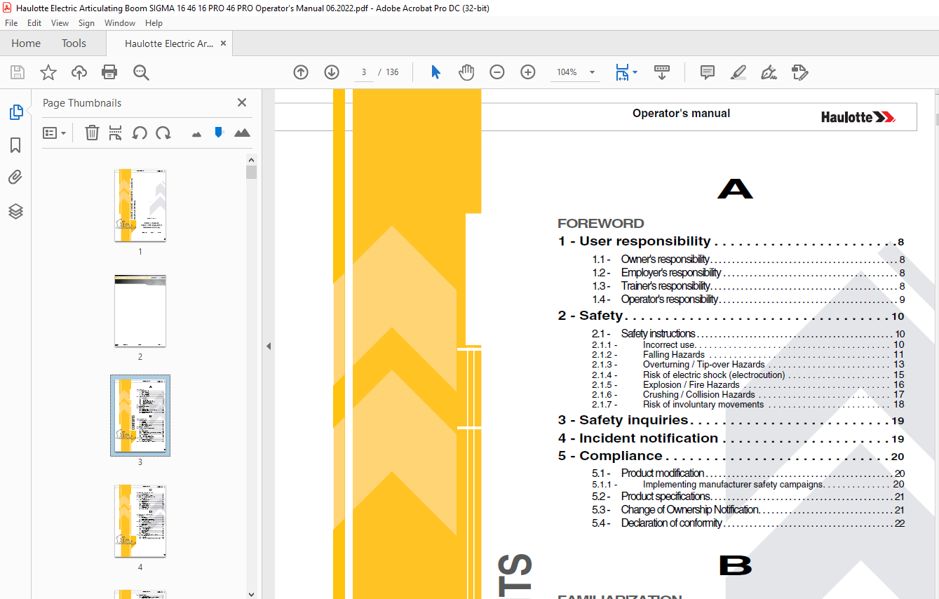
Foreword 3
1 – User responsibility 8 3
11 – Owner’s responsibility 8 3
12 – Employer’s responsibility 8 3
13 – Trainer’s responsibility 8 3
14 – Operator’s responsibility 9 3
2 – Safety 10 3
21 – Safety instructions 10 3
211 – Incorrect use 10 3
212 – Falling Hazards 11 3
213 – Overturning / Tip-over Hazards 13 3
214 – Risk of electric shock (electrocution) 15 3
215 – Explosion / Fire Hazards 16 3
216 – Crushing / Collision Hazards 17 3
217 – Risk of involuntary movements 18 3
3 – Safety inquiries 19 3
4 – Incident notification 19 3
5 – Compliance 20 3
51 – Product modification 20 3
511 – Implementing manufacturer safety campaigns 20 3
52 – Product specifications 21 3
53 – Change of Ownership Notification 21 3
54 – Declaration of conformity 22 3
B 3
Familiarization 3
1 – General safety 25 3
11 – Intended use 25 3
12 – Decal content 26 3
13 – Symbols and colors 28 3
14 – Level of severity 28 3
15 – Symbols legend and definitions 29 3
2 – Models description 30 3
3 – Primary machine components 32 3
31 – Layout 32 3
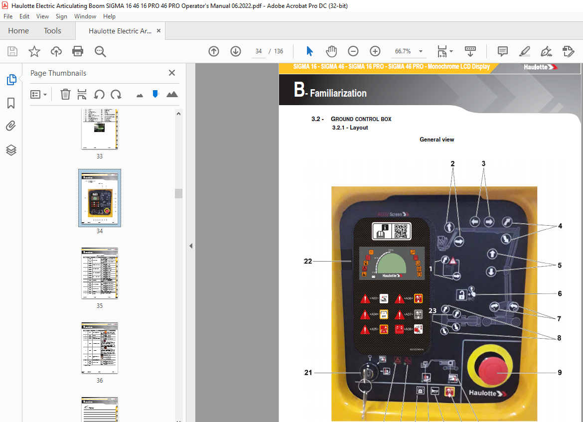
32 – Ground control box 34 3
321 – Layout 34 3
322 – HAULOTTE Activ’Screen 2 37 3
33 – Platform control box 54 3
331 – Layout 54 3
332 – Battery charging indicator (90) 56 3
333 – Display Panel (LED’S 101 – 116) 57 3
4 – Performance Specifications 59 3
41 – Technical characteristics 59 3
42 – Working area / Range of motion 61 3
5 – Decals and markings locations 63 3
C 4
Pre-operation inspection 4
1 – Recommendations 71 4
2 – Working area assessment 71 4
3 – Inspection and Functional test 72 4
31 – Daily inspection 72 4
4 – Safety functional checks 75 4
41 – E-Stop button check 75 4
42 – Activation of controls 75 4
43 – Fault detector 76 4
431 – Indicators/LED’s test 76 4
432 – Buzzers test 76 4
44 – Overload sensing system 77 4
45 – Slope warning device 77 4
46 – Travel speed limitation 78 4
47 – On-board electronics 78 4
D 4
Operation instructions 4
1 – Operation 79 4
11 – Introduction 79 4
12 – Major description 79 4
13 – Operation from the ground control box 80 4
14 – Operation from the platform control box 81 4
2 – Ground control box 83 4
21 – To start and stop the machine 83 4
22 – Movement control 84 4
23 – Additional controls 85 4
3 – Platform control box 86 4
31 – To start and stop the machine 86 4
311 – To start the machine 86 4
312 – To stop the machine 86 4
32 – Drive and steer control 87 4
33 – Movement control 88 4
34 – Additional controls 89 4
341 – Activ’ Lighting System 89 4
4 – Rescue and emergency procedures 90 4
41 – Main power supply failure 90 4
411 – Procedure 90 4
42 – To rescue operator in platform 91 4
421 – Operation of overriding system from ground control box 91 4
5 – Transportation 92 5
51 – Transport configuration 92 5
52 – Machine stowage for transport – SIGMA 16 – SIGMA 46 – SIGMA 16 PRO – SIGMA 46 PRO 93 5
53 – Unloading 95 5
54 – Towing 95 5
541 – Electric brake release 96 5
55 – Storage 98 5
56 – Lifting operation 99 5
6 – Cold Weather Recommendations 101 5
61 – Hydraulic oil 101 5
7 – Battery care and maintenance 102 5
71 – Battery recharge 102 5
711 – On-board charger 102 5
712 – Battery charging 103 5
72 – Battery care and maintenance 106 5
721 – Filling batteries 106 5
7211 – Procedure to fill the batteries manually – Option 107 5
7212 – Procedure to fill the batteries automatically – Option 109 5
722 – Desulfation charge 110 5
73 – Optimise battery life 111 5
E 5
General Specifications 5
1 – Machine dimensions 114 5
2 – Major component masses 116 5
3 – Acoustics and vibrations 116 5
4 – Wheel/Tire assembly 117 5
41 – Technical specifications 117 5
42 – Inspection and maintenance 117 5
5 – Options 119 5
51 – Swing gate 119 5
511 – Description 119 5
512 – Characteristics 119 5
513 – Safety precautions 119 5
514 – Pre-operation instructions 120 5
515 – Specific decals, optional 120 5
52 – Platform 121 5
53 – Plumber’s kit 122 5
531 – Description 122 5
532 – Characteristics 122 5
533 – Safety precautions 122 5
534 – Pre-operation inspection 123 5
535 – Operation 123 5
536 – Assembly – Dis-assembly 124 5
537 – Specific decals, optional 125 5
54 – Signalling cones holder 126 5
541 – Description 126 5
542 – Characteristics 126 5
543 – Safety precautions 126 5
544 – Pre-operation inspection 126 5
545 – Operation 127 5
546 – Assembly – Dis-assembly 128 5
55 – Neon tube holder 129 6
551 – Description 129 6
552 – Characteristics 129 6
553 – Safety precautions 129 6
554 – Pre-operation inspection 129 6
555 – Operation 130 6
556 – Assembly – Disassembly 131 6
56 – Activ’ Shield Bar – SECONDARY GUARDING SYSTEM 132 6
561 – Description 132 6
562 – Characteristics 132 6
563 – Safety precautions 133 6
564 – Pre-operation inspection 134 6
565 – Operation 135 6
566 – Specific decals 135 6
F 6
Maintenance 6
1 – General 137 6
2 – Maintenance Schedule 138 6
3 – Inspection program 139 6
31 – General program 139 6
32 – Daily inspection 139 6
33 – Periodic inspection 140 6
34 – Reinforced inspection 140 6
35 – Major inspection 141 6
4 – Repairs and adjustments 142 6
G 6
Other information 6
1 – Conditions of warranty 143 6
2 – Subsidiary contact information 143 6
21 – California warning 144 6
H 6
Intervention register 6
1 – Intervention register 147 6
Foreword 7
You have just purchased a HAULOTTE® product and we would like to thank you for your business 7
The aerial work platform is a device for lifting people designed and manufactured with the intent to enable users to access overhead elevated temporary workplaces with the necessary tools and equipment All other uses or alterations/ modifications to 7
This manual shall be considered a permanent component of the machine and shall be kept with the aerial work platform in the designated Manual Holder, at all times 7
Safe operation of this product can only be assured if you follow the operating instructions contained in this manual To ensure the safe and appropriate use of this equipment, only trained personnel are authorised to use and carry out maintenance on 7
We would particularly like to draw your attention to 2 essential points : 7
With regard to the designation of our equipment, we stress that this is purely for commercial purposes and not to be confused with the technical specifications Only the specifications in this manual should be used to study the suitability of the equ 7
This operator’s manual is specific to the HAULOTTE® products listed on the cover page of this manual 7
The user manual does not replace the necessary training that is required for all of this machine’s operators HAULOTTE® has compiled this manual to assist in safe and efficient operation of the products covered in the manual 7
The manual must be available to all operators and must be kept in a legible condition Additional copies can be ordered from HAULOTTE Services® 7
Stay Safe and keep working with HAULOTTE® ! 7
For online reference and to download the manuals for your machines HAULOTTE®, go to : 7
https://wwwetechnical-informationcom 7
or, scan the QR Code below : 7
1 – User responsibility 8
11 – Owner’s responsibility 8
12 – Employer’s responsibility 8
13 – Trainer’s responsibility 8
14 – Operator’s responsibility 9
2 – Safety 10
21 – Safety instructions 10
211 – Incorrect use 10
212 – Falling Hazards 11
213 – Overturning / Tip-over Hazards 13
Beaufort scale 14
214 – Risk of electric shock (electrocution) 15
Minimum safe approach distances 15
215 – Explosion / Fire Hazards 16
216 – Crushing / Collision Hazards 17
217 – Risk of involuntary movements 18
3 – Safety inquiries 19
4 – Incident notification 19
5 – Compliance 20
51 – Product modification 20
511 – Implementing manufacturer safety campaigns 20
52 – Product specifications 21
53 – Change of Ownership Notification 21
54 – Declaration of conformity 22
Declaration of conformity – Electric platforms 22
Declaration of conformity – Electric platforms 23
Familiarization 25
1 – General safety 25
11 – Intended use 25
12 – Decal content 26
CE, UKCA, AS and EAC standards – Label warning risk 26
CE, UKCA, AS and EAC standards – Label informing about an important function of the machine 26
ANSI and CSA standards 27
13 – Symbols and colors 28
14 – Level of severity 28
15 – Symbols legend and definitions 29
2 – Models description 30
Legend 30
3 – Primary machine components 32
31 – Layout 32
SIGMA 16 – SIGMA 46 – SIGMA 16 PRO – SIGMA 46 PRO 32
Universal plug 33
32 – Ground control box 34
321 – Layout 34
General view 34
Controls and indicators 35
322 – HAULOTTE Activ’Screen 2 0
HAULOTTE Activ’Screen 2 0
Controls and indicators 0
Controls and indicators 0
Controls and indicators 0
Controls and indicators 0
Controls and indicators 0
Controls and indicators 0
Controls and indicators 0
Controls and indicators 0
Controls and indicators 0
Controls and indicators 0
Controls and indicators 0
Controls and indicators 0
Controls and indicators 0
Controls and indicators 0
Controls and indicators 0
Controls and indicators 0
Controls and indicators 0
Controls and indicators 0
Controls and indicators 0
33 – Platform control box 0
331 – Layout 0
General view 0
Controls and indicators 0
332 – Battery charging indicator (90) 44
Battery charge status 44
333 – Display Panel (LED’S 101 – 116) 45
Upper control box display 45
4 – Performance Specifications 47
41 – Technical characteristics 47
CE, UKCA, AS, EAC, CSA and ANSI A9220 standards 47
42 – Working area / Range of motion 49
SIGMA 16 – SIGMA 46 49
SIGMA 16 PRO – SIGMA 46 PRO 50
5 – Decals and markings locations 51
CE, UKCA, AS and EAC standards – 4001102610 F – SIGMA 16 51
CE, UKCA, AS and EAC standards – 4001102620 F – SIGMA 16 PRO 52
CE, UKCA, AS and EAC standards 53
ANSI and CSA standards – 4001102950 F – SIGMA 46 55
ANSI and CSA standards – 4001102960 F – SIGMA 46 PRO 56
ANSI and CSA standards 57
Pre-operation inspection 59
1 – Recommendations 59
2 – Working area assessment 59
3 – Inspection and Functional test 60
31 – Daily inspection 60
Sample of broken welds 60
Electric articulated platforms 61
Electric articulated platforms 62
4 – Safety functional checks 63
41 – E-Stop button check 63
Ground control box E-stop button 63
Platform control box E-stop button 63
42 – Activation of controls 63
43 – Fault detector 64
431 – Indicators/LED’s test 64
From the ground control box 64
From the platform control box 64
432 – Buzzers test 64
From the ground control box 64
44 – Overload sensing system 65
45 – Slope warning device 65
To check the tilt sensor at ground level 65
46 – Travel speed limitation 66
47 – On-board electronics 66
Operation instructions 67
1 – Operation 67
11 – Introduction 67
12 – Major description 67
13 – Operation from the ground control box 68
14 – Operation from the platform control box 69
2 – Ground control box 71
21 – To start and stop the machine 71
22 – Movement control 72
Ground box controls (emergency station) 72
23 – Additional controls 73
3 – Platform control box 74
31 – To start and stop the machine 74
311 – To start the machine 74
312 – To stop the machine 74
32 – Drive and steer control 75
33 – Movement control 76
Foot Switch 76
34 – Additional controls 77
341 – Activ’ Lighting System 77
4 – Rescue and emergency procedures 78
41 – Main power supply failure 78
411 – Procedure 78
Manual repair – Marking (30) 78
42 – To rescue operator in platform 79
421 – Operation of overriding system from ground control box 79
5 – Transportation 80
51 – Transport configuration 80
52 – Machine stowage for transport – SIGMA 16 – SIGMA 46 – SIGMA 16 PRO – SIGMA 46 PRO 81
Turntable rotation pin – Locked 81
Turntable rotation pin – Unlocked 81
Machine stowing 82
Loading characteristics 82
53 – Unloading 83
54 – Towing 83
541 – Electric brake release 84
55 – Storage 86
56 – Lifting operation 87
Procedure for the use of slings 88
6 – Cold Weather Recommendations 89
61 – Hydraulic oil 89
7 – Battery care and maintenance 90
71 – Battery recharge 90
711 – On-board charger 90
Locations 90
712 – Battery charging 91
Machine settings / Machine configuration / Option setting / Battery charge configuration 91
Machine settings / Machine configuration / Option setting / Battery charge configuration 92
Charge screen 93
72 – Battery care and maintenance 94
721 – Filling batteries 94
7211 – Procedure to fill the batteries manually – Option 95
Single-Point Watering System 95
1 Launch a full charge of the battery and check the charge indicator 96
2 Disconnect the batteries charger and put back the plug in its housing 96
3 Unlock both locks 96
4 Remove the covers 96
5 Immerse the filtered inlet ( 2 ) of the transparent hose ( 4 ) fitted with a hand pump ( 3 ) in a demineralized water canister(Supplied with the machine) 96
6 Press the hand pump ( 3 ) to prime it until the water rises in the hose ( 4 ) 96
7 Once the hand pump ( 3 ) is primed, remove the male connector ( 8 ) cap ( 7 ) from the black supply tube assembly 96
8 Connect the female connector ( 5 ) quick-hitch from the centralized filling system, including the hand-pump, to the male connector ( 8 ) 96
9 Press firmly on the hand pump to bring the distilled water to the batteries ( 1 ) 96
10 When the bulb ( 3 ) becomes resistant, this means that all the battery cells are filled appropriately 96
11 Then uncouple the female connector ( 5 ) from the male connector ( 8 ) filling tube by pressing on the yellow button ( 6 ), then replace the cap ( 7 ) on the machine hose 96
12 Close the machine covers 96
13 Do not let the can to connect after filling is finished because this could cause the batteries to overfill 96
14 Place the cover in the correct position on the batteries 96
15 Unlock both locks on each side of the battery container 96
7212 – Procedure to fill the batteries automatically – Option 97
1 Open the cap 97
2 Fill the can with demineralized water 97
3 Close the cap properly 97
4 Fully recharge the batteries in order to restart an automatic filling or activate the automatic filling from the Activ’Screen of the ground control box 97
Navigation in the menus : 97
722 – Desulfation charge 98
73 – Optimise battery life 99
General Specifications101
1 – Machine dimensions102
Stowed / Transport position : Configuration that takes the minimum floor space necessary for storage and / or delivery of the machine – Access position – SIGMA 16 – SIGMA 46 – SIGMA 16 PRO – SIGMA 46 PRO102
2 – Major component masses104
3 – Acoustics and vibrations104
4 – Wheel/Tire assembly105
41 – Technical specifications105
42 – Inspection and maintenance105
5 – Options107
51 – Swing gate107
511 – Description107
Swing gate107
512 – Characteristics107
513 – Safety precautions107
514 – Pre-operation instructions108
515 – Specific decals, optional108
Location of the decals108
52 – Platform109
Technical specifications109
Sliding bar109
Swing gate109
53 – Plumber’s kit110
531 – Description110
532 – Characteristics110
533 – Safety precautions110
534 – Pre-operation inspection111
535 – Operation111
Strapping example(s)111
536 – Assembly – Dis-assembly112
537 – Specific decals, optional113
Location of the decals113
54 – Signalling cones holder114
541 – Description114
542 – Characteristics114
543 – Safety precautions114
544 – Pre-operation inspection114
545 – Operation115
546 – Assembly – Dis-assembly116
55 – Neon tube holder117
551 – Description117
552 – Characteristics117
553 – Safety precautions117
554 – Pre-operation inspection117
555 – Operation118
556 – Assembly – Dis-assembly119
56 – Activ’ Shield Bar – SECONDARY GUARDING SYSTEM120
561 – Description120
562 – Characteristics120
563 – Safety precautions121
564 – Pre-operation inspection122
565 – Operation123
566 – Specific decals123
Location of the decals123
Activ’ Shield Bar instructions – CE, UKCA, AS and EAC standards124
Activ’ Shield Bar instructions – ANSI and CSA standards124
Maintenance125
1 – General125
2 – Maintenance Schedule126
3 – Inspection program127
31 – General program127
32 – Daily inspection127
33 – Periodic inspection128
34 – Reinforced inspection128
35 – Major inspection129
4 – Repairs and adjustments130
Other information131
1 – Conditions of warranty131
2 – Subsidiary contact information131
21 – California warning132
For the US destined machines (ANSI and CSA standards)132
For electric (battery operated) machines133
Intervention register135
1 – Intervention register135
IMAGES PREVIEW OF THE MANUAL:
More products