$45
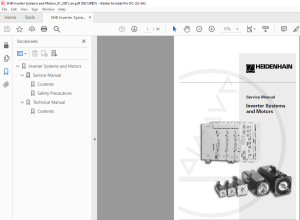
Heidenhain Inverter Systems and Motors Service Manual - PDF DOWNLOAD
Heidenhain Inverter Systems and Motors Service Manual - PDF DOWNLOAD
FILE DETAILS:
Heidenhain Inverter Systems and Motors Service Manual - PDF DOWNLOAD
Language :English
Pages :94
Downloadable : Yes
File Type : PDF
IMAGES PREVIEW OF THE MANUAL:
DESCRIPTION:
Heidenhain Inverter Systems and Motors Service Manual - PDF DOWNLOAD
1.1 Introduction
This Service Manual assists the service staff in troubleshooting and fault correction for HEIDENHAIN inverter systems, including motors that are driven with modular HEIDENHAIN controls (TNC 410 M, TNC 426 M, TNC 430 M and the lathe control MANUALplusM). For the technical information on the controls, please refer to the Service Manuals for:
TABLE OF CONTENTS:
Heidenhain Inverter Systems and Motors Service Manual - PDF DOWNLOAD
Table of Contents
Edition: Jan /2001 HEIDENHAIN Service Manual for Inverter Systems and Motors
1 The Service Manual for Inverter Systems and Motors 3
11 Introduction 3
12 Safety Precautions 4
13 Understanding Inverter Systems 5
14 Service Diagnosis 7
141 Checking the UM power modules or the power modules in the UE 8
2 UE 2xx Compact Inverter System 11
21 Hardware Components of the UE 2xx Compact Inverter System 11
22 UE 2xx Service Diagnosis 12
221 The control cannot be switched on with the machine Start button 12
222 Axis/spindle motor cannot be driven 14
23 UE 2xx Compact Inverter 16
231 Designation of the UE 2xx compact inverter 16
232 Overview of UE 2xx LEDs and connectors 17
233 Description of the UE 2xx LED display 17
234 Connections on the UE 2xx compact inverters 19
24 Toroidal Cores 21
25 PW Braking Resistor 22
26 UV 102 Power Supply Unit 23
3 UE 2xxB Compact Inverter System 25
31 Hardware Components of the UE 2xxB Compact Inverter System 25
32 UE 2xxB Service Diagnosis 26
321 The control cannot be switched on with the machine Start button 26
322 Axis/spindle motor cannot be driven 28
33 UE 2xxB Compact Inverter 31
331 Designation of the UE 2xxB compact inverter 32
332 Overview of UE 2xxB LEDs and connectors 32
333 Description of the UE 2xxB LED display 33
334 Connections on the UE 2xxB compact inverters 34
34 PW Braking Resistor 39
4 Modular Inverter Systems 41
41 Hardware Components of Modular Inverter Systems 41
42 Service Diagnosis for Modular Inverter Systems 42
421 The control cannot be switched on with the machine Start button 42
422 Axis/spindle motor cannot be driven 44
43 UM Power Modules 47
431 Description of the power module functions 47
432 Specifications 47
433 Designation of the UM 48
434 UM 1x1 Power modules 48
435 Power modules UM 1x2, UM 111B, UM 121B 49
436 Power modules UM 113 and UM 114 50
437 Description of the UM LED display 51
44 Modular Inverter System – With Regenerative Power Supply 52
441 UV 120/140 Power supply unit 52
442 Overview of UV 120/140 LEDs and connectors 53
443 Description of the UV 120/140 LED display 54
444 Connections on the UV 120/140 power supply units 55
445 Line filter and KDR 120/140 commutating reactor 57
446 Option: UP 110 braking resistor module 57
45 Modular Inverter System – Without Regenerative Power Supply 58
451 UV 130 Power supply unit 58
452 Overview of UV 130 LEDs and connectors 59
453 Description of the UV 130 LED display 60
454 Connections on the UV 130 power supply units 61
455 PW Braking resistor (pulse resistance module) 63
5 Non-HEIDENHAIN Inverter Systems
51 Hardware Components
52 Service Diagnosis for Non-HEIDENHAIN Inverter Systems
521 Axis/spindle motor cannot be driven
53 Interface Cards for SIMODRIVE 611D
531 Designation of the interface cards
54 Interface Card for One Axis in Single-Row Configuration (IdNo 324 955-xx) 541 Overview of LEDs and connectors (interface card IdNo 324 955-xx)
542 Grounding (interface card IdNo 324 955-xx)
543 Description of the LEDs (interface card IdNo 324 955-xx)
55 Interface Card for Two Axes in Single-Row Configuration (IdNo 313 437-xx) 551 Overview of LEDs and connectors (interface card IdNo 313 437-xx) 552 Grounding (interface card IdNo 313 437-xx)
553 Description of the LEDs (interface card IdNo 313 437-xx)
56 Interface Card with D-Sub Connections and Metallic Isolation (IdNo 324 952-1x) 561 Overview of LEDs and connectors (interface card IdNo 324 952-1x)
562 Grounding (interface card IdNo 324 952-1x)
563 Description of the LEDs (interface card IdNo 324 952-1x)
57 Interface Cards IdNo 324 952-0x Without Metallic Isolation
571 Overview of LEDs and connectors (interface card IdNo 324 952-0x)
572 Grounding (interface card IdNo 324 952-0x)
573 Description of the LEDs (interface card IdNo 324 952-0x)
58 Pin Layout for all Interface Cards
581 X1, X2 PWM connection to the UV 111x
582 X111, X112 PWM connection to the LE 583 X73 Enabling connector
59 UV Power Supply Units
591 UV 101B
592 UV 111
6 Motors
61 Description of the Motor Functions
611 Asynchronous motor
612 Synchronous motor
62 Test Routines for Motors
621 Checking the motor encoder
622 Replacing the motor encoder of an asynchronous motor
63 Axis Motor (QSY Synchronous Motor)
631 Designation of the QSY synchronous motor
632 Cables and connectors
633 Power connection for the HEIDENHAIN synchronous motors 64 Spindle Motor (QAN Asynchronous Motor)
641 Designation of the QAN asynchronous motor
642 Cables and connectors
643 Power connection for the HEIDENHAIN asynchronous motors
7 Testing Equipment
71 Overview
72 Drive Control Generator DCG (IdNo 296 737-01)
721 Description of the controls and displays of the DCG 722 DCG Accessories
73 PWM 8 Encoder Diagnostic Set (IdNo 309 956-xx)
S.M 6/3/2025
More products