$45
Heidenhain Inverter Systems & Motors Technical Manual - PDF DOWNLOAD
Heidenhain Inverter Systems & Motors Technical Manual - PDF DOWNLOAD
FILE DETAILS:
Heidenhain Inverter Systems & Motors Technical Manual - PDF DOWNLOAD
Language :English
Pages :700
Downloadable : Yes
File Type : PDF
IMAGES PREVIEW OF THE MANUAL:
DESCRIPTION:
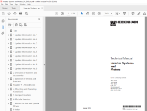
Heidenhain Inverter Systems & Motors Technical Manual - PDF DOWNLOAD
for the Contouring Controls
TNC 410 M
TNC 426 M
TNC 430 M
iTNC 530
MANUALplusM
MANUALplus 4110
CNC PILOT 4290
Foreword
- This Technical Manual has been written for all machine tool manufacturers. It contains all of the information necessary for the mounting and electrical installation of HEIDENHAIN inverter systems and HEIDENHAIN motors. With each update, you will receive a set of supplementary pages free of charge.
- Always sort these pages into your Technical Manual immediately. In this way, your manual will always be up-to-date. You can use extracts from this manual to supplement your machine documentation.
- If you increase the size of the manual format (17 cm x 24 cm) by the factor 1.225, you will have DIN A4 format. No documentation can be perfect. To stay up to date, documentation must change constantly. It is also thrives on your comments and suggestions for improvement. Please help us by telling us your ideas.
TABLE OF CONTENTS:
Heidenhain Inverter Systems & Motors Technical Manual - PDF DOWNLOAD
for the Contouring Controls
TNC 410 M
TNC 426 M
TNC 430 M
iTNC 530
MANUALplusM
MANUALplus 4110
CNC PILOT 4290
Titel 1
1 Update Information No 1 3
11 Compact Inverters 3
12 Modular Inverters 3
13 Motors 3
14 Replacing Instructions 4
1 Update Information No 2 5
11 Compact inverter 5
12 Modular Inverters 5
13 Motors 5
14 Replacing Instructions 6
1 Update Information No 3 7
11 General Information 7
12 Compact Inverters 7
13 Modular Inverter 7
14 Motors 7
15 Replacing Instructions 8
1 Update Information No 4 11
11 General Information 11
12 Modular Inverter 11
13 Motors 11
14 Replacing Instructions 12
1 Update Information No 5 13
11 Overview 13
12 Compact Inverters 14
121 Non-Regenerative Compact Inverters 14
122 Regenerative Compact Inverters 14
13 Modular Inverters 15
131 Non-Regenerative Power Supply Units 15
132 Regenerative Power Supply Units 15
133 Inverters 16
14 Accessories 17
15 Motors 18
151 Synchronous Motors 18
152 Asynchronous Motors 18
16 Technical Manual Documentation 19
17 Replacing Instructions 19
1 Update Information No 6 21
11 General Information 21
12 Power Supply Units 21
13 Power Modules 21
14 Motors 21
15 Accessories 22
16 Replacing Instructions 22
1 Update Information No 7 23
11 General Information 23
12 Accessories 23
13 Compact Inverters 30
14 Motors 37
1 Update Information No 8 46
11 General Information 46
12 Modular Inverters 47
1 Update Information No 9 48
11 Important Note 48
2 Overview of Inverters and Accessories 52
21 General Information 52
211 Designation of Inverter Systems 52
212 Electronic ID Labels 53
22 Overview of Inverter Systems 54
221 Non-Regenerative Compact Inverters 54
222 Regenerative Compact Inverters 54
223 Non-Regenerative Power Supply Units 55
224 Regenerative Power Supply Units 55
225 Inverter Modules 56
226 Accessories 57
23 Compact Inverters 58
231 Components of the Compact Inverter 58
232 UE1xx Compact Inverter 59
233 UE 2xx Compact Inverter 62
234 UE 2xxB Compact Inverter 64
235 UR 2xx(D) Compact Inverter 69
236 UV 106B Power Supply Unit 75
237 UV 105 Power Supply Unit 77
238 UV 102 Power Supply Unit 79
239 Toroidal Cores 80
2310 Ribbon Cables and Covers (Only for UE 2xxB, UR 2xx) 80
24 Modular Inverter 83
241 Components of the Modular Inverter 83
242 UV 130(D) Power Supply Unit 84
243 UV(R) 1x0(D) Power Supply Unit 87
244 UM 1xx(B)(D) Power Modules 92
245 Current Consumption of the Entire Inverter System103
246 Ribbon Cables and Covers104
25 Accessories for Compact Inverters and Modular Inverters110
251 PW 21x, PW 110(B), PW 120 Braking Resistors110
252 UP 110 Braking Resistor Module116
253 Line Filters119
254 Three-Phase Capacitor123
255 KDR 1x0(B) Commutating Reactor125
256 ZKF 1x0 DC-Link Filter132
257 SM 1xx Voltage Protection Module138
258 Coolant Connection142
259 Adapter Module143
2510 Axis-Enabling Module146
2511 Double-Row Configuration of HEIDENHAIN Components148
3 Selection of Motors and Inverters152
31 Performance Overview of a Complete Drive System152
32 Selection of the Axis Motor153
33 Selection of the Spindle Motor158
34 Selection of the Inverter159
35 Selection of the Braking Resistor160
Chapter 4 - Amendments 172
41 Check List172
42 General173
421 Trained Personnel173
422 Meaning of the Symbols Used173
423 General Safety Precautions174
424 General Electrical Protective Measures174
425 Intended Place of Operation175
426 Degree of Protection (IP Code)175
427 Connection to Different Types of Networks176
428 Adjusting the Line Voltage by Means of a Transformer178
429 Overvoltage Protector179
4210 Cross Sections of the Power Cables180
4211 Operating Modes182
43 EMC-Electromagnetic Compatibility184
431 Valid Regulations184
432 Likely Sources of Interference184
433 Power Supply Stability, Requirements184
434 CE mark185
435 Interference and Noise Immunity185
436 Noise Immunity185
437 Protective Measures186
44 Leakage Current from the Inverter Housing to the Grounding Connection187
45 Ambient Conditions188
451 Heat Generation and Cooling188
452 Humidity188
453 Climate Control Units189
454 Mechanical Vibration191
455 Contamination191
46 Water Cooling192
47 Mounting Attitude194
471 General194
472 Mounting Attitude of the HEIDENHAIN Inverter195
473 Mounting Attitude of the PW 1x0(B) Braking Resistor196
474 Mounting Attitude of the PW 21x Braking Resistor197
48 Connection Overviews200
481 Power Connection of Regenerative Inverter Systems200
482 Power Connection of Non-Regenerative Inverter Systems201
483 Adjustment to Different Types of Networks202
484 Arranging the Inverter Modules204
485 Arranging Additional Modules206
49 +5 V Power Supply and Bus Cable207
4 Mounting and Operating Conditions211
41 General Information211
411 Trained Personnel211
412 Meaning of the Used Symbols211
413 General Safety Precautions212
414 General Electrical Protective Measures212
415 Intended Area of Application213
416 Degree of Protection (IP Code)213
417 Connection to Different Types of Networks214
418 Adjusting the Line Voltage by Means of a Transformer216
419 Overvoltage Protector217
4110 Cross Sections of the Power Cables218
4111 Operating Modes220
42 EMC-Electromagnetic Compatibility222
421 Valid Regulations222
422 Likely Sources of Interference222
423 Power Supply Stability, Requirements222
424 CE Marking223
425 Interference and Noise Immunity223
426 Noise Immunity223
427 Protective Measures224
43 Leakage Current from the Inverter Housing to the Grounding Connection225
44 Environmental Conditions226
441 Heat Generation and Cooling226
442 Humidity226
443 Climate Control Units227
444 Mechanical Vibration229
445 Contamination229
45 Water Cooling230
46 Mounting Attitude232
461 General Information232
462 Mounting Attitude of the HEIDENHAIN Inverter233
463 Mounting Attitude of the PW 1x0(B) Braking Resistor234
464 Mounting Attitude of the PW 21x Braking Resistor235
47 Connection Overviews238
471 Power Connection of Regenerative Inverter Systems238
472 Power Connection of Non-Regenerative Inverter Systems239
473 Adjustment to Different Types of Networks240
474 Arranging the Inverter Modules242
475 Arranging Additional Modules244
48 +5 V Power Supply and Bus Cable245
5 Compact Inverters251
51 Connection Overview251
511 UE 110/UE 112 Compact Inverter252
512 UE 210 Compact Inverter253
513 UE 212 Compact Inverter254
514 UE 230 Compact Inverter255
515 UE 240 Compact Inverter256
516 UE 242 Compact Inverter257
517 UE 210B Compact Inverter258
518 UE 211B Compact Inverter259
519 UE 212B Compact Inverter260
5110 UE 230B Compact Inverter261
5111 UE 240B Compact Inverter262
5112 UE 242B Compact Inverter263
5113 UR 230 Compact Inverter264
5114 UR 230D Compact Inverter265
5115 UR 240 Compact Inverter266
5116 UR 240D Compact Inverter267
5117 UR 242 Compact Inverter268
5118 UR 242D Compact Inverter269
5119 Meaning of the LEDs270
5120 UV 106B Power Supply Unit275
5121 UV 105 Power Supply Unit276
5122 UV 102 Power Supply Unit277
52 Mounting and Connecting the Compact Inverter278
521 UE 2xx Compact Inverter278
522 UE 1xx, UE 2xxB, UR 2xx(D) Compact Inverters281
523 Mounting the Toroidal Cores286
53 Connecting the UE 2xx Compact Inverter290
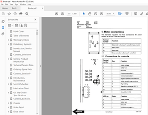
531 Power Supplies290
532 Motor Connections291
533 Main Contactor and Safety Relay292
534 PW 21x or PW 1x0(B) Braking Resistor for UE 2xx Compact Inverter293
54 Connecting the UE 1xx Compact Inverter296
541 Power Supplies296
542 Motor Connections298
543 Motor Holding Brakes298
544 Main Contactor and Safety Relay299
545 PWM Connection to the Control300
546 NC Supply Voltage and Control Signals301
55 Connecting the UE 2xxB and UR 2xx(D) Compact Inverters302
551 Power Supplies302
552 Motor Connections304
553 Connection of the Motor Holding Brakes304
554 Main Contactor and Safety Relay305
555 PWM Connection to the Control306
556 NC Supply Voltage and Control Signals307
557 Unit Bus308
558 PW 1x0(B) and PW 21x Braking Resistors for UE 2xxB Compact Inverter309
56 Connecting the UV 106B Power Supply Unit312
57 Connecting the UV 105 Power Supply Unit313
58 Connecting the UV 102 Power Supply Unit316
59 Connecting the UP 110 Braking Resistor Module317
510 Dimensions320
5101 UE 1xx320
5102 UE 2xx321
5103 UE 2xxB322
5104 UR 2xx(D)323
5105 UV 106B324
5106 UV 105325
5107 UV 102326
6 Modular Inverters329
61 Connection Overview329
611 UV 120 Power Supply Unit330
612 UVR 120D Power Supply Unit331
613 UV 130 Power Supply Unit332
614 UV 130D Power Supply Unit333
615 UVR 130D Power Supply Unit334
616 UV 140 Power Supply Unit335
617 UVR 140D Power Supply Unit336
618 UV 150 Power Supply Unit337
619 UVR 150 Power Supply Unit338
6110 UVR 150D Power Supply Unit339
6111 UVR 160DW Power Supply Unit340
6112 UVR 160D Power Supply Unit341
6113 Meaning of the LEDs of the Power Supply Units342
6114 UM 111 Power Module353
6115 UM 111D Power Module354
6116 UM 111B Power Module355
6117 UM 111BD Power Module356
6118 UM 112 Power Module357
6119 UM 112D Power Module358
6120 UM 113 Power Module359
6121 UM 113D Power Module360
6122 UM 114 Power Module361
6123 UM 114D Power Module362
6124 UM 115 Power Modules363
6125 UM 115D Power Modules364
6126 UM 116DW Power Modules365
6127 UM 121 Power Module366
6128 UM 121D Power Module367
6129 UM 121B Power Module368
6130 UM 121BD Power Module369
6131 UM 122 Power Module370
6132 UM 122D Power Module371
6133 Meaning of the LEDs on the UM 1xx372
6134 UV 105 Power Supply Unit373
62 Mounting and Connection of the Modular Inverter System374
63 Double-Row Configuration378
64 Connecting the UV 130(D) Power Supply Unit379
641 Power Supply379
642 Main Contactor and Safety Relay380
643 X90: 24-V Output (Only UV 130)381
644 NC Supply Voltage and Control Signals381
645 5-V Power Supply (Only UV130D)382
646 Unit Bus382
647 Connecting the Braking Resistor to the UV 130(D) Power Supply Unit383
65 Connecting the UV(R) 1x0(D) Power Supply Units385
651 Power Supply385
652 Main Contactor and Safety Relay388
653 NC Supply Voltage and Control Signals389
654 5-V Power Supply (Only UV(R) 1x0D)389
655 Unit Bus390
66 Connecting the UP 110 Braking Resistor Module392
67 Connecting the UM 1xx(B)(D) Power Modules394
671 PWM Connection to the Control394
672 Unit Bus395
673 Motor Connections396
674 Motor Holding Brakes396
68 Connecting the UV 105 Power Supply Unit398
69 Connecting the ZKF 1xx403
610 Connecting the Adapter Module405
611 Dimensions411
6111 UV 130(D)411
6112 UV 120, UVR 120D, UVR 130D412
6113 UV 140, UVR 140D, UV 150, UVR 150(D)413
6114 UVR 160DW414
6115 UVR 160D415
6116 UV 105416
6117 UM 111, UM 111D, UM 111BD, UM 121, UM 121D417
6118 UM 111B, UM 112(D), UM 121B(D), UM 122(D)418
6119 UM 113(D), UM 114(D)419
61110 UM 115(D)420
61111 UM 116DW421
7 Motors for Axis and Spindle Drives425
71 General Information425
711 Safety and Commissioning Regulations425
712 Data on the Name Plate427
72 Overview of Asynchronous and Synchronous Motors429
721 Asynchronous Motors, QAN Series430
722 Synchronous Motors, QSY Series431
723 Motors with Hollow Shaft, QAN xxxUH Series434
724 Cables and Connectors435
73 Different DC-Link Voltages442
74 Power Connection of the HEIDENHAIN Motors446
741 Synchronous Motors446
742 Asynchronous Motors448
75 Connecting the Speed Encoders453
76 Connecting the Holding Brake455
77 Connecting the Fan457
78 Mechanical Data459
781 Mounting Flange and Design459
782 Mounting the Motor460
783 Shaft End461
784 Rotatable Flange Sockets463
79 HEIDENHAIN Synchronous Motors, QSY Series467
791 Specifications - Synchronous Motors, QSY Series468
792 Dimensions - Synchronous Motors, QSY Series538
710 HEIDENHAIN Asynchronous Motors, QAN Series567
7101 Specifications - Asynchronous Motors, QAN Series568
7102 Dimensions - Asynchronous Motors, QAN Series595
711 HEIDENHAIN Motors with Hollow Shaft, QAN xxxUH Series612
7111 Dimensions -Motors with Hollow Shaft, QAN 2xxUH Series616
712 Permissible Forces on the Motor Shaft618
7121 General Information618
7122 QSY 10619
7123 QSY 20620
7124 QSY 96621
7125 QSY 116622
7126 QSY 130624
7127 QSY 155625
7128 QSY 190627
7129 QSY 041B629
71210 QSY 071B630
71211 QSY 090B631
71212 QSY 093B632
71213 QSY 112B633
71214 QSY 112C634
71215 QSY 112D635
71216 QAN 30636
71217 QAN 4S637
71218 QAN 200(UH)638
71219 QAN 260(UH)640
71220 QAN 320642
71221 QAN 104644
71222 QAN 134645
71223 QAN 164B646
713 SIEMENS Synchronous Motors, 1FK7xxx Series648
7131 1FK7042-5AF71650
7132 1FK7060-5AF71654
7133 1FK7063-5AF71658
7134 1FK7080-5AF71662
7135 1FK7083-5AF71666
7136 1FK7100-5AF71670
7137 1FK7101-5AF71674
7138 1FK7103-5AF71678
714 SIEMENS Hollow Shaft Motors, 1PM61xx-2DF81-1AR1-Z Series682
7141 Axial and Radial Forces - Hollow Shaft Motors, 1PM6105 and 1PM6133 Series685
7142 Dimensions - Hollow Shaft Motors, 1PM61xx-2DF81-1AR1-Z Series686
8 Index689
S.M 8/3/2025
More products