$45
Heidenhain iTNC 530 HSCI Service Manual 2012 - PDF DOWNLOAD
Heidenhain iTNC 530 HSCI Service Manual 2012 - PDF DOWNLOAD
FILE DETAILS:
Heidenhain iTNC 530 HSCI Service Manual 2012 - PDF DOWNLOAD
Language :English
Pages :654
Downloadable : Yes
File Type : PDF
IMAGES PREVIEW OF THE MANUAL:
DESCRIPTION:
Heidenhain iTNC 530 HSCI Service Manual 2012 - PDF DOWNLOAD
1 How to use the iTNC 530 HSCI Service Manual
1.1 Target group
This Service Manual has been written for specialist electricians for service, maintenance and
commissioning.
Specialists who perform work on the electrical system of a machine tool and its components must
have the required technical knowledge and competence.
Contents
This manual includes:
Specific explanations of the HEIDENHAIN Serial Controller Interface (HSCI)
Error messages and types of errors that indicate technical defects
Information on possible error causes
Descriptions for error diagnosis
Application descriptions of the diagnosis tools
Information on corrective action
Data backup instructions
Theoretical explanations of functions and their correlations
TABLE OF CONTENTS:
Heidenhain iTNC 530 HSCI Service Manual 2012 - PDF DOWNLOAD
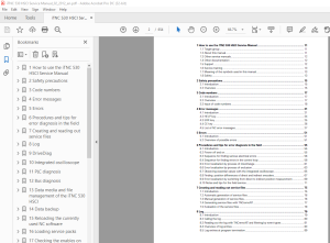
1 How to use the iTNC 530 HSCI Service Manual 11
11 Target group 11
12 About this manual 11
13 Other service manuals 12
14 Other documentation 12
15 Support 12
16 Service training 13
17 Meaning of the symbols used in this manual 13
18 Safety 13
2 Safety precautions 15
21 Introduction 15
22 Overview 15
3 Code numbers 17
31 Introduction 17
32 Overview 17
33 Input of code numbers 18
4 Error messages 21
41 Introduction 21
42 HELP key 24
43 ERR key 25
44 CE key 26
45 List of NC error messages 27
5 Errors 51
51 Introduction 51
52 Overview of possible errors 51
6 Procedures and tips for error diagnosis in the field 55
61 Introduction 55
62 Power off and on 55
63 Sequence for finding serious electrical errors 56
64 Sequence for finding errors in the control loop 58
65 Error localization by process of interchange 61
66 Error localization by process of exclusion 63
67 Observing essential values with the integrated oscilloscope 65
68 Finding position differences of direct and indirect encoders 67
69 Error localization by switching from direct to indirect position measurement 69
610 Notes and tips for the field service 71
7 Creating and reading out service files 75
71 Introduction 75
72 Automatic generation of service files 76
73 Manual generation of service files 76
74 Generating service files with TNCremoNT 77
75 Evaluation of the service files 78
8 Log 79
81 Introduction 79
82 Calling the log 80
83 Reading out the log with TNCremoNT and filtering by event types 81
84 Overview of log entries 83
85 Log entries at program termination 89
HEIDENHAIN Service Manual iTNC 530 HSCI
9 DriveDiag 91
91 Introduction 91
92 Activation and operation 91
93 Troubleshooting with DriveDiag 93
10 Integrated oscilloscope 95
101 Introduction 95
102 Activation and settings 96
103 Recording and adjusting the signals 101
104 Saving and loading recordings 106
105 For error diagnosis 107
1051 Triggering on error marker 107
1052 Circular interpolation test 109
1053 Finding compensation values 111
1054 Working with delta triggers 113
1055 Descriptions in this manual 114
11 PLC diagnosis 115
111 Introduction 115
112 Error messages 118
113 Possible error causes 118
114 Diagnosis tools in the PLC mode 119
1141 The ABLE function 119
1142 The LOGIC diagram 124
1143 The TRACE function 127
1144 The WATCH LIST function 128
1145 The I/O-FORCE LIST 131
115 Non-volatile PLC markers and words 134
116 Overviews 136
117 Specifications 144
1171 PLC inputs 144
1172 Analog inputs 144
1173 Inputs for Pt 100 thermistors 144
1174 PLC outputs 145
1175 Analog outputs 146
1176 Assignment of the inputs and outputs 146
12 Bus diagnosis 147
121 HSCI bus 147
1211 Introduction 147
1212 Possible error causes 147
1213 Calling and operating the HSCI bus diagnosis 148
1214 Identification of the PLC operands 149
1215 Read-back outputs 150
1216 Master, slaves and clients 152
1217 For error diagnosis 153
122 PROFIBUS 162
1221 Introduction 162
1222 Possible error causes 162
1223 Calling and operating the PROFIBUS diagnosis 163
1224 Identification of the PLC operands 164
1225 Troubleshooting with DriveDiag 164
1226 Log files 165
February 2012 HEIDENHAIN Service Manual iTNC 530 HSCI
13 Data media and file management of the iTNC 530 HSCI 167
131 Introduction 167
132 Structure of the data medium 168
133 Possible error causes 168
134 Test of the data medium 169
135 Setting the system time 173
136 Settings in the program manager 174
137 File management in the TNC partition 175
138 File management in the PLC partition 177
14 Data backup 181
141 Introduction 181
142 Connection setup 183
1421 Via Ethernet 183
1422 Via RS-232-C/V24 serial interface 192
1423 Via USB 195
143 Reading in and out individual files and directories 196
144 Backup on an external data medium 202
145 Extracting files from the backup file 206
146 Restoring data 207
147 Cable overview 209
1471 Ethernet interface RJ45 connection 209
1472 RS-232-C (V24) 210
148 Operating modes of the data interfaces 213
149 Drive symbols 214
15 Reloading the currently used NC software 215
151 Introduction 215
152 Preparations 215
153 Procedure 216
16 Loading service packs 219
161 Introduction 219
162 Preparations 220
163 Procedure 221
17 Checking the enables on the iTNC 530 HSCI 225
171 Introduction 225
172 Examination 228
1721 "Control is ready" output and input (EMERGENCY STOP chain) 228
1722 Axis-specific drive enable via axis groups 232
1723 Readiness of the inverter system 233
1724 PLC modules, markers and words for drive enabling 238
173 EMERGENCY STOP test during switch-on 240
18 Power supply 243
181 Introduction 243
182 Supply voltages in the HSCI system 243
183 PSL 130 low-voltage power supply unit 246
184 PSL 135 low-voltage power supply unit 250
185 Power supply for the MC 62xx computer unit 255
186 Buffer battery 257
187 Information menu 261
188 Power supply of the CC 61xx feedback control unit 262
189 Power supply of the UEC 11x feedback control unit 267
1810 Power supply of the MB 620 machine operating panel 268
1811 Power supply of the BF 250 visual display unit 269
1812 Power supply of the TE 6xx keyboard unit 270
1813 Power supply for the control-is-ready signal 271
HEIDENHAIN Service Manual iTNC 530 HSCI
1814 Power supply of the PLB 62xx system module 272
1815 Supply voltage for PLC outputs 274
18151 Introduction 274
18152 Supply voltage for PLC outputs on the UEC 11x 275
18153 Supply voltage for PLC outputs on the MB 620 275
18154 Supply voltage for PLC outputs on the PLB 62xx 275
18155 Supply voltage for PLC outputs on the PLD-H xx-xx-xx 276
19 Encoder interface 277
191 Position encoders 277
1911 Introduction 277
1912 Machine parameters 279
1913 Error messages 280
1914 Possible error causes 281
1915 Troubleshooting 281
1916 Possibilities with DriveDiag 289
1917 Possibilities with the integrated oscilloscope 290
1918 Corrective action 293
1919 Determining the field angle on linear motors,
torque motors and synchronous spindles 294
19110 Resetting the machine datum 295
19111 Restoring the spindle orientation 299
192 Speed encoders 300
1921 Introduction 300
1922 Machine parameters 302
1923 Error messages 303
1924 Possible error causes 303
1925 Troubleshooting 304
1926 Possibilities with DriveDiag 306
1927 Possibilities with the integrated oscilloscope 307
1928 Corrective action 310
1929 Readjusting the trip dog for reference end position 311
19210 Resetting the machine datum 312
19211 Restoring the spindle orientation 312
193 Error codes for encoders with EnDat interface 313
194 Further examination of position and speed encoders 314
195 Position measurement via motor encoder (indirect position measurement) 317
196 Switching over the position display for servicing 321
20 Reference run 323
201 Definition 323
202 Traversing the reference marks 324
203 Error messages 324
204 Possible error causes 324
205 Troubleshooting 325
206 Corrective action 326
207 Deselecting axes referencing 326
21 Interfaces to the drives 327
211 Digital PWM interface 327
2111 Introduction 327
2112 Machine parameters 330
2113 Tables for power supply modules, power stages and motors 332
2114 Reading out power module data 338
2115 Error messages 339
2116 Possible error causes 340
2117 Sequence for finding errors in the control loop 340
February 2012 HEIDENHAIN Service Manual iTNC 530 HSCI
2118 Error finding: Axes swapping 341
2119 Error finding: Swapping power modules
or output stages of the same type 343
21110 Error finding: Swapping the HEIDENHAIN expansion boards
for the SIMODRIVE 611 system 347
21111 Corrective action 348
212 Analog speed value interface 349
2121 Introduction 349
2122 Machine parameters 350
2123 Error messages 350
2124 Possible error causes 351
2125 Sequence for finding errors in the control loop 351
2126 Checking the analog speed value interface 352
2127 Adjusting the electrical offset (drift adjustment) 355
2128 Speed adjustment at the servo amplifier (tachometer adjustment) 358
2129 Corrective action 360
22 Visual display unit 361
221 Introduction 361
222 Possible error causes 362
223 Troubleshooting 363
224 Corrective action 364
23 Keyboard unit 365
231 Introduction 365
232 Signal paths in the console and to the MC 62xx 367
233 Possible error causes 369
234 Checking the keys 370
235 Checking the potentiometers 376
236 Checking the touchpad 380
237 Corrective action 381
238 Key matrix of the keyboard units 382
239 Key matrix of the screen soft keys 392
24 Machine operating panel 393
241 Introduction 393
242 Possible error causes 395
243 Checking the power supply 396
244 Checking the HSCI connection 396
245 Checking the keys 397
246 Checking the outputs 399
247 Corrective action 400
25 Handwheel 401
251 Introduction 401
252 Error messages 402
253 Possible error causes 402
254 Error diagnosis of HR 520 portable handwheel with display 404
255 Error diagnosis of HR 410 portable handwheel 409
256 Deselecting and disconnecting the portable handwheel 412
257 Error diagnosis of HR 130 panel-mounted handwheel 413
258 Corrective action 414
26 Touch probes 415
261 Introduction 415
262 Error messages 420
263 Possible error causes 420
264 Error diagnosis on TS touch probes 422
265 Error diagnosis on TT touch probes 427
HEIDENHAIN Service Manual iTNC 530 HSCI
266 Error diagnosis on the laser touch probe 431
267 Deselecting and disconnecting the touch probe 433
268 Corrective action 434
27 Features of HEIDENHAIN components 35
271 HEIDENHAIN components in a machine too 435
272 Hardware identification 436
273 Display of important system information 451
28 Connector designations and pin layouts 453
281 Important note 453
282 MC main computer 453
2821 Designations and positions of connectors 453
2822Pin layouts 455
283 CC controller unit 461
2831 Designations and positions of connectors 461
2832 Pin layouts 464
284 Controller unit with integrated UEC inverter 473
2841 Designations and positions of connectors 473
2842 Pin layouts 474
285 PLB basic modules 481
2851 Designations and positions of connectors 481
2852 Pin layouts 483
286 Digital I/O modules 485
2861 Designations and positions of connectors 485
2862 Pin layouts 486
287 Analog I/O modules 487
2871 Designations and positions of connectors 487
2872 Pin layouts 488
288 SPI expansion module 490
2881 Designations and positions of connectors 490
2882 Pin layouts 490
289 PSL low-voltage power supply unit 493
2891 Designations and positions of connectors 493
2892 Pin layouts 494
2810 Display unit 497
28101 Designations and positions of connectors 497
28102 Pin layouts 497
2811 Keyboard units 498
28111 Designations and positions of connectors 498
28112 Pin layouts 499
2812 Machine operating panel 500
28121 Designations and positions of connectors 500
28122 Pin layouts 501
2813 HSCI adapter PLB 6001 504
28131 Designations and positions of connectors 504
28132 Pin layouts 505
2814 Handwheels 509
28141 HR 4xx or HR 5xx portable handwheel 509
28142 HR 130 panel-mounted handwheel 510
2815 Touch probes 511
2816 Encoders 511
28161 Position encoders 511
28162 Speed encoders 513
2817 Inverters and motors 514
2818 Interface boards for the SIMODRIVE 611D drive system 514
February 2012 HEIDENHAIN Service Manual iTNC 530 HSCI
29 Exchange of HEIDENHAIN components 515
291 Important information 515
292 Recognizing and accepting hardware updates 523
293 Detecting and loading firmware updates 524
294 Exchanging the MC 6222 531
295 Exchanging the MC 6241 534
296 Exchanging the SSDR 537
297 Replacing the HDR 543
298 Exchanging the CC 550
299 Exchanging the UEC 551
2910 Exchanging the buffer battery 551
2911 Exchanging other HEIDENHAIN components 552
2912 Exchanging HEIDENHAIN interface boards in the SIMODRIVE system 553
30 Measuring, testing and inspection equipment 559
301 Important notes 559
302 Test adapter 560
303 PWM 9 encoder diagnostic kit 564
304 PWT 10/17/18 test unit 566
305 IK 215 adjusting and testing package 568
306 PWM 20 encoder diagnostic kit 569
31 Machine parameters 571
311Explanation 571
312 The machine parameter editor 572
313 Meaning of the machine parameters 579
314 List of machine parameters 580
3141 Format: Encoders and machines 580
3142 Positioning 585
3143 Operation with velocity feedforward control 591
3144 Operation with following error 592
3145 Integrated 3145 Integrated speed and current control 593
3146 Spindle 602
3147 Integrated PLC 605
3148 Configuration of the data interface 607
3149 3-D touch probe 609
31410 Tool measurement with TT 611
31411 Tapping 614
31412 Display and operation 615
31413 Colors 623
31414 Machining and program run 625
31415 Hardware 631
31416 Spindle, second 639
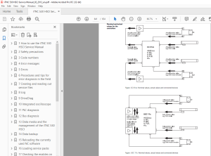
1 Annex: Principle of function of the iTNC 530 HSCI control 641
11 Introduction 641
12 The control loop 641
13 The HSCI bus 648
S.M 7/3/2025
More products