$45
Heidenhain iTNC 530 Service Manual 2006 - PDF DOWNLOAD
Heidenhain iTNC 530 Service Manual 2006 - PDF DOWNLOAD
FILE DETAILS:
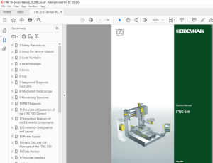
Heidenhain iTNC 530 Service Manual 2006 - PDF DOWNLOAD
Language :English
Pages :539
Downloadable : Yes
File Type : PDF
IMAGES PREVIEW OF THE MANUAL:
DESCRIPTION:
Heidenhain iTNC 530 Service Manual 2006 - PDF DOWNLOAD
Using the Service Manual
2.1 About this Manual
This service manual will assist service personnel in the diagnosis and correction of errors on TNC-controlled machine tools.
It includes:
Theoretical explanation of functions and their correlations
Details of possible error reasons
Descriptions of error diagnosis
Details of corrective action
The “Overview of Possible Errors” on page 26 often includes references to the descriptions of error diagnosis. You will find these descriptions in the chapters of the Service Manual structured according to topics. The Service Manual does not provide commissioning support! It comprises the service possibilities with the current hardware and software of the control at the editing date of this manual. The service possibilities of your units may differ from the manual. Hardware or software based differences in servicing are indicated in the corresponding descriptions.
This manual is valid for:
- iTNC 530 single-processor with NC software 340420 / 421
- iTNC 530 single-processor with NC software 340422 / 423
- iTNC 530 dual-processor with NC software 340480 / 481
- iTNC 530 single-processor with NC software 340490 / 491
- iTNC 530 dual-processor with NC software 340492 / 493
It must be provided that …
The machine had been working perfectly before the error ocurred.
Only genuine spare parts are used!
TABLE OF CONTENTS:
Heidenhain iTNC 530 Service Manual 2006 - PDF DOWNLOAD
1 Safety Precautions 9
2 Using the Service Manual 11
21 About this Manual 11
22 Further Service Manuals 11
23 Other Documentation: 12
24 Support 12
25 Service Training Seminars 12
26 Safety 12
3 Code Numbers 13
31 Introduction 13
32 Overview 13
33 Notes on Entering the Code Numbers 14
4 Error Messages 17
41 Introduction 17
42 HELP Key 19
43 ERR Key 20
44 CE Key 21
45 List of NC Error Messages 22
5 Errors 23
51 Introduction 23
52 Notes and Tips 23
53 Overview of Possible Errors 26
54 Important Notes on the
Use of HEIDENHAIN Interface Boards in SIMODRIVE System 29
6 Log 35
61 General 35
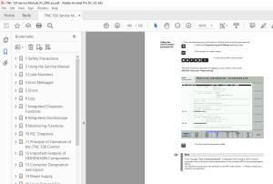
62 Calling the Log 36
63 Overview of Log Entries 37
64 Example of a Log Entry 40
7 Integrated Diagnosis Functions 41
71 Introduction 41
72 Meanings of the Signals under “DSP” 43
73 Electronic ID Label 47
8 Integrated Oscilloscope 49
81 General 49
82 Setup 50
83 Saving and Loading Recordings 53
84 Circular Interpolation Test 54
9 Monitoring Functions 55
91 Introduction 55
92 During Booting 55
93 During Operation 57
931 Position or Servo Lag Monitoring 58
932 Nominal Speed Value 60
933 Movement Monitoring 61
934 Standstill Monitoring 62
935 Positioning Window 62
936 Monitoring of the Power Supply Unit 64
937 Temperature Monitoring 65
938 I2t Monitoring 66
Contents
HEIDENHAIN Service Manual iTNC 530
939 Current Utilization of the Drive Motors 67
9310 Status of HEIDENHAIN Inverters 68
9311 Control of Motor Brakes 70
9312 EMERGENCY STOP Monitoring During Operation 72
10 PLC Diagnosis 73
101 General 73
102 Service Diagnosis in PLC Mode 76
1021 The TABLE Function 76
1022 The LOGIC Diagram 82
1023 The TRACE Function 84
1024 The WATCH LIST Function 85
1025 The I/O-FORCE LIST 87
103 The COMPILE Function 89
104 Calling the PLC Error Table for Diagnosis 91
105 Nonvolatile PLC Markers and Words 93
106 Overviews 95
107 Specifications 106
1071 PLC Inputs 106
1072 Analog Inputs 107
1073 Inputs for Thermistors 107
1074 PLC Outputs 108
11 Principle of Operation of the iTNC 530 Control 109
111 Introduction 109
112 Block Diagrams with Short Explanations 109
113 Basic Circuit Diagrams 116
114 Exchange Possibilities of the iTNC 530 118
12 Important Features of HEIDENHAIN Components 119
121 HEIDENHAIN Components in a Machine Tool 119
122 Hardware Identification 120
123 Display of System Information 130
13 Connector Designation and Layout 135
131 Important Note 135
132 MC and CC 135
1321 Designation and Position of Connectors 135
1322 Pin Layouts on the MC and CC 142
133 Power Supply Units 173
1331 UV 105 Power Supply Unit 174
1332 UV 105 B Power Supply Unit 176
1333 UV 106 (B) Power Supply Unit 178
134 Inverters and Motors 179
135 Interface boards for the SIMODRIVE system 611D 179
136 Encoders 180
1361 Position encoders 180
1362 Speed encoders 182
137 Touch Probe Systems 182
138 Handwheels 183
1381 HR 4xx Portable Handwheel 183
1382 HR 130 Panel-Mounted Handwheel 185
1383 HRA 110 Handwheel Adapter 185
139 PLC Input/Output Units 187
1391 Designation and Position of Connectors 187
1392 PL 4xxB Pin Layouts 190
1393 Pin Layout PL 510 195
1310 Machine Operating Panel 199
July 2002 HEIDENHAIN Service Manual iTNC 530
13101 Designation and Position of Connectors on MB 420 199
13102 Pin Layouts on MB 420 199
1311 iTNC Keyboard 200
13111 Designation and Position of Connectors 200
13112 Pin layouts 201
1312 Visual Display Units 202
13121 Designation and Position of Connectors 202
13122 Pin layouts 203
1313 BTS 1x0 Monitor/Keyboard Switch 204
14 Power Supply 205
141 Power Supply for the iTNC 530 205
1411 General 205
1412 UV 105, UV 105 B 210
1413 UV 106, UV 106 B 214
142 Power Supply for Control-Is-Ready Signal 216
143 Buffer Battery 217
144 Info menu 220
145 Power Supply for the Display Units 221
146 Power Supply for PLC Outputs 222
1461 General 222
1462 Supply Voltage for PLC Outputs on the MC 223
1463 Supply Voltage for PLC Outputs on the PL 4xx B 225
1464 Supply Voltage for PLC Outputs on the PL 510 228
15 Hard Disk and File Manager of the iTNC 530 231
151 Introduction 231
152 Structure of the Hard Disk 232
153 Hard Disk Test 233
154 Setting the System Time 237
155 File Management of TNC Partition (TNC:\) 239
156 File Management PLC Partition (PLC:\) 241
16 Data Backup 245
161 Introduction 245
162 Connection Setup 247
1621 Via Ethernet 247
1622 Via Serial Interface RS 232/V24 or RS 422/V11 256
163 Reading In and Out of Individual Files or Directories 258
164 Backup 261
165 Extracting files from the backup file 265
166 Restore 266
167 Data Interface Operating Modes 269
1671 Overview of operating modes 269
1672 Interface configuration and assignment of mode 270
168 Drive Symbols 271
169 Cable overview 272
1691 Ethernet Interface RJ45 Connection 272
1692 RS-232-C/V24 273
1693 RS-422/V11 278
17 Encoder Interface 279
171 Position encoders 279
1711 Introduction 279
1712 Possible Causes of Error 280
1713 Service diagnosis 281
HEIDENHAIN Service Manual iTNC 530
1714 Additional Diagnosis Possibility on Encoders with EnDat Interface 283
1715 Corrective action 283
1716 Re-Setting the Machine Datum 284
172 Speed encoders 286
1721 Introduction 286
1722 Possible Causes of Error 287
1723 Trouble Shooting on the CC 422 287
1724 Trouble Shooting on CC the 422 289
1725 Additional Diagnosis Possibility on Encoders with EnDat Interface 292
1726 Corrective action 292
1727 Resetting the Spindle Orientation 293
173 Error Code for Encoders with EnDat Interface 294
174 Checking position and speed encoders 295
175 Position Measurement with the Motor Encoder 296
18 Referencing 301
181 Definition 301
182 Traversing the Reference Marks 302
183 Deselect Referencing for Axes 309
19 Checking the Enables on the iTNC 311
191 General 311
192 Examination 313
1921 Examination of the output Control-is-ready (X41/pin34) and input Control-is-ready
signal acknowledgement I3 (X42/pin 4) 314
1922 Checking the global drive enable I32, connector X42 / pin 33 319
1923 Checking the drive enabling for the axis groups via connector
X150 and X151 (if wired) 321
1924 Checking the readiness of the inverter system 322
1925 Überprüfung von PLC-Modulen, Merkern und WörternChecking PLC
modules, markers and words 325
20 Interface to the Drives 327
201 Digital Drives 327
2011 Introduction 327
2012 Possible Causes of Errors 328
2013 Trouble Shooting: Exchanging PWM Outputs on the CC 422 329
2014 Trouble Shooting: Exchanging PWM Outputs on the CC 424 333
2015 Trouble Shooting: Exchanging Power Modules or Output Stages of the
Same Type 337
2016 Trouble Shooting: Exchanging the HEIDENHAIN Interface Boards for
the SIMODRIVE 611 System 340
202 Analog Drives 341
2021 Introduction 341
2022 Possible Causes of Errors 341
2023 Testing the analog nominal speed value interface 341
2024 Adjusting the Electrical Offset (Drift Adjustment) 346
2025 Speed Adjustment at Servo Amplifier (Tachometer Adjustment) 349
203 Switching the Position Display for Service Purposes 351
21 Visual Display Unit 353
211 General 353
212 Possible Causes of Errors 353
213 Fault diagnosis 354
22 Keyboard Unit 357
221 General 357
222 Front View of the Keyboard Units 357
223 Possible Causes of Error 359
July 2002 HEIDENHAIN Service Manual iTNC 530
224 Checking the Keys 360
225 Checking the Potentiometers 364
226 Checking the Mouse Pad 366
227 Key Matrix of the Keyboard Units 367
228 Key Matrix of the Keyboard Units 382
23 Machine Operating Panel 385
231 General 385
232 Checking the Power Supply 386
233 Checking the Keys 387
234 Checking the Outputs 389
24 Handwheel 391
241 General information 391
242 HR 420 Portable Handwheel with Display 393
2421 Checking the Keys 393
2422 Checking the Potentiometers 393
243 HR 410 Portable Handwheel 396
2431 Checking the Keys 396
244 HR 150 Panel-Mounted Handwheels with HRA 110 Handwheel Adapter 398
2441 Checking the Switch 398
25 Touch Probe 401
251 General information 401
252 Touch Trigger Probe with Cable Connection for Workpiece Setup and
Measurement 403
253 Touch Trigger Probe with Infrared Transmission for Workpiece Setup
and Measuring 405
254 Triggering Touch Probe for Tool Measurement 408
26 Exchange of HEIDENHAIN Components 411
261 Important Information 411
262 Exchanging the MC 422 418
263 Removing the Drive Assembly 425
264 Exchanging the MC 422 B or the MC 420 431
265 Exchanging the HDR 433
266 Exchanging the CC 441
267 Exchange of Further HEIDENHAIN Components 442
27 Loading of Service Packs 443
271 Introduction 443
272 Preparations and Execution up to NC Software 34049x-01
(Single and Dual-Processor Version) 444
273 Preparations and Execution as of NC Software 34049x-02
(Single-Processor Version) 446
274 Preparations and Execution as of NC Software 34049x-02
(Dual-Processor Version) 449
275 Service Packs on the Control's Hard Disk 452
28 Activating the NC Software Used on the Machine 453
281 Introduction 453
282 Execution 453
29 Inspection, Measuring and Test Equipment 455
291 Important notes 455
292 Test Adapter, ID 375830-01 456
293 Universal Measuring Adapter, ID 255480-01 460
294 Encoder Diagnostic Set PWM 9, ID 512134-01 461
295 Mounting Help PWT 10/17/18 463
296 IK 215 Adjustment and Testing Kit, ID 547858-01 464
HEIDENHAIN Service Manual iTNC 530
30 Machine Parameters 465
301 What is a Machine Parameter? 465
302 The Machine Parameter Editor 465
303 Meaning of the Machine Parameters 473
304 List of Machine Parameters
(excerpt from the Technical Manual of iTNC 530 of November 2005) 474
3041 Encoders and Machines 474
3042 Positioning 480
3043 Operation with velocity feedforward control 484
3044 Operation with following error (servo lag) 485
3045 Integrated speed and current control 486
3046 Spindle 495
3047 Integral PLC 498
3048 Configuration of the Data Interface 501
3049 3-D touch probe 503
30410 Tool Measurement with TT 505
30411 Tapping 509
30412 Display and Operation 510
30413 Color 517
30414 Machining and program run 520
30415 Hardware 527
30416 Second spindle 534
S.M 7/3/2025
More products