$45
Heidenhain iTNC 530 Service Manual 2010 - PDF DOWNLOAD
Heidenhain iTNC 530 Service Manual 2010 - PDF DOWNLOAD
FILE DETAILS:
Heidenhain iTNC 530 Service Manual 2010 - PDF DOWNLOAD
Language :English
Pages :696
Downloadable : Yes
File Type : PDF
IMAGES PREVIEW OF THE MANUAL:
DESCRIPTION:
Heidenhain iTNC 530 Service Manual 2010 - PDF DOWNLOAD
1 How to Use this Service Manual
1.1 Target Group
This Service Manual has been written for specialist electricians for service, maintenance and
commissioning.
Specialists who perform work on the electrical system of a machine tool and its components
must have the required technical knowledge and competence1.2 About this Manual
This Service Manual assists service personnel in the field in diagnosing and
correcting errors on machine tools controlled by iTNC 530.It includes:
Error messages and types of errors that indicate technical defects
Information on possible error causes
Descriptions of error diagnosis
Application descriptions of the diagnosis tools
Information on corrective action
Data backup instructions
Theoretical explanations of functions and their correlations
TABLE OF CONTENTS:
Heidenhain iTNC 530 Service Manual 2010 - PDF DOWNLOAD
1 How to Use this Service Manual 11
11 Target Group 11
12 About this Manual 11
Udpate service 12
13 Other Service Manuals 12
14 Other Documentation 12
15 Support 12
16 Service Training 12
17 Meaning of the Symbols Used in this Manual 13
18 Safety 13
2 Safety Precautions 15
21 Overview 15
Ground 15
Zero potential 15
Fundamental knowledge 15
Know-how and competence 15
Suitable tools 15
Safety precautions of the machine manufacturer 15
Regulations for power installations and instructions for safety and prevent- ion of accidents 15
Basic insulation 16
Vertical axes 16
Changes to entry values 16
Liability 16
3 Code Numbers 17
31 Introduction 17
32 Overview 17
33 Input of Code Numbers 18
Additional notes 19
4 Error Messages 21
41 Introduction 21
Type of error message 21
Display of the error message 22
Reaction of control and machine 24
Automatic generation of service files 24
42 HELP Key 25
43 ERR Key 26
44 CE Key 28
45 List of NC Error Messages 29
Complete list 29
Filtered list 29
5 Errors Patterns 55
51 Introduction 55
Static and nonstatic errors 55
Sporadic and nonsporadic errors 55
52 Overview of Possible Error Patterns 55
6 Procedures and Tips for Error Diagnosis 59
61 Introduction 59
62 Power Off and On 59
63 Sequence for Finding Serious Electrical Errors 60
Flowchart 61
64 Sequence for Finding Errors in the Control Loop 62
Integrated oscilloscope 62
Flowchart 63
Possible effects of contaminated, loose, defective encoders 64
65 Error Localization by Process of Interchange 65
Example: Interchange possibilities on iTNC 530 65
66 Error Localization by Process of Exclusion 66
Flowchart 67
67 Finding Position Differences of Direct and Indirect Encoder 68
Prerequisite 68
Integrated oscilloscope 68
Conclusion 69
68 Error Localization by Switching from Direct to Indirect Position Measurement 70
Prerequisite 70
Direct position measurement 70
Indirect position measurement 71
Flowchart 71
Conclusion 71
69 Notes and Tips 72
What is the cause of this error? 72
First steps 72
Visual inspection 72
Comparison with functioning machines or devices 72
Low voltages and polyfuses 73
Cables 73
Connectors and females 73
Terminals 73
Shielding and grounding 73
Sources of interference 74
Contamination 74
Temperature 75
Humidity 75
Shipping brace of the hard disk 75
7 Creating and Downloading of Service Files 77
71 Introduction 77
72 Automatic Generation of Service Files 78
73 Manual Generation of Service Files 78
74 Downloading of Service Files 79
8 Log 81
81 Introduction 81
82 Calling the Log 82
83 Overview of Log Entries 83
Entry of IP addresses 85
Entry of operating system error messages 85
Entry of NC programs 86
84 Log Entries at Program Cancelation 87
Considering the tool length 88
Calculating the REF position 88
9 Integrated Diagnostic Functions and DriveDiag 89
91 Introduction 89
92 Activation and Operation 90
Calling the drive diagnosis 90
Selecting the supply device 91
Operating the drive diagnosis 92
Calling the drive information 94
Calling DriveDiag 96
How to operate DriveDiag 97
93 For Error Diagnosis 98
10 Integrated Oscilloscope 99
101 Introduction 99
102 Activation and Settings100
Mode of operation101
Sample time101
Output102
Feed rate102
Channel 1 to 6102
Signals102
Trigger104
Trigger threshold104
Edge104
Pre-trigger104
103 Recording and Adjusting the Signals105
Vertical resolution105
Horizontal resolution107
Other soft keys108
Cursor information108
Specific for pre-triggering109
104 Saving and Loading Recordings110
105 For Error Diagnosis111
1051 Triggering on error marker111
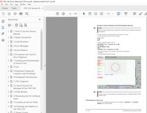
1052 Circular interpolation test113
1053 Descriptions in this manual114
11 PLC Diagnosis115
111 Introduction115
Definition of PLC115
Tasks of the PLC115
Data exchange with the PLC115
PLC error messages115
Calling the PLC mode115
PLC main page116
PLC functions of the main menu117
112 Possible Causes of Errors118
General information118
Additionally for the use of PROFIBUS118
113 Diagnosis Tools in the PLC Mode119
1131 The TABLE function119
Call119
Checking the PLC inputs120
Conclusion121
Error localization PLC input122
Checking the PLC outputs123
Conclusion123
Meaning of the LEDs on the PLD 16-8123
Measuring circuit with test adapter for PLC inputs and outputs on the MC124
1132 The LOGIC diagram125
Call125
Selecting the operands125
Start of recording126
Saving the LOGIC DIAGRAM recording127
Calling the LOGIC DIAGRAM recording127
Further possibilities with the integrated oscilloscope127
1133 The TRACE function128
Call128
Selecting the PLC128
Evaluation128
1134 The WATCH LIST function129
Call129
Selecting symbolic operands in the WATCH LIST129
Selecting absolute operands in the WATCH LIST130
Saving the WATCH LIST file130
Calling a WATCH LIST file130
1135 The I / O - FORCE LIST131
Call131
Selecting inputs and outputs for the FORCE LIST131
Activating the I/O FORCE LIST132
Saving the I/O FORCE LIST file132
Calling an I/O FORCE LIST file132
Deactivating and exiting the I/O FORCE LIST132
1136 PROFIBUS diagnosis133
Call133
Soft keys for the PROFIBUS diagnosis134
Use for troubleshooting134
Log files135
114 Non-Volatile PLC Markers and Words136
Saving on hard disk136
Playing back the data into the RAM137
115 Overviews138
Overview of markers138
Overview of words144
Overview of operands146
116 Specifications147
1161 PLC inputs147
1162 Analog inputs148
1163 Inputs for thermistors148
1164 PLC outputs149
Output signals and addresses149
Supply voltage for PLC outputs149
12 Hard Disk and File Manager of the iTNC 530151
121 Introduction151
HDR and drive assembly151
122 Structure of the Hard Disk152
Single-processor control152
Dual-processor control152
123 Possible Causes of Error152
124 Test of Hard Disk153
No communication with the hard disk153
Communication with the hard disk153
With the single- processor control (without Windows)154
With the dual- processor control (with Windows)157
125 Setting the System Time159
With the single- processor control159
With the dual- processor control control161
126 Setting the Program Manager162
127 File Management of TNC Partition163
Calling the TNC partition163
Using the mouse163
Overview of the most important TNC file types164
Which file type is to be listed?164
File information164
128 File Management of PLC Partition165
Calling the PLC partition165
Using the mouse166
Overview of the most important PLCfile types166
Which file type is to be listed?167
File information167
13 Data Backup169
131 Introduction169
Backup recommended169
Data backup169
Available data interfaces169
Windows knowledge170
Authorization170
TNCremoNT data transfer software170
BINARY-to-ASCII conversion170
Protection from data tampering171
132 Connection Setup172
1321 Via Ethernet172
Requirements172
Management of the Ethernet interface on the iTNC 530172
Connection via your local network172
Connection establishment at the customer's (field service)172
Adjusting Ethernet settings on the laptop173
Adjusting Ethernet settings on the control175
TNCremoNT179
„Pinging"180
Meaning of the LEDs on the Ethernet data interface X26181
Restoring original settings181
1322 Via serial interface RS-232-C or RS-422182
Requirements182
Managing the serial data interfaces on the iTNC 530182
Connection setup182
Configuration of the serial interface on the iTNC183
TNCremoNT183
1323 Via USB185
Requirements185
Connecting the USB stick185
Disconnecting the USB stick185
133 Reading In and Out of Individual Files or Directories186
Connection setup186
Transferring data to the USB flash drive186
Transferring data from the USB flash drive188
Reading out data using TNCremoNT190
Reading in data using TNCremoNT191
134 Backup on an External Data Medium192
Connection setup192
Selecting the target drive on the laptop192
Creating target folder on laptop192
Selecting the control partition192
Call the back-up function193
Selecting the backup type193
Starting the backup194
135 Extracting Files from the Backup File196
136 Restoring Data197
Connection setup197
Backup file197
Starting the restoring procedure198
137 Cable Overview200
1371 Ethernet interface RJ45 connection200
1372 RS-232-C (V24)201
Accessories202
1373 RS-422 (V11)204
138 Operating Modes of the Data Interfaces205
1381 Overview of operating modes205
FE1205
EXT 1, EXT 2205
LSV-2:205
1382 Interface configuration and assignment of mode206
Calling the interface setup206
Operating mode / baud rate206
139 Drive Symbols207
14 Reloading the NC Software Used209
141 Introduction209
142 Preparations209
Test of Hard Disk209
Active NC software version and service pack209
Preparing the machine209
143 Proceeding up to NC Software 34049x-01 (Single-Processor Version)210
144 Proceeding as of NC Software 34049x-02 (Single-Processor Version)212
145 Proceeding for the Dual-Processor Version215
15 Loading of Service Packs219
151 Introduction219
Display on the screen219
152 Preparations220
Who provides the new Service Pack?220
Preparing the machine220
153 Execution up to NC Software 34049x-01 (Single and Dual Processor Version)221
Unzipping the ZIP File221
Access to the service pack files via the customer network221
Transferring files service packs from the laptop to the control221
Loading the service pack221
Functional test222
154 Execution as of NC Software 34049x-02 (Single-Processor Version)223
Unzipping the ZIP File223
Access to the service pack files via the customer network223
Loading the service pack223
Functional test225
155 Execution as of NC Software 34049x-02 (Dual-Processor Version)226
Unzipping the ZIP File226
Access to the service pack files via the customer network226
Loading the service pack226
Functional test228
16 Checking the Enables on the iTNC 530229
161 Introduction229
Closed EMERGENCY-STOP chain229
Acknowledgment control is ready230
Global drive enabling230
Drive enabling for axis groups230
Drives ready for operation230
Current and speed controller active231
Some machine parameters231
162 Examination232
Selecting the supply device232
1621 Checking the "Control is ready" output and input (EMERGENCY STOP chain)233
Fault: Message "Relay external DC voltage missing" permanently displayed233
Page from the integrated drive diagnosis234
Page from DriveDiag234
Excerpt from the basic circuit diagram235
Sliding switch on I/O module235
Error message: EMERGENCY STOP defective236
Bridge inserted238
1622 Checking the global drive enable I32, connector X42 / pin 33239
Page from the integrated drive diagnosis240
Page from DriveDiag240
Excerpt from the basic circuit diagram241
1623 Checking the drive enabling for the axis groups via connector X150 and X151 (if wired)242
Page from the integrated drive diagnosis242
Page from DriveDiag242
1624 Checking the readiness of the inverter system243
Pages from the integrated drive diagnosis243
Page from DriveDiag244
Page from the integrated drive diagnosis244
Page from DriveDiag245
Green READY LEDs on the drives245
Red LED SH1247
Red LED SH2247
1625 Checking PLC modules, markers and words248
17 Power Supply251
171 Power Supply for the iTNC 530251
1711 Introduction251
Power supply by UV 105252
Power supply by UVR253
Power supply by UV 105 B254
Power supply by UV 106 (B)255
1712 UV 105, UV 105 B256
Possible causes of error256
Troubleshooting UV 105 (B)256
Control of the LED READY UV256
5 V on auxiliary terminal256
Function of the fan256
Checking the supply voltages256
Uz of a non HEIDENHAIN inverter system257
Fuses in UV 105 (B)258
Corrective action259
Mounting the UV 105 (B)259
1713 UV 106, UV 106 B260
Possible causes of error260
Troubleshooting UV 106 (B)260
Control of the LED READY UV260
Function of the fan260
Checking the supply voltages260
Fuses in UV 106 (B)261
Corrective action261
Mounting the UV 106 (B)261
172 Power Supply for "Control-Is-Ready Signal"262
X34: Power supply for "Control-Is-Ready" signal output262
Error messages262
Troubleshooting263
173 Buffer Battery264
Introduction264
Message264
Checking the charge status of the "Gold cap"265
Replacing the buffer battery265
Position of the buffer battery265
Were any data lost?266
174 Information Menu267
Call267
Description267
175 Power Supply for PLC Outputs268
1751 Introduction268
Power consumption268
Nominal operating current per output268
1752 Supply voltage for PLC outputs on the MC269
X44: PLC supply voltage269
Error message269
Troubleshooting X44270
Fine wire fuses271
1753 Supply voltage for PLC outputs on the PL 4xx B272
Connection272
X9 to X14: Power supply272
X23: Supply voltage of the analog inputs of the PL 410 B273
Error273
Functional check273
1754 Supply voltage for PLC outputs on the PL 510274
Connection274
PLB 510 basic module274
PLD 16-8 input/ output module274
LED display275
Error275
Functional check275
176 Power Supply for the Display Units276
Errors276
Troubleshooting276
18 Encoder Interface277
181 Position Encoders277
1811 Introduction277
Position encoder inputs277
Monitoring of the position encoders277
Assignment of the position encoders278
EnDat encoders278
Memory areas in the EnDat encoder278
Signal type and input frequency278
Polyfuses278
1812 Possible causes of errors279
1813 Troubleshooting280
Example280
Example machine parameters280
Block diagram280
Flowchart281
1814 Possibilities with the integrated diagnosis or DriveDiag282
EnDat position encoder282
Position encoder test282
1815 Possibilities with the integrated oscilloscope283
1816 Corrective action286
Encoder components286
Control286
1817 Determining the field angle on linear motors, torque motors and synchronous spindles287
1818 Resetting the machine datum288
Individual axis288
Gantry axes with two position encoders290
1819 Restoring the spindle orientation292
182 Speed Encoders293
1821 Introduction293
Speed encoder inputs293
Monitoring of rotary encoders293
Assignment of speed encoders293
EnDat encoders294
Memory areas in the EnDat encoder294
Temperature sensor lines294
Polyfuses294
Different servicing294
1822 Possible causes of errors295
1823 Trouble shooting on the CC 422296
Example296
Example machine parameters296
Block diagram296
Flowchart297
1824 Trouble shooting on the CC 424 (B)298
Example298
Example machine parameters298
Notes and preliminary action298
Block diagram298
Flowchart299
1825 Possibilities with the integrated diagnosis or DriveDiag300
1826 Possibilities with the integrated oscilloscope301
1827 Corrective action304
Motor encoder in a synchronous motor304
Motor encoder in an asynchronous motor304
Control304
1828 Readjusting the trip dog for reference end position305
1829 Resetting the machine datum306
18210 Restoring the spindle orientation306
183 Error Codes for Encoders with EnDat Interface307
184 Further Examination of Position and Speed Encoders308
Introduction308
PWM 9308
PWT309
IK 215310
185 Position Measurement via Motor Encoder (Indirect Position Measurement)311
Note!311
Preliminary action312
Line count of the motor encoder312
Flowchart for individual axis313
Flowchart for axes with master-slave torque control314
186 Switching over the Position Display for Servicing315
Call315
Description of the settings315
19 Reference Run317
191 Definition317
Reference marks317
Machine datum317
Distance between the scale reference point and the machinedatum317
Spindle preset317
192 Traversing the Reference Marks318
193 Possible Causes of Errors318
194 Troubleshooting319
Examining the encoders319
Examining the reference mark319
Examining the switch signal of the trip dog319
195 Corrective Action320
196 Deselecting the Reference Run for Axes320
197 Retraction after an Error with Control Reset321
General information321
Tilted axes321
20 Interface to the Drives323
201 Digital PWM Interface323
2011 Introduction323
PWM outputs323
Assignment of the PWM outputs323
PWM frequency324
Single and double- speed control loops325
Power supply modules, power stages and motors325
Different servicing325
2012 Tables for power supply modules, power stages and motors326
Table of power supply modules326
Power module table328
Motor table330
2013 Possible causes of error332
2014 Sequence for finding errors in the control loop332
2015 Troubleshooting: Interchanging PWM outputs on the CC 422333
Modular setup with CC 422333
Example333
Example machine parameters333
Notes and preliminary action333
Block diagram334
Flowchart335
Next test335
2016 Troubleshooting: Interchanging PWM outputs on the CC 424 (B)336
Modular setup with CC 424 (B)336
Example336
Example machine parameters336
Notes and preliminary action336
Block diagram337
Flowchart338
Next test338
2017 Troubleshooting: Interchanging power modules or output stages of the same type339
Assumed configuration for two 1-axis modules340
Assumed configuration for one 2-axis module340
Example340
Block diagram for two 1-axis modules340
Flowchart for two 1-axis modules341
2018 Troubleshooting: Interchanging the HEIDENHAIN interface boards for the SIMODRIVE 611 system342
Boards of the same type342
Boards of different types342
2019 Corrective action343
Control343
Drive components343
Mechanics343
202 Analog Speed Command Interface344
2021 Introduction344
Analog speed value outputs344
Assignment of the speed value outputs344
2022 Possible causes of error344
2023 Sequence for finding errors in the control loop345
2024 Checking the analog speed command interface346
Observation with the integrated oscilloscope346
Error: No axis movement!346
Flowchart347
Battery box348
Measuring setup with test adapter348
Specifications of the analog channels348
2025 Adjusting the electrical offset (drift adjustment)349
Offset adjustment at the analog servo amplifier349
Offset fine adjustment in the control351
2026 Speed adjustment at the servo amplifier (tachometer adjustment)352
Suggestion how to perform the adjustment352
Comparison of noml and actl speed in the integrated oscilloscope353
2027 Corrective action354
Control354
Drive components354
Mechanics354
21 Visual Display Unit355
211 Introduction355
212 Possible Causes of Errors355
213 Troubleshooting356
VDU soft keys356
Monitor356
Rear view BF 150357
Rear view BF 120358
214 Corrective Action358
VDU soft keys358
Fan358
Front glass358
Monitor358
Control358
22 Keyboard Unit359
221 Introduction359
222 Front View of the Keyboard Units360
223 Possible Causes of Error362
224 Checking the Keys363
Correct operation?363
Visual inspection363
Does the control receive the key signal?363
Principle of the key matrix364
Flowchart364
Measuring setup with test adapter365
Test adapter replaces keyboard366
225 Checking the Potentiometers367
Potentiometer values in the PLC-TABLE367
Potentiometer values in the integrated oscilloscope367
Measuring setup with test adapter369
226 Checking the Touchpads370
Second USB interfaces370
Other mouse370
Touchpad on laptop370
227 Corrective Action371
Pushbuttons371
Potentiometer371
Control371
228 Key Matrix of the Keyboard Units372
TE 520 B TE 530 TE 530 B TE 535 Q372
TE 420383
229 Key Matrix of the Visual Units388
BF 150388
BF120 BF 150388
23 Machine Operating Panel389
231 Introduction389
232 Possible Causes of Errors390
233 Checking the Power Supply391
Measuring setup with test adapter391
234 Checking the Keys392
Correct operation?392
Visual inspection392
Does the control receive the key signal?392
Measuring setup with test adapter395
Test adapter replaces MB396
235 Checking the Outputs397
236 Corrective Action398
Pushbuttons398
Other MB components398
Control398
24 Handwheel399
241 Introduction399
242 Possible Causes of Errors400
243 Error Location on Portable Handwheel with HR 420 Display401
Control impaired?401
Visual inspection401
Functional check401
Power supply OK?401
Checking the keys403
Checking the potentiometers404
244 Error Diagnosis at HR 410 Portable Handwheel406
Control impaired?406
Visual inspection406
Functional check406
Power supply OK?406
Checking the keys408
245 Deselecting and Disconnecting the Portable Handwheel409
Dummy plug409
246 Error Diagnosis at Panel-Mounted Handwheels410
Power supply OK?410
Checking the switches411
Assignment of the switch positions to the PLC inputs411
247 Corrective Action412
Keys412
Cables and handwheel adapters412
Control412
25 Touch Probe413
251 Introduction413
Different touch probes413
Infrared transmission415
Touch probe cycles416
Pin layout416
Other information416
252 Possible Causes of Errors417
253 Error Diagnosis on TS Touch Probes418
Control impaired?418
Visual inspection418
Checking the LEDs418
Checking the "Ready" bridge419
Functional test420
254 Error Diagnosis on TT Touch Probes422
Control impaired?422
Visual inspection422
Checking the LEDs422
Checking the "Ready" bridge422
Functional test423
255 Error Diagnosis on Laser Touch Probe425
Control impaired?425
Visual inspection425
Checking the LEDs425
Checking the "Ready" bridge425
256 Deselecting and Disconnecting the Touch Probe426
257 Corrective Action427
Cleaning427
Readjusting the SE427
Exchange of components427
Recalibration427
Returning the touch probe427
Returning the control427
26 Important Features of HEIDENHAIN Components429
261 HEIDENHAIN Components in a Machine Tool429
262 Hardware Identification430
ID label430
Main computer430
HDR hard disk, SIK431
Controller units431
Power supply units432
Visual display units433
Keyboards434
Switching unit435
Machine operating panel435
Handwheels436
Touch probes438
PLC Expansion440
Encoders442
Inverters and motors442
Interface boards for the SIMODRIVE system 611D442
263 Display of Important System Information443
Calling the display443
Display for NC software 340420-xx to 340480-xx443
NC software443
PLC software444
Preset table444
Options444
DSP software444
Current controller software445
Display for NC Software as of 340490-xx (smarTNC programming interface)445
Feature Content Level445
27 Connector Designation and Layout447
271 Important Note447
272 MC and CC447
2721 Designation and position of connectors447
2722 Pin Layouts on the MC and CC457
X1 to X6, X35 to X38, X201 to X214: Position encoder 1 VPP457
X1 to X6, X35 to X38, X201 to X214: Position encoders with EnDat interface458
X8: Analog output 1 to 6459
X9: Analog output 7 to 13459
X12: Connection of the touch probe for workpiece measurement460
X13: Connection of the touch probe for tool measurement462
X15 to X20, X80 to X87: Speed encoder 1 VPP463
X15 to X20, X80 to X87: Speed encoder with EnDat interface464
X23: Handwheel input467
X26: Ethernet interface RJ45 connection467
X27: RS-232-C/V24 data interface468
X28: RS-422/V11 Data interface469
X30: Reference signal spindle469
X34: Power supply for “Control is ready”469
X41: PLC outputs on the MC 42x (B/C)470
X42: PLC inputs on the MC 42x (B/C)471
X44: PLC supply voltage472
X45: iTNC control panel473
X46: Machine operating panel474
X47: PLC expansion for PL 4xx B on the MC 422 (B/C)475
X47: PLC expansion for PL 510 to the MC 422 (B/C)476
X48: Analog input (PLC) on the MC 42x (B/C)477
X49: BF 120 flat-panel display478
X51 to X64: PWM-output480
X69: NC power supply and control signals481
X74: 5 V supply481
X127: RS-232-C/V24 data interface482
X128: RS-422/V11 data interface483
X141, X142: USB connection483
USB hub483
X147: PLC Expansion for PL 510 on the MC 420484
X149: BF 150 flat-panel display485
X150, X151: Drive controller enable for axis groups486
X169: NC supply voltage and control signals486
273 Power Supply Units487
2731 UV 105 power supply unit488
Connection overview UV 105488
X31: Power supply unit for UV 105489
Power supply of the UV 105 with UZ489
X69: NC supply voltage and control signals489
X74: 5 V connection of the UV 105489
2732 UV 105 B power supply unit490
Connection overview UV 105 B490
Connector on the front panel491
50-pin ribbon cable491
5V terminal on the front panel491
2733 UV 106 (B) power supply unit492
Connection overview UV 106 (B)492
X31: Power supply of the UV 106 (B)492
274 Monitors493
2741 Designation and position of connectors493
BF 120493
BF 150493
2742 Pin layouts494
X1: Power supply494
X2: Connection of the BF 120 to the MC494
X2: Connection of the BF 150 to the MC494
X3: Connection of the VDU soft keys to the iTNC operating panel494
275 Keyboard Units495
2751 Designation and position of connectors495
TE 420495
TE 520 B495
TE 530 (B)496
TE 535 Q496
2752 Pin layouts497
X1: Connection of the VDU soft keys to the iTNC operating panel497
X2: iTNC keyboard497
X9: USB interface for the mousepad497
276 BTS 1x0 Monitor/Keyboard Switch498
X1, X2, X4, X5 to X7: Monitor and keyboard connections498
X3: Switchover between the keyboards498
X8: Supply voltage for BTS 1x0498
277 Machine Operating Panel499
2771 Designation and position of connectors499
MB 420499
MB 520499
2772 Pin Layouts on MB 420499
X1: Connection to MC499
X2: Connection of NC start and NC stop key499
X3: PLC Inputs499
X4: PLC outputs500
2773 Pin layouts on MB 520500
X3: Connection to MC500
X10: To a transfer unit501
X11: Vacant PLC inputs501
X12: PLC outputs502
X13, X14, X15: Key connections502
278 Handwheels503
X23: Handwheel input503
2781 HR 4xx portable handwheel503
2782 HR 130 panel-mounted handwheel504
2783 HRA 110 handwheel adapter505
X1 to X3: Inputs on the HRA 110 for the HR 150 handwheels505
X23: Connection to MC 42x (B/C)506
X31: HRA 110 supply voltage506
279 Touch Probes507
Touch probes for workpiece measurement507
Touch probe for tool measurement507
2710 PLC Input/Output Units507
27101 Designation and position of connectors507
PL 405 B507
PL 410 B508
PL 510509
27102 PL 4xxB Pin Layouts510
X1: PLC expansion on the MC510
X2: PLC expansion PL 4xx B on the PL 410 B510
X3: PLC input PL 410 B and PL 405 B511
X4: PLC input PL 410 B and PL 405 B511
X5: PLC input PL 410 B512
X6: PLC input PL 410 B512
X7: PLC output PL 410 B513
X8: PLC output PL 410 B and PL 405 B513
X9 to X14: Power supply514
X15 to X18: Analog input on the PL 410 B514
X19 to X22: Connection for Pt 100 on the PL 410 B514
X23: Supply voltage for analog inputs of the PL 410 B515
27103 Pin layouts for PL 510516
X1: PLC expansion on the MC 422 (B)516
X1: PLC expansion on the MC 420516
X2: PLC expansion PL 510 on the PL 510516
X3: Supply voltage for logic516
X4 to X5: PLC inputs on the PL 510517
X6: PLC outputs on the PL 510518
X6: Power supply for the PLC outputs on PLD 16-8 input/ output module518
X15 to X18: Analog input on the PLA 4-4 analog module519
X19 to X22: Connection for Pt 100 on the PLA 4-4 analog module519
2711 Encoders520
27111 Position encoders520
Adapter connector TTL (HEIDENHAIN)/ 1 VPP521
Adapter connector TTL (SIEMENS) / 1 VPP521
Adapter connector 11 µAPP / 1 VPP522
27112 Speed encoders522
2712 Inverters and Motors522
2713 Interface Boards for the SIMODRIVE System 611D522
28 Exchange of HEIDENHAIN Components523
281 Important Information523
Which components may be exchanged in the field?523
What could be exchanged in addition?523
NC software update524
Export restrictions524
Windows license524
SIK525
Feature Content Level526
Electronic ID label526
MPNAMEMP527
ESD protection528
Information on possible errors529
ID numbers for service order529
Serial number for traceability529
Replacement units and spare parts530
Repair530
Checking after replacement of electrical components530
282 Exchange of the MC 422531
Preparing the machine531
Backup of non-volatile PLC markers and words531
Data backup531
Removing the Defective MC 422531
Shipping brace of the hard disk532
SIK533
Integrating the New MC 422534
Adapting the MPNAMEMP534
Setting date and time on the new MC 422534
Setting up the data interface534
Defining the NC software version534
Restoring the data535
Updating the machine parameter list535
Reset non-volatile PLC markers and words536
Restoring the original state of the machine536
Functional test536
Creating a machine backup536
Removing the defective MC 422536
283 Exchange of the Drive Assembly537
Preparing the machine537
If possible …537
Removing the defective drive assembly537
Shipping brace of the hard disk538
Integrating the new drive assembly538
Adapting the MPNAMEMP539
Setting date and time on the control539
Setting up the data interface539
Defining the NC software version539
Restoring the data539
Updating the machine parameter list540
If possible …541
Restoring the default settings on the machine541
Functional test541
Creating a machine backup541
Removing the defective drive assembly541
284 Exchange of the MC 422 B, MC 422 C, MC 420542
Preparing the machine542
Backup of Non-Volatile PLC Markers and Words542
Removing the defective MC 422 B (MC 422 C, MC 420)542
Mounting the new MC 422 B (MC 422 C, MC 420)542
Setting date and time on the new MC 422 B (MC 422 C, MC 420)542
Reset non-volatile PLC markers and words542
Restoring the original state of the machine543
Functional test543
Returning the defective MC 422 B (MC 422 C, MC 420)543
285 Exchange of the HDR544
Preparing the machine544
If possible …544
Removing the defective HDR545
Shipping brace of the HDR546
SIK547
Installing the new HDR547
Upgrading the main memory548
Adapting the MPNAMEMP548
Setting date and time on the control548
Setting up the data interface548
Defining the NC software version548
Restoring the data548
Updating the machine parameter list549
If possible …550
Restoring the original state of the machine550
Functional test550
Creating a machine backup550
Returning the defective HDR550
286 Exchange of the CC551
Preparing the machine551
Removing the defective CC551
Mounting the new CC551
Functional test551
Returnings the defective CC551
287 Exchange of the Buffer Battery552
288 Exchange of Other HEIDENHAIN Components553
Encoders553
Drive components and mechanics553
Cables553
Shielding and grounding553
Packaging553
289 Exchange of HEIDENHAIN Components in the SIMODRIVE System554
Version with D-sub connector554
Version with ribbon cable connector558
Compatibility of HEIDENHAIN interface boards and SIMODRIVE power modules559
29 Measuring, Testing and Inspection Equipment561
291 Important Notes561
292 Test Adapter562
Brief description562
Adapter cable to the test adapter563
293 PWM 9 Encoder Diagnostic Set566
Brief description566
Available functions567
294 PWT 10/17/18 Testing Unit568
Short description568
Available functions569
295 IK 215 Adjusting and Testing Package570
30 Machine Parameter571
301 Explanation571
302 The Machine Parameter Editor572
303 Meaning of the Machine Parameters579
304 List of Machine Parameters580
3041 Encoders and machines580
3042 Positioning586
3043 Operation with Velocity Feedforward Control592
3044 Operation with following error (servo lag)593
3045 Integrated speed and current control594
3046 Spindle603
3047 Integrated PLC606
3048 Configuration of the Data Interface609
3049 3-D touch probe611
30410 Tool Measurement with TT613
30411 Tapping616
30412 Display and operation617
30413 Color624
30414 Machining and Program Run627
30415 Hardware634
30416 Second spindle643
1 Annex: Principle of Function of the iTNC 530 Control645
11 Introduction645
12 The Control Loop645
The control loop for analog axes/ spindles645
The control loop for digital axes/ spindles646
Nominal and actual values for the controllers647
Cycle times647
Look ahead647
The interpolator648
The position controller648
Operation with following error648
kv factor during control with following error649
Interrelation of kv factor, feed rate, and following error649
Position control with velocity feedforward control650
Position control with velocity semifeedforward control651
The speed controller652
The current controller652
Double-speed control loops653
13 PWM Signals654
2 Annex: Principle of Function of the iTNC 530 Control657
3 Annex: Monitoring Functions661
31 Introduction661
32 During Start-Up661
EMERGENCY STOP test661
Time diagram662
Possible errors and error messages662
Possible causes of error662
Troubleshooting662
33 During Operation663
331 Position or servo lag monitoring664
Possible causes of error664
Difference between position at switch- on and shutdown664
Possible causes of error665
332 Nominal speed value monitoring666
Problem or error666
Possible remedies666
333 Movement monitoring667
Possible causes of error668
Possible causes of error for movement monitoring … B668
334 Standstill monitoring669
Possible causes of error669
335 Positioning window670
Possible error670
Possible causes of error670
Test for troubleshooting670
Axes in position670
Axes in motion671
336 Monitoring of the power supply unit672
Excessive voltage672
Possible causes of error672
Too low voltages672
Possible causes of error673
337 Temperature monitoring674
Temperature of the MC 42x (B/C)674
Motor temperature674
Heat sink temperature of the power module674
Possible causes of error674
338 Internal power supply and housing fan675
339 I2t monitoring676
General information676
Function676
Basics677
Settings and evaluation678
Limit values678
Machine parameters679
Interrogation through PLC module679
Temperature models679
Compatibility680
Possible causes of error680
3310 Actual utilization of drive motors681
3311 Status of HEIDENHAIN inverters682
Status signals that are already low- active or not available during control start-up682
3312 Controlling the motor brakes684
Automatic test of the motor brakes at switch-on685
3313 EMERGENCY STOP monitoring during operation687
Internal EMERGENCY STOP687
External EMERGENCY STOP via MC (I3)687
External EMERGENCY STOP via CC (axis releases)688
Index689
Contact696
S.M 6/3/2025
More products