$45
Heidenhain MANUALplus 620 Technical Manual - PDF DOWNLOAD
Heidenhain MANUALplus 620 Technical Manual - PDF DOWNLOAD
FILE DETAILS:
Heidenhain MANUALplus 620 Technical Manual - PDF DOWNLOAD
Language :English
Pages :1405
Downloadable : Yes
File Type : PDF
IMAGES PREVIEW OF THE MANUAL:
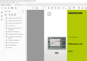
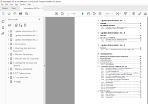
TABLE OF CONTENTS:
Heidenhain MANUALplus 620 Technical Manual - PDF DOWNLOAD
1 Update Information No 1 17
11 Overview 17
12 NC Software 548 328-02 17
121 Important notes on updating software 17
122 Description of the new functions 23
1 Update Information No 2 33
11 Overview 33
12 NC Software 548 328-03 33
121 Important notes on updating software 33
122 Description of the new functions 35
1 Update Information No 3 43
11 Hardware 43
111 UEC 11x controller unit with inverter and PLC I/O 43
2 Introduction 47
21 Meaning of the Symbols Used in this Manual 47
22 Proper Operation 47
23 Trained Personnel 47
24 General Information 48
241 HSCI interface 51
25 Component Overview of MANUALplus 620 52
251 MC main computer, CFR memory card and SIK 52
252 SIK (System Identification Key) 54
253 CC 6106 controller unit 54
254 UEC 11x controller unit with integrated inverter and PLC 55
255 PLC input/output systems with HSCI interface 57
256 PSL 130 low-voltage power supply unit 61
257 MB 620T machine operating panel 63
258 HSCI Adapter for PLB 6001 OEM-Specific Machine Operating Panel 63
259 Handwheels 64
2510 Key symbols 67
2511 Touch probes 71
2512 Other accessories 74
2513 Documentation 74
26 Brief Description 75
261 Specifications of the MANUALplus 620 75
262 User functions 80
263 Software options 85
264 Accessories 86
27 Software 88
271 Designation of the software 88
272 PLC software 89
273 Enabling additional control loops or software options 89
274 Configurations 93
275 Coordinate system of the lathe 93
276 NC software exchange on the MANUALplus 620 94
277 Installing a service pack 100
278 Reversing a software update 101
279 Special features of the software 103
2710 Firmware update on HSCI devices 104
2711 Monitoring hardware changes 106
2712 Data backup 106
28 Software Releases 107
281 NC software 548 328-xx 107
3 Mounting and Electrical Installation 109
31 General Information 109
311 Safety precautions 109
312 Degrees of protection 110
313 Electromagnetic compatibility 110
314 ESD protection 111
32 Environmental Conditions 113
321 Storage and operating temperatures 113
322 Heat generation and cooling 115
323 Limit values for ambient conditions 116
324 Installation elevation 116
325 MC6110T mounting position 117
326 Mounting attitude of CC 61xx, UV xxx, UM xxx, UE 2xx B 118
33 Overview of Components 119
34 HSCI 122
341 Introduction 122
342 Topology 123
343 HSCI interface 124
35 Connection OverviewMANUALplus 620 125
351 MC 6110T main computer 125
352 CC 6106 126
353 CC 6108 127
354 UEC 11x 128
355 PLB 62xx 130
356 PLB 61xx 130
357 I/O modules PLD-H and PLA-H 131
36 Supply Voltages in the HSCI System 133
361 X90: +24 V NC output of the UxC 11x (FS) 135
362 X101: NC power supply 136
363 Power supply of the CC61xx 137
364 PSL 130 low-voltage power supply unit 140
37 UxC 11x (FS): Power Supply and Motor Connection 149
371 UEC 11x (FS) 149
38 UxC 11x (FS): Meaning of the LEDs 155
39 Power supply for PLC outputs 156
310 Power Supply for PLB 6xxx (FS) 157
311 Power supply for control-is-ready signal 157
312 Drive Controller Enable 158
313 Digital PLC Inputs/Outputs 159
3131 UxC 11x (FS): Digital PLC inputs/outputs 164
314 Analog PLC inputs/outputs 169
315 PROFIBUS Connection 171
316 Configuring the PLC Inputs/Outputs with IOconfig 172
317 Buffer battery 173
318 Encoder connections 174
3181 General information 174
3182 Position encoder input 175
3183 Input of speed encoder 177
319 Adapters for Encoder Signals 183
320 Connecting the Motor Power Stages (Only CC 61xx) 187
321 Touch Probe Systems 188
322 Data Interfaces 191
3221 USB interface (USB 20) 194
323 MB 620T Machine Operating Panel 195
324 HSCI Adapter for PLB 6001 OEM-Specific Machine Operating Panel 201
325 Handwheel Input 206
3251 HR 410 portable handwheel 206
3252 HR 130 panel-mounted handwheel 209
3253 HRA 110 handwheel adapter 210
326 CML 110 Capacitor Module 212
327 Connecting Cable: Specifications 213
328 Dimensions 214
3281 MC 6110T 215
3282 MB 620T 216
3283 CC 6106 217
3284 CC 6108 / CC 6110 218
3285 UEC 11x (FS) 219
3286 PL 6xxx (FS) 220
3287 PLB 6001 (FS) 221
3288 PSL 130 222
3289 PSL 135 223
32810 Adapter block for the data interface 224
32811 USB hub 225
32812 Line-drop compensator 226
32813 Handwheels 226
32814 Touch probes 229
32815 CML 110 236
32816 USB hub for operating panel 236
329 HSCI Connection Overview of the MANUALplus 620 with CC 61xx 237
330 HSCI Connection Overview of the MANUALplus 620 with UEC 11x 238
331 Grounding Diagram for MANUALplus 620 with Modular HEIDENHAIN Inverter System 239
332 Basic Circuit Diagram for MANUALplus 620 240
333 Cable Overview for MANUALplus 620 with UEC 11x - Basic Configuration 241
334 Cable Overview for MANUALplus 620 with CC 610x - Basic Configuration 242
335 Cable Overview for HEIDENHAIN Inverter System 243
336 Cable Overview for MANUALplus 620 - Accessories 244
4 Machine Parameters 245
41 General Information 245
42 The “Machine Parameter” Mode of Operation 247
421 Calling the configuration editor 247
422 Entering and changing machine parameters 249
423 Accessing machine parameters via MP numbers 259
424 Managing configuration files 261
425 Sort file content 261
426 Attribute information 262
427 Access protection / options 264
428 Update rules 265
429 Remove syntax error 275
4210 Resets the update version 275
4211 Backup of parameters 276
43 User Parameters 277
431 Configuration of the user parameters 278
432 Example: 284
433 XML commands for creating the layout files 286
44 The KeySynonym Function 289
45 Allocation of Configuration Data 291
46 Structure of a Parameter File 292
47 Machine-Parameter Subfiles 295
471 Syntax of machine parameter subfile 295
472 Activating the machine parameter subfile 295
473 Displaying/editing data records in the configuration editor 298
48 Read or Change Machine Parameters via a PLC Module 300
49 Switching Parameter Sets 306
410 Overview of Machine Parameters 316
4101 "System" Group 316
4102 "Channels" group 323
4103 "Axes" group 326
4104 "KeySynonym" group 332
4105 "Aggregates" group 333
4106 "ProcessingData" group 334
411 Parameter Overview Sorted by MP Numbers 335
4111 System configuration and miscellaneous 336
4112 Channel-specific parameters 356
4113 Axis-specific parameters 361
4114 Parameters for configuring the parameter sets 363
4115 Parameters for configuring tool carriers and tool holders 370
4116 Other parameters 372
5 Modules and PLC Operands 373
51 Overview of Modules 373
52 Overview of the PLC Operands 378
521 PLC operands of the General Data group 378
522 PLC operands of the Operating Mode Group group 380
523 PLC operands of the Machining Channels group 380
524 PLC operands of the Axis group 382
525 PLC operands of the Spindle group 383
6 Configuring the Axes and Spindle 385
61 Machine Structure 385
611 MANUALplus 620 Adapting to the machine 385
612 Definition of axes 386
62 Configuration of Machining Channels 388
621 Configuring a machining channel 388
622 Traversing the reference marks 392
623 Returning to the contour/block scan 393
63 Configuration of Axes 395
631 Axis designations and coordinates 397
632 Programmable axes 399
633 Physical axes 402
634 Hirth coupling 410
635 Kinematic properties of axes 412
636 Manual axis (counter axis) 414
64 Encoders 416
641 Type of position encoder 416
642 Signal period of encoders 419
643 Distance-coded reference marks 424
644 Connecting the encoders, PWM output on the CC 61xx 426
645 Connecting the encoders to the UEC 11x 431
646 Defining the traverse direction 433
647 Encoder monitoring 435
65 Reading and Writing Axis Information 439
651 Reading axis information 439
652 Writing axis information-activating and deactivating axes 444
66 Traverse Ranges 453
67 Lubrication Pulse 454
68 PLC Axes 457
69 Axis Error Compensation 467
691 Backlash compensation 469
692 Linear axis error compensation 473
693 Nonlinear axis error compensation 475
694 Compensation of thermal expansion 482
695 Compensation of static friction 484
696 Compensation of sliding friction 485
610 Machine kinematics on lathes (as of NC software 548328-03) 487
6101 Configuring the machine kinematics 490
6102 Preconfigured subkinematics 497
6103 Standard kinematics models 499
6104 Find/activate kinematics through the PLC 500
6105 Axis mirroring on lathes (as of NC software 548328-03) 501
611 Machine kinematics for lathes (up to NC software 548 328-02) 502
6111 Configuration of the machine kinematics 503
6112 Definition of the transformation with vectors 513
6113 Axis mirroring for lathes 516
612 Reference Marks 517
6121 Definition 517
6122 Traversing the reference marks 518
6123 Traversing the reference marks 521
6124 Defining the process of traversing the reference marks 524
6125 "Pass over reference point" operating mode 531
613 The Control Loop 535
6131 Block diagram of control loop 535
6132 Relation between jerk, acceleration, velocity and distance 536
6133 Nominal position value filter 538
6134 Look-ahead 547
6135 Interpolator 559
6136 Position controller 560
6137 Activating and deactivating position control loops 569
6138 Feed-rate enable 573
6139 Speed controller 575
61310 Filters in the speed controller and position controller when using the CC 61xx and CC 424 579
61311 CC 61xx/CC 424: filter order for separate low-pass filter in the speed controller 583
61312 CC 61xx/CC424: peculiarities in weakened-field operation 584
61313 Active damping of low-frequency oscillations 586
61314 Acceleration feedforward control 588
61315 IPC, holding torque, following error in the jerk phase 591
61316 HSCI: switching drives on and off, enabling the drive controller 596
61317 Current controller 605
61318 Braking the drives for an EMERGENCY STOP and a power failure 610
61319 Power and torque limiting 613
61320 Controller parameters for manual traverse 620
61321 Controller parameters for analog axes 621
61322 Synchronous motors in field weakening range 632
61323 Motor with wye/delta switchover 634
61324 Speed-dependent switching of the PWM frequency 636
61325 TRC - torque ripple compensation 639
61326 Torsion compensation 642
614 Monitoring Functions 644
6141 Monitoring the drives 644
6142 Position monitoring 646
6143 Movement monitoring 650
6144 Standstill monitoring 652
6145 Positioning window 653
6146 Monitoring of the power supply unit 656
6147 Temperature monitoring 659
6148 I2t monitoring 662
6149 Momentary utilization of drive motors 673
61410 Status of HEIDENHAIN hardware and software 675
61411 Motor brake 679
61412 Emergency stop monitoring 680
61413 Monitoring functions when using the CC 61xx and CC 424 685
615 Spindles 687
6151 Configuring spindles 687
6152 Position encoder of the spindle 688
6153 Speed encoder of the spindle 689
6154 Filtering the acceleration values 691
6155 Controlling the spindle 692
6156 Oriented spindle stop (spindle point stop) 703
6157 Switching the operating modes 706
6158 Stopping/referencing the spindle at trip dog position 708
6159 Analog spindle with unipolar motor 712
61510 Spindle synchronism 713
61511 Spindle of the kinematics model (as of NC software 548 328-03) 716
61512 Spindle of the kinematics model (until NC software 548 328-02) 717
61513 Gear shifting 718
61514 Tapping 718
61515 C-axis operation 719
61516 Volts-per-hertz control mode 721
616 Configuring the Controller Unit and Drive Motors 723
6161 Structure of the CC 61xx and UEC 11x controller units 723
6162 PWM frequencies with the CC 61xx 725
6163 PWM frequency with INDRAMAT "POWER DRIVE" inverters 727
6164 PWM frequency with SIEMENS "SIMODRIVE" inverters 727
6165 Comparison of the CC 61xx and CC 424 controller units 730
6166 Configuring the servo motor 732
6167 Field orientation - fundamentals 735
6168 Ascertaining the field angle with the CC 61xx or CC 424 737
617 Current Controller Adjustment 745
618 Commissioning 747
6181 Power module table and motor table 747
6182 Preparation 757
6183 Commissioning of digital axes 761
6184 Commissioning of analog axes 777
6185 Commissioning the digital spindle 798
619 Integrated Oscilloscope 802
6191 Fundamentals 802
6192 Preparing a recording 804
6193 Recording signals 807
6194 Analyzing the recording 810
6195 Saving and loading recordings 813
6196 Circular interpolation test with the integrated oscilloscope 814
6197 Configuring the colors of the oscilloscope display 815
620 Diagnosis with the Online Monitor (OLM) 819
6201 Introduction 819
6202 Using the OLM 820
6203 Screen layout 822
6204 Group of NC axes 825
6205 Group of spindle commands 845
6206 Group of NC channels 847
6207 Hardware group 852
6208 Group of drive commands 865
6209 Auxiliary group 866
62010 PLC group 872
62011 Queue trace 875
62012 Frequent causes of error 877
7 Machine Interfacing 879
71 Display and Operation 879
711 Unit of measurement for display and operation 879
712 Conversational language 881
713 Expanded menu structure 884
714 Access rights to NC files 886
715 Code numbers 886
716 Programming station mode 887
717 Operating modes / control operation in the operating mode group 890
718 Control operation in the machining channel 894
719 Error messages and log files 907
72 Machine Display in the Dashboard 931
721 Assigning dashboards to the operating modes 933
722 Configuring dashboards 936
73 PLC Soft Keys 947
74 Switching the Control On/Off 948
741 Powering up the control 948
742 Shutting down the control 952
75 Keystroke Simulation 960
751 Control keyboard 960
752 Machine operating panel 966
76 Electronic Handwheel 967
761 Serial handwheel 967
762 Handwheel at position encoder input 972
763 Traverse per handwheel revolution 977
764 Assigning a handwheel to an axis 978
765 HR 410 portable handwheel 981
766 HR 150 panel-mounted handwheels with HRA 110 handwheel adapter 983
77 Override 985
771 Override devices 985
772 Compensation for potentiometers 988
773 Override functions 989
78 PLC Inputs/Outputs 994
781 Diagnosis of the external PL 994
782 24 V- switching input/outputs 998
783 Analog inputs1002
784 Analog outputs1005
79 Operating Times and System Times1007
791 Measuring operating times1007
792 System time1013
710 Touch Probe1015
7101 Tool measurement1017
711 Additional Parameters for Lathes1020
7111 Coordinate system of the lathe1020
7112 Linear axes1021
7113 Spindles1022
7114 C axis1025
7115 Tool carriers1027
7116 Tool holders1031
7117 Transfer of data to the PLC1035
7118 Conversions1038
7119 Global settings1038
71110 Settings for cycles1045
71111 Settings for smartTURN operating mode1047
71112 Settings for the simulation1050
71113 User parameters1055
712 Configuration of the Lathe1056
7121 Coordinate system1056
7122 Settings for linear axes1057
7123 Settings for spindles1058
7124 Driven tool1060
7125 Settings for the C axis1062
7126 Configuring the Y axis1066
7127 Configuring the W axis1073
7128 Configuring the tool carrier1080
7129 Expert programs1086
71210 Manual programs1087
8 PLC Programming1089
81 PLC Functions1089
811 The API 30 symbolic memory interface1090
812 HEIDENHAIN PLC basic program1094
813 Selecting the PLC programming mode of operation1095
814 PLC main menu1096
815 File management1098
816 The API DATA function1099
817 The WATCH LIST function1100
818 The TABLE function1102
819 The TRACE function1104
8110 The COMPILE function1106
8111 The EDIT function1107
8112 Diagnostic functions1110
8113 Bus diagnosis1111
82 Configuring PLC Input/Output Systems1118
83 Operands1120
831 Operanden-Übersicht1120
832 Operand addressing (byte, word, double word)1123
833 Timers and counters1124
834 Fast PLC inputs1134
84 Data Organization1136
841 Data organization on the CFR memory card1136
842 Data organization on the hard disk1137
843 Compressing graphic files1138
844 Configuring the displayed drives and directories in the file manager1139
845 PLC system files1141
85 M Functions (M Strobe)1148
851 Assigning M functions to the machining channels1148
852 Configuration of M functions1149
853 Overview of M Functions of the MANUALplus 6201158
86 S Function (S Strobe)1160
861 Assigning S functions to the machining channels1160
862 Configuration of S function1161
87 T Functions (T Strobe)1173
871 Assigning T functions to the machining channels1173
872 Configuration of T functions1174
88 Alias Functions (Alias Strobe)1181
881 Assigning alias functions to the machining channels1181
882 Configuration of alias functions1182
89 User-Defined Cycles1184
810 Tables1185
8101 Table Types of the MANUALplus 6201186
8102 Creating a new table type1189
8103 Defining a table prototype1200
8104 Defining the path for OEM tables1202
8105 Symbolic names for tables1202
8106 Editing tables via the PLC1204
8107 Access to tables via SQL commands1218
8108 PLC modules for the SQL statements1232
811 Data Transfer NC => PLC, PLC => NC1251
8111 Introduction1251
8112 Data Transfer NC program => PLC1252
8113 Data transfer machine parameters => PLC1254
812 Program Creation1256
8121 ASCII editor1256
8122 Program format1256
8123 Program structure1257
813 Command Set1258
8131 Overview1258
8132 LOAD (L)1261
8133 LOAD NOT (LN)1263
8134 LOAD TWO’S COMPLEMENT (L-)1265
8135 LOAD BYTE (LB)1266
8136 LOAD WORD (LW)1266
8137 LOAD DOUBLE WORD (LD)1267
8138 ASSIGN (=)1267
8139 ASSIGN BYTE (B=)1268
81310 ASSIGN WORD (W=)1269
81311 ASSIGN DOUBLE WORD (D=)1269
81312 ASSIGN NOT (=N)1270
81313 ASSIGN TWO’S COMPLEMENT (=-)1270
81314 SET (S)1271
81315 RESET (R)1272
81316 SET NOT (SN)1273
81317 RESET NOT (RN)1274
81318 AND (A)1275
81319 AND NOT (AN)1276
81320 OR (O)1278
81321 OR NOT (ON)1279
81322 EXCLUSIVE OR (XO)1280
81323 EXCLUSIVE OR NOT (XON)1282
81324 ADDITION (+)1283
81325 SUBTRACTION (-)1284
81326 MULTIPLICATION (X)1284
81327 DIVISION (/)1285
81328 REMAINDER (MOD)1286
81329 INCREMENT (INC)1286
81330 DECREMENT (DEC)1287
81331 EQUAL TO (==)1287
81332 LESS THAN (<)1288
81333 GREATER THAN (>)1288
81334 LESS THAN OR EQUAL TO (<=)1289
81335 GREATER THAN OR EQUAL TO (>=)1290
81336 NOT EQUAL (<>)1291
81337 AND [ ] (A[ ])1292
81338 AND NOT [ ] (AN[ ])1293
81339 OR [ ] (O[ ])1293
81340 OR NOT [ ] (ON[ ])1294
81341 EXCLUSIVE OR [ ] (XO[ ])1294
81342 EXCLUSIVE OR NOT [ ] (XON[ ])1294
81343 ADDITION [ ] (+[ ])1294
81344 SUBTRACT [ ] (-[ ])1295
81345 MULTIPLY [ ] (x[ ])1295
81346 DIVIDE [ ] (/[ ])1296
81347 REMAINDER [ ] (MOD[ ])1296
81348 EQUAL TO [ ] (==[ ])1296
81349 LESS THAN [ ] (<[ ])1297
81350 GREATER THAN [ ] (>[ ])1297
81351 LESS THAN OR EQUAL TO [ ] (<=[ ])1298
81352 GREATER THAN OR EQUAL TO [ ] (>=[ ])1298
81353 NOT EQUAL [ ] (<>[ ])1298
81354 SHIFT LEFT (<<)1298
81355 SHIFT RIGHT (>>)1300
81356 BIT SET (BS)1300
81357 BIT CLEAR (BC)1301
81358 BIT TEST (BT)1302
81359 PUSH DATA ONTO THE DATA STACK (PS)1303
81360 PULL DATA FROM THE DATA STACK (PL)1304
81361 PUSH LOGIC ACCUMULATOR ONTO THE DATA STACK (PSL)1304
81362 PUSH WORD ACCUMULATOR ONTO THE DATA STACK (PSW)1305
81363 PULL LOGIC ACCUMULATOR FROM THE DATA STACK (PLL)1305
81364 PULL WORD ACCUMULATOR FROM THE DATA STACK (PLW)1306
81365 UNCONDITIONAL JUMP (JP)1306
81366 JUMP IF LOGIC ACCUMULATOR = 1 (JPT)1307
81367 JUMP IF LOGIC ACCUMULATOR = 0 (JPF)1308
81368 CALL MODULE (CM)1308
81369 CALL MODULE IF LOGIC ACCUMULATOR = 1 (CMT)1308
81370 CALL MODULE IF LOGIC ACCUMULATOR = 0 (CMF)1309
81371 END OF MODULE, END OF PROGRAM (EM)1310
81372 END OF MODULE IF LOGIC ACCUMULATOR = 1 (EMT)1310
81373 END OF MODULE IF LOGIC ACCUMULATOR = 0 (EMF)1310
81374 LABEL (LBL)1310
814 INDEX Register (X Register)1311
815 Commands for String Processing1313
816 LOAD String (L)1315
817 ADD String (+)1315
818 STORE String (=)1315
819 OVERWRITE String (OVWR)1316
820 EQUAL TO Command for String Processing (==)1317
821 LESS THAN Command for String Processing (<)1317
822 GREATER THAN Command for String Processing (>)1317
823 LESS THAN OR EQUAL TO Command for String Processing (<=)1318
824 GREATER THAN OR EQUAL TO Command for String Processing (>=)1318
825 NOT EQUAL Command for String Processing (<>)1319
826 Modules for String Processing1320
827 Submit programs1323
828 Calling the Submit Program (SUBM)1324
829 Interrogating the Status of a Submit Program (RPLY)1324
830 Canceling a Submit Program (CAN)1325
831 Cooperative Multitasking1327
8311 Starting a parallel process (SPAWN)1327
8312 Control of events1328
832 Constants Field (KF)1334
833 Program Structures1335
8331 IF ELSE ENDI structure1336
8332 REPEAT UNTIL structure1336
8333 WHILE ENDW structure1337
834 CASE branch1338
835 Linking Files1339
836 USES Statement (USES)1339
837 GLOBAL Statement (GLOBAL)1341
838 EXTERN Statement (EXTERN)1341
839 PLC Modules1342
8391 Markers, bytes, words, and double words1342
8392 Number conversion1345
9 Data Interfaces1349
91 Introduction1349
92 The Ethernet Interface1350
93 HSCI interface1351
94 The USB Interface of the Control (USB 11)1353
95 The Serial Interface of the Control1356
951 RS-232-C/V24 interface1356
952 RS-422/V11 interface1359
96 Configuring the Serial Interface1361
961 Control characters1361
962 Configuration of interfaces1362
97 Data Transmission Protocols1373
971 Standard communications protocol1373
972 Communications protocol with block check character1375
973 LSV2 transmission protocol1378
98 Saving and Loading Files1379
99 Configuring the Control for TeleService 201380
910 The Transfer Mode of Operation1383
911 Data Transfer by PLC1384
9111 PLC Modules1384
10 Index1395
S.M 8/3/2025

