$40
Hitachi EH1700 350 HD Dump Truck Operators Manual (10185) PDF DOWNLOAD
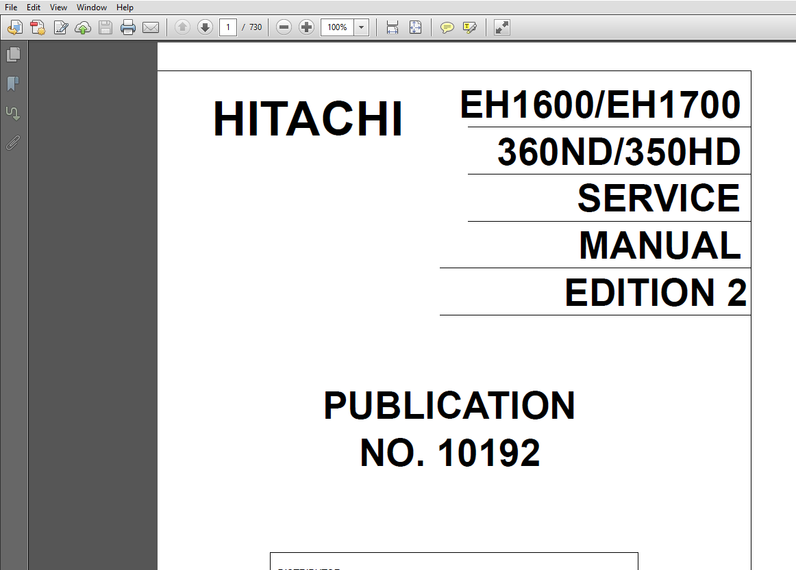
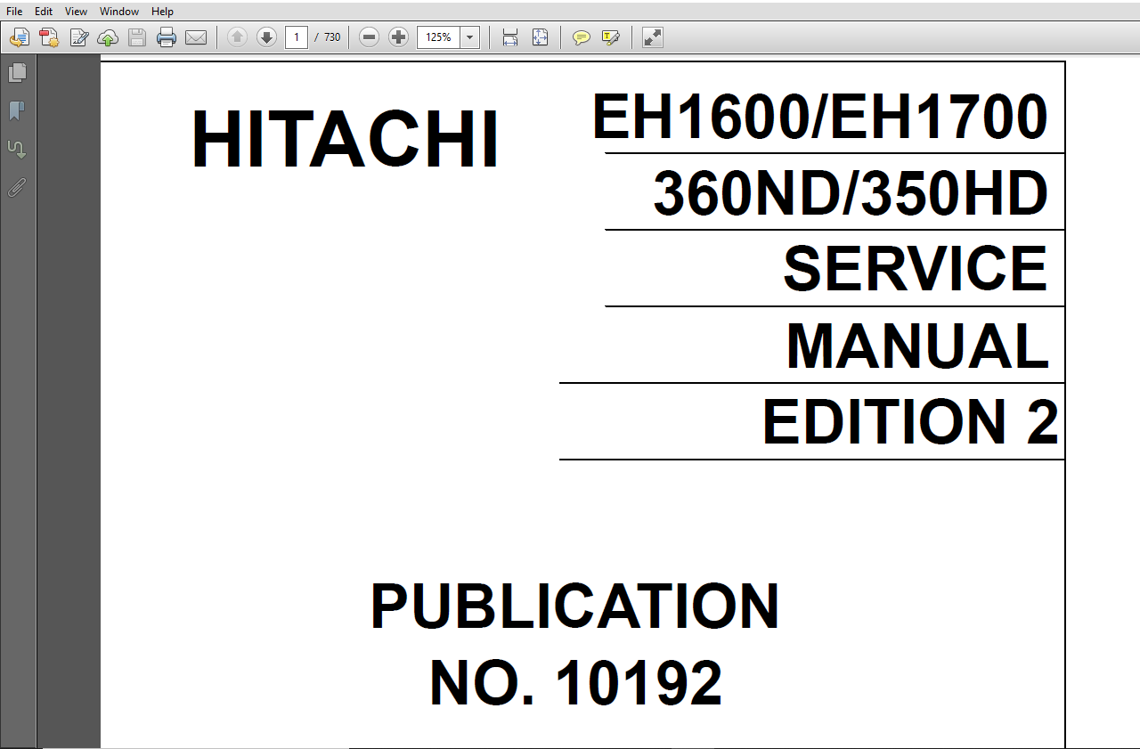
Hitachi EH1600 EH1700 360ND 350HD Dump Truck Service + Operator’s + Parts+ Electrical & Hydraulic Schematic Manual
FILE DETAILS:
Hitachi EH1600 EH1700 360ND 350HD Dump Truck Service + Operator’s + Parts+ Electrical & Hydraulic Schematic Manual
This Manual Includes:
- Hitachi EH1600 EH1700 360ND 350HD Dump Truck Service Manual (10192)
- Hitachi EH1600 EH1700 360ND 350HD Dump Truck Service Manual-2 (10192)
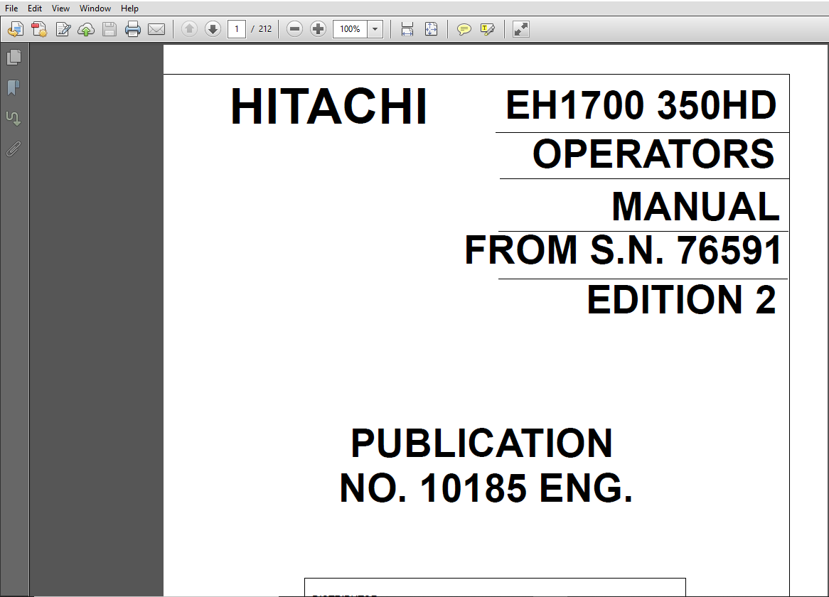
- Hitachi EH1700 350 HD Dump Truck Operators Manual (10185)
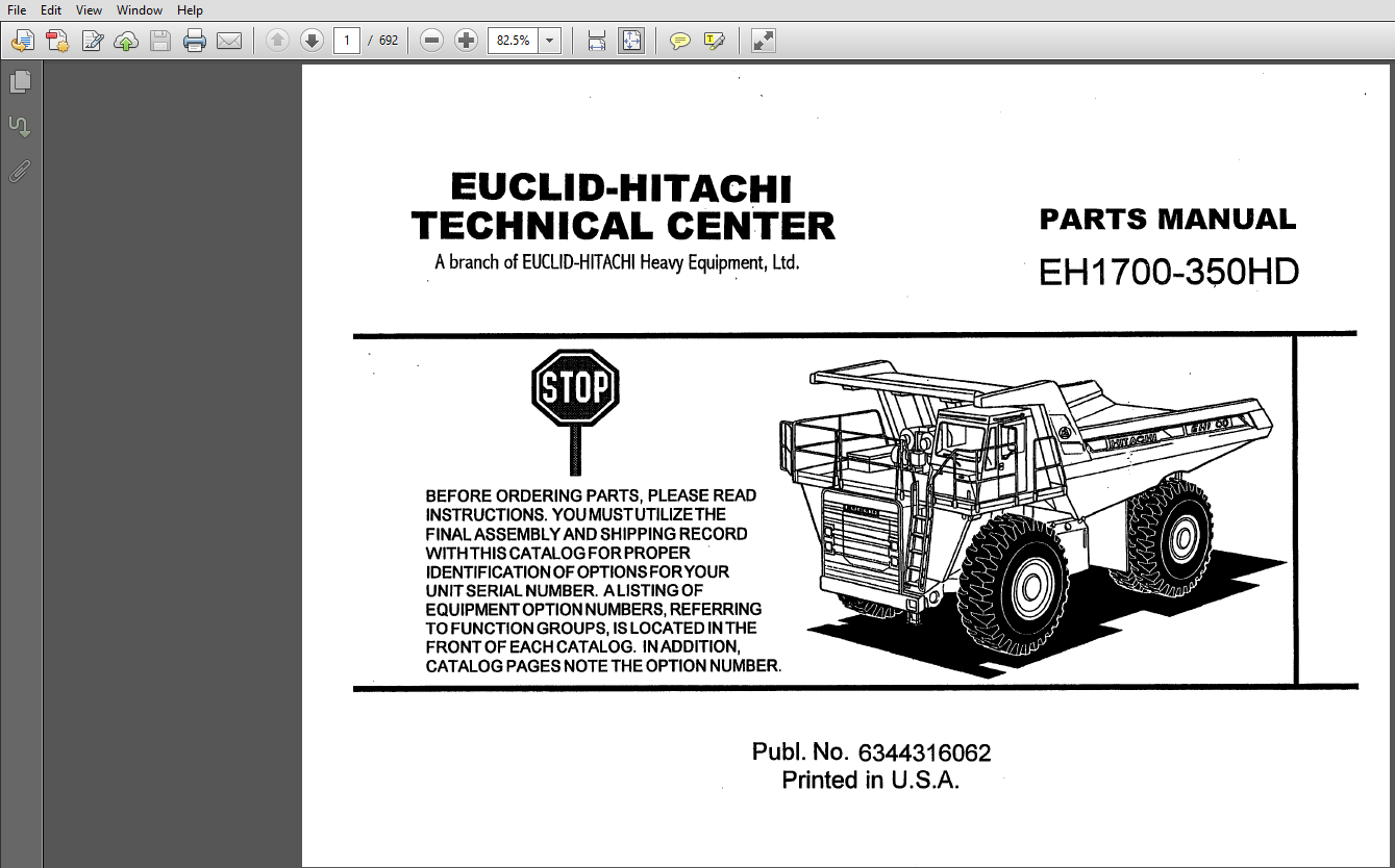
- Hitachi EH1700 350 HD Dump Truck Parts Manual (6344316062)
- Hitachi EH1700 Dump Truck Electrical Schematic Manual
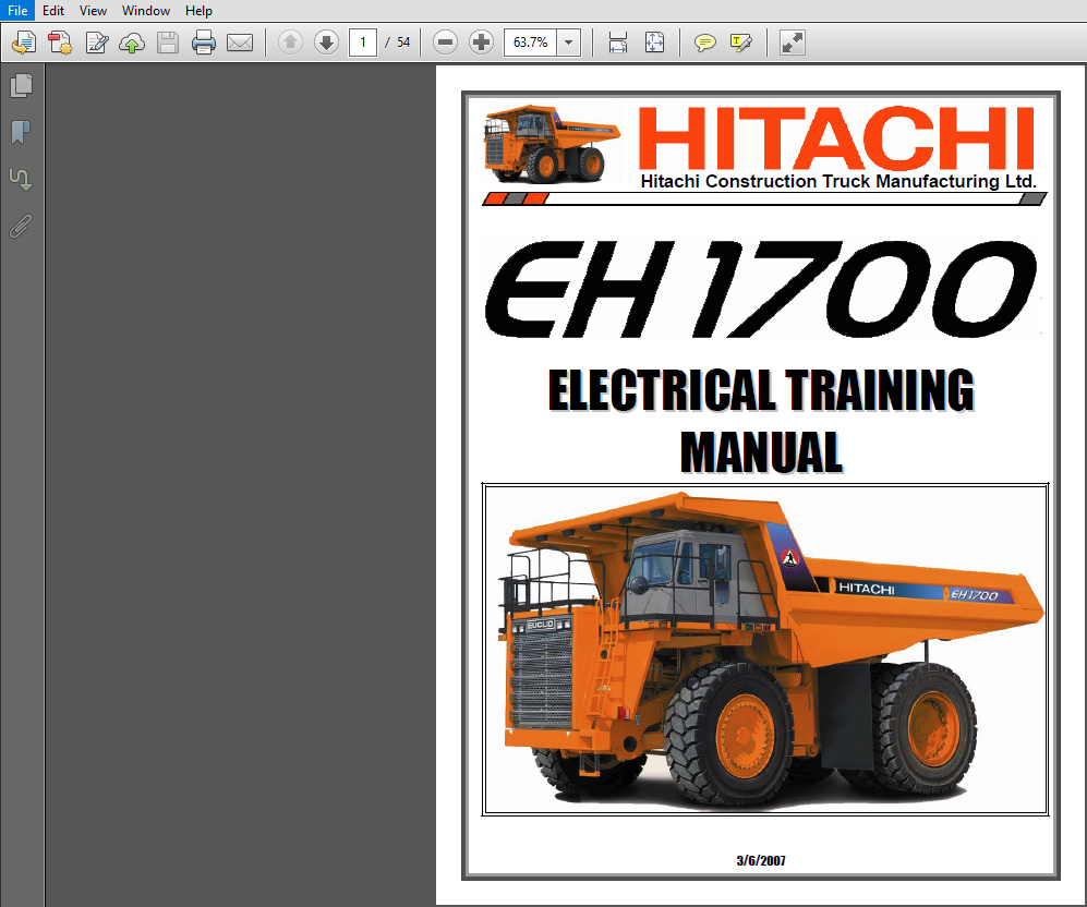
- Hitachi EH1700 Dump Truck Electrical Training Manual
- Hitachi EH1700 Dump Truck Hydraulic Schematic Manual
- Hitachi EH1700 Dump Truck Hydraulic Training Manual
SCREENSHOTS OF THE MANUAL:
DESCRIPTION:
Hitachi EH1600 EH1700 360ND 350HD Dump Truck Service + Operator’s + Parts+ Electrical & Hydraulic Schematic Manual
- This Operators Manual is intended as a guide for the correct use and maintenance of the machine. The manual should always be kept in the vehicle. Carefully read the manual before starting and operating the machine or before carrying out any preventive maintenance.
- We have taken many hours in designing and producing the safest and most efficient equipment possible. All this may be wasted if you do not read the safety instructions or if you do not follow them.
- Make yourself familiar with all controls and instructions and keep this manual in the machine for handy reference. If the manual is lost, it should be replaced immediately. Machines rarely cause accidents, whereas people do. A safety conscious person and a well maintained machine make a safe, efficient and profitable combination.
- This manual has been adapted to cover all markets, thus it may contain information about equipment not necessarily fitted to the version of the machine you have purchased.
- We therefore ask you to disregard information which is not applicable to your machine. We are continually striving to improve our products and therefore, reserve the right to make changes and improvements to the design whenever we consider that these increase the efficiency of the product.
- However, this does not commit us to introduce these improvements on products which have already been delivered or are in service. We also retain the right to change data and equipment, as well as instructions for service and maintenance without prior notice.
TABLE OF CONTENTS:
Hitachi EH1600 EH1700 360ND 350HD Dump Truck Service Manual (10192)
Title Page…………………………………………………………………………………………… 1
“Please Tell Us” Form for making Comments on the Service Manual……………………………………………. 2
Group 0 General Service Information…………………………………………………………………….. 3
SM638R1 Service Position and Safety Instructions……………………………………………………… 4
Group 1 Service and Operator’s Index……………………………………………………………………. 10
SM754R2 Automatic Centralized Lubrication System……………………………………………………… 11
SM789 Centralized Lubrication System (Non-Automatic)………………………………………………….. 21
SM878R1 Machine Specifications……………………………………………………………………… 23
SM401R5 Special Tools……………………………………………………………………………… 69
Group 2 Engine and Associated Systems Index……………………………………………………………… 0
SM651R2 Engine……………………………………………………………………………………. 85
SM645 Air Cleaners and Tubing………………………………………………………………………. 89
SM641 Fuel Lines and Fittings………………………………………………………………………. 99
SM794 Fast Fueling…………………………………………………………………………………101
SM408R1 Exhaust System……………………………………………………………………………..103
SM642R1 Cooling Lines and Fittings………………………………………………………………….. 0
SM646 Radiator…………………………………………………………………………………….111
SM805R1 Cold Start System (Option)…………………………………………………………………..117
SM451R1 Drive Coupling……………………………………………………………………………..121
Group 3 Electrical System and Instrument Index……………………………………………………………123
SM810R1 Electrical System – General………………………………………………………………….124
SM761R2 Contnronic Troubleshooting Guide……………………………………………………………..185
SM765 Battery Charging Procedure…………………………………………………………………….229
SM863 Starter and Mounting………………………………………………………………………….233
SM411 Pre Lube Starter and Mounting………………………………………………………………….245
SM755R3 Haultronic II – Load Weighing System………………………………………………………….249
Group 4 Power Transmission System Index………………………………………………………………….275
SM412R1 Transmission 360ND………………………………………………………………………….276
SM648R1 Transmission 350HD………………………………………………………………………….280
SM647 Transmission OIl Lines and Fittings…………………………………………………………….284
SM807R1 Transmission Shift Control…………………………………………………………………..286
SM876 Transmission – Electronic Retarder (Option)……………………………………………………..290
SM414R1 Transmission Oil Filter……………………………………………………………………..294
SM460 Transmission Mounting…………………………………………………………………………298
SM566R2 Front Driveshaft……………………………………………………………………………302
SM649 Rear Driveshaft………………………………………………………………………………308
SM816R1 Rear Axle………………………………………………………………………………….314
SM817R1 Differential……………………………………………………………………………….326
SM818R2 Rear Axle Planetary…………………………………………………………………………352
SM418R1 Power Take-Off……………………………………………………………………………..360
Group5.pdf…………………………………………………………………………………………… 0
Group 5 Brake System Index………………………………………………………………………….366
SM881R1 Hydraulic Brake System…………………………………………………………………..367
Schematics…………………………………………………………………………………374
Components…………………………………………………………………………………374
System Charging Suppy Pressure 0-9653kPa (0 – 1400 psi)…………………………………………375
System Charging Suppy Pressure 9653 to 18960kPa (1400 to 2750 psi)……………………………….376
System Charged Supply Pressure 16547 to 18960 kPa (2400 to 2750 psi)……………………………..377
Service Brake Apply…………………………………………………………………………378
Retarder Apply……………………………………………………………………………..379
Load/Dump Apply…………………………………………………………………………….380
Service Brake Apply with Rear Circuit Blow-Out…………………………………………………381
Front Brake Cut-Off Dash Switch “ON” Service Brake Apply Avove 12755 kPa (1850 psi) to Front Brakes….382
Front Brake Cut-Off Dash Switch “ON” Service Brake Apply Below 12755 kPa (1850 psi) to Front Brakes….383
Ignition Key “OFF”………………………………………………………………………….384
SM454R1 Front Brakes……………………………………………………………………………385
SM250R3 Rear Brakes – Wet Disc…………………………………………………………………..391
SM444R1 Brake Cooling System…………………………………………………………………….403
SM423R3 Active Traction Control Electronic Downhill Speed Control……………………………………407
SM678R3 Brake Valve…………………………………………………………………………….417
SM679R1 Retarder Control Valve…………………………………………………………………..432
SM887 Retarder Contol Valve – ATC………………………………………………………………..436
SM510R2 Brake Accumulator……………………………………………………………………….440
SM819 Parking Brake Actuator and Linkage………………………………………………………….446
SM820 Parking Brake…………………………………………………………………………….450
Group6.pdf…………………………………………………………………………………………… 0
Group 6, Wheel Suspension & Steering System Index……………………………………………………..458
SM783R2, Front Axle…………………………………………………………………………….459
SM784R1, Steering System………………………………………………………………………..471
Schematics, Conponents………………………………………………………………………477
System Charging 0 to 18960 kPa (0 to 2750 psi)…………………………………………………478
System Charged 18960 kPa (2750 psi)…………………………………………………………..479
System Standby 3447 kPa (500 psi) System Pressure 16547 to 18960 kPa (2400 to 2750 psi)…………….480
Right Turn (Park Brake Released)……………………………………………………………..481
Left Turn………………………………………………………………………………….482
Wheel Shock………………………………………………………………………………..483
Bleed Down (Key Off)………………………………………………………………………..484
SM423R2, Steering Column and Mounting…………………………………………………………….485
SM785R1, Steering Cylinder………………………………………………………………………489
SM650R1, Steering Pump………………………………………………………………………….499
SM556R2, Relief Check-Bleed Valve………………………………………………………………..521
SM435R1 Steering Control Valve…………………………………………………………………..527
SM426R2, Accumulator……………………………………………………………………………541
Group7thruGroup9.pdf………………………………………………………………………………….. 0
Group 7, Frame, Suspension and Wheel System Index……………………………………………………..549
SM825, Frame-General……………………………………………………………………………550
SM643R2, Front Suspension……………………………………………………………………….564
SM644R2, Rear Suspension………………………………………………………………………..576
SM812R1, Lifting/Jacking Procedures………………………………………………………………588
SM822, Front Wheel……………………………………………………………………………..596
SM823R1, Rear Wheels……………………………………………………………………………602
SM436R3, Tires/Rims/Inflation……………………………………………………………………609
Group 8, Cab Index…………………………………………………………………………………620
SM480R1, Cab Mounting…………………………………………………………………………..621
SM640 Air Conditioning System……………………………………………………………………623
Group 9, Hydraulic System and Other Functions Index……………………………………………………645
SM655R1, Hydraulic Hoist System………………………………………………………………….646
Schematics, Components………………………………………………………………………652
Raise……………………………………………………………………………………..653
Hold………………………………………………………………………………………654
Float……………………………………………………………………………………..655
Powerdown………………………………………………………………………………….656
Manual Floatdown……………………………………………………………………………657
SM654 Hydraulic Oil Tank………………………………………………………………………..658
SM769R1, Hydraulic Control Valve…………………………………………………………………660
SM652, Motion Control Valve……………………………………………………………………..688
SM343R1, Hydraulic Pump and Mounting……………………………………………………………..694
SM478R2, Body Cylinder………………………………………………………………………….711
SM439R2, Body and Mounting………………………………………………………………………719
Hitachi EH1600 EH1700 360ND 350HD Dump Truck Service Manual-2 (10192)
EH1600 EH1700 Group0 to Group4.pdf……………………………………………………………………… 1
Title Page……………………………………………………………………………………….. 1
“Please Tell Us” Form for making Comments on the Service Manual………………………………………… 2
Group 0 General Service Information…………………………………………………………………. 3
SM638R1 Service Position and Safety Instructions………………………………………………….. 4
Group 1 Service and Operator’s Index………………………………………………………………… 10
SM754R2 Automatic Centralized Lubrication System………………………………………………….. 11
SM789 Centralized Lubrication System (Non-Automatic)………………………………………………. 21
SM878R1 Machine Specifications………………………………………………………………….. 23
SM401R5 Special Tools………………………………………………………………………….. 69
Group 2 Engine and Associated Systems Index………………………………………………………….. 0
SM651R2 Engine………………………………………………………………………………… 85
SM645 Air Cleaners and Tubing…………………………………………………………………… 89
SM641 Fuel Lines and Fittings…………………………………………………………………… 99
SM794 Fast Fueling……………………………………………………………………………..101
SM408R1 Exhaust System………………………………………………………………………….103
SM642R1 Cooling Lines and Fittings………………………………………………………………. 0
SM646 Radiator…………………………………………………………………………………111
SM805R1 Cold Start System (Option)……………………………………………………………….117
SM451R1 Drive Coupling………………………………………………………………………….121
Group 3 Electrical System and Instrument Index………………………………………………………..123
SM810R1 Electrical System – General………………………………………………………………124
SM761R2 Contnronic Troubleshooting Guide………………………………………………………….185
SM765 Battery Charging Procedure…………………………………………………………………229
SM863 Starter and Mounting………………………………………………………………………233
SM411 Pre Lube Starter and Mounting………………………………………………………………245
SM755R3 Haultronic II – Load Weighing System………………………………………………………249
Group 4 Power Transmission System Index………………………………………………………………275
SM412R1 Transmission 360ND………………………………………………………………………276
SM648R1 Transmission 350HD………………………………………………………………………280
SM647 Transmission OIl Lines and Fittings…………………………………………………………284
SM807R1 Transmission Shift Control……………………………………………………………….286
SM876 Transmission – Electronic Retarder (Option)………………………………………………….290
SM414R1 Transmission Oil Filter………………………………………………………………….294
SM460 Transmission Mounting……………………………………………………………………..298
SM566R2 Front Driveshaft………………………………………………………………………..302
SM649 Rear Driveshaft…………………………………………………………………………..308
SM816R1 Rear Axle………………………………………………………………………………314
SM817R1 Differential……………………………………………………………………………326
SM818R2 Rear Axle Planetary……………………………………………………………………..352
SM418R1 Power Take-Off………………………………………………………………………….360
EH1600 EH1700 Group5.pdf……………………………………………………………………………….366
Group 5 Brake System Index………………………………………………………………………….366
SM881R1 Hydraulic Brake System…………………………………………………………………..367
Schematics…………………………………………………………………………………374
Components…………………………………………………………………………………374
System Charging Suppy Pressure 0-9653kPa (0 – 1400 psi)…………………………………………375
System Charging Suppy Pressure 9653 to 18960kPa (1400 to 2750 psi)……………………………….376
System Charged Supply Pressure 16547 to 18960 kPa (2400 to 2750 psi)……………………………..377
Service Brake Apply…………………………………………………………………………378
Retarder Apply……………………………………………………………………………..379
Load/Dump Apply…………………………………………………………………………….380
Service Brake Apply with Rear Circuit Blow-Out…………………………………………………381
Front Brake Cut-Off Dash Switch “ON” Service Brake Apply Avove 12755 kPa (1850 psi) to Front Brakes….382
Front Brake Cut-Off Dash Switch “ON” Service Brake Apply Below 12755 kPa (1850 psi) to Front Brakes….383
Ignition Key “OFF”………………………………………………………………………….384
SM454R1 Front Brakes……………………………………………………………………………385
SM250R3 Rear Brakes – Wet Disc…………………………………………………………………..391
SM444R1 Brake Cooling System…………………………………………………………………….403
SM423R3 Active Traction Control Electronic Downhill Speed Control……………………………………407
SM678R3 Brake Valve…………………………………………………………………………….417
SM679R1 Retarder Control Valve…………………………………………………………………..432
SM887 Retarder Contol Valve – ATC………………………………………………………………..436
SM510R2 Brake Accumulator……………………………………………………………………….440
SM819 Parking Brake Actuator and Linkage………………………………………………………….446
SM820 Parking Brake…………………………………………………………………………….450
EH1600 EH1700 Group6.pdf……………………………………………………………………………….458
Group 6, Wheel Suspension & Steering System Index……………………………………………………..458
SM783R2, Front Axle…………………………………………………………………………….459
SM784R1, Steering System………………………………………………………………………..471
Schematics, Conponents………………………………………………………………………477
System Charging 0 to 18960 kPa (0 to 2750 psi)…………………………………………………478
System Charged 18960 kPa (2750 psi)…………………………………………………………..479
System Standby 3447 kPa (500 psi) System Pressure 16547 to 18960 kPa (2400 to 2750 psi)…………….480
Right Turn (Park Brake Released)……………………………………………………………..481
Left Turn………………………………………………………………………………….482
Wheel Shock………………………………………………………………………………..483
Bleed Down (Key Off)………………………………………………………………………..484
SM423R2, Steering Column and Mounting…………………………………………………………….485
SM785R1, Steering Cylinder………………………………………………………………………489
SM650R1, Steering Pump………………………………………………………………………….499
SM556R2, Relief Check-Bleed Valve………………………………………………………………..521
SM435R1 Steering Control Valve…………………………………………………………………..527
SM426R2, Accumulator……………………………………………………………………………541
EH1600 EH1700 Group7 to Group9.pdf………………………………………………………………………549
Group 7, Frame, Suspension and Wheel System Index……………………………………………………..549
SM825, Frame-General……………………………………………………………………………550
SM643R2, Front Suspension……………………………………………………………………….564
SM644R2, Rear Suspension………………………………………………………………………..576
SM812R1, Lifting/Jacking Procedures………………………………………………………………588
SM822, Front Wheel……………………………………………………………………………..596
SM823R1, Rear Wheels……………………………………………………………………………602
SM436R3, Tires/Rims/Inflation……………………………………………………………………609
Group 8, Cab Index…………………………………………………………………………………620
SM480R1, Cab Mounting…………………………………………………………………………..621
SM640 Air Conditioning System……………………………………………………………………623
Group 9, Hydraulic System and Other Functions Index……………………………………………………645
SM655R1, Hydraulic Hoist System………………………………………………………………….646
Schematics, Components………………………………………………………………………652
Raise……………………………………………………………………………………..653
Hold………………………………………………………………………………………654
Float……………………………………………………………………………………..655
Powerdown………………………………………………………………………………….656
Manual Floatdown……………………………………………………………………………657
SM654 Hydraulic Oil Tank………………………………………………………………………..658
SM769R1, Hydraulic Control Valve…………………………………………………………………660
SM652, Motion Control Valve……………………………………………………………………..688
SM343R1, Hydraulic Pump and Mounting……………………………………………………………..694
SM478R2, Body Cylinder………………………………………………………………………….711
SM439R2, Body and Mounting………………………………………………………………………719
Hitachi EH1700 350 HD Dump Truck Operators Manual (10185)
Title Page……………………………………………………… 1
Foreword……………………………………………………….. 2
Safety Regulations…………………………………………… 2
Safety Alert Symbol………………………………………….. 2
Unauthorized Modification of Rollover Protective Structure (ROPS)…. 3
Operation and Maintenance of the Machine……………………….. 3
Table of Contenfss………………………………………………. 4
Presentation……………………………………………………. 6
Engine……………………………………………………… 6
Power Transmission…………………………………………… 6
Brakes……………………………………………………… 6
Steering……………………………………………………. 6
Cab………………………………………………………… 6
Body……………………………………………………….. 6
Nameplates, Warning and Information Decals……………………… 7
Product Identification Number…………………………………. 11
Maintenance and Inspections…………………………………… 11
Instrument Panel………………………………………………… 14
Operators Controls………………………………………………. 44
Operating Instructions…………………………………………… 70
General Operating Rules………………………………………. 70
Operator’s Qualifications…………………………………….. 70
Duties of the Operator……………………………………….. 70
A Few Simple Safety Rules Before Operating……………………… 70
Operating with the Machine Near Overhead Wires or Cables…………. 72
Operating with the Machine Near High Voltage Overhead Power Lines…. 72
Signalling Diagram…………………………………………… 73
Procedure Before Starting…………………………………….. 74
Daily Walk Around Inspection………………………………. 74
Run-In Instructions………………………………………….. 75
Starting Engine……………………………………………… 76
Before Operating…………………………………………….. 80
Operating the Machine………………………………………… 81
Parking Machine………………………………………………105
Storage of Hitachi Rigid Haulers……………………………….106
Transporting…………………………………………………113
Roading……………………………………………………..122
Machine Stuck in Deep Sand, Snow or Mud…………………………123
Towing………………………………………………………124
Basic Preventive Maintenance………………………………………128
Service Position……………………………………………..128
A Few Simple Rules When Servicing………………………………129
Fire Prevention Measures………………………………………131
Waste Hazardous to the Environment……………………………..132
Basic Preventive Maintenance Interval Chart……………………..133
General Information…………………………………………..136
Centralized Service Manual (Option)…………………………….137
Engine………………………………………………………138
Air Cleaner System……………………………………………141
Fuel System………………………………………………….145
Cooling System……………………………………………….148
Electrical System…………………………………………….153
Power Transmission……………………………………………159
Brake System…………………………………………………165
Wheel Suspension and Steering………………………………….168
Frame, Springs and Wheels……………………………………..171
Cab…………………………………………………………173
Hydraulic System and Other Functions……………………………176
Chassis and Driveshaft Grease Fitting Locations………………….181
Lube Interval 50 Hours…………………………………….181
Lube Interval 50 Hours (continued) / 1000 Hours………………182
Specifications…………………………………………………..184
Recommended Lubricants………………………………………..184
Service Specifications………………………………………..186
Engine…………………………………………………..186
Electrical……………………………………………….187
Power Transmission………………………………………..190
Brake System……………………………………………..191
Steering System…………………………………………..192
Wheels…………………………………………………..193
Cab……………………………………………………..193
Hydraulic System………………………………………….194
Machine Weights………………………………………………195
Performance Chart…………………………………………….195
Retarder Charts………………………………………………196
Machine Dimensions……………………………………………197
Bolt Torque Chart, General…………………………………….198
Alphabetical Index……………………………………………….208
Hitachi EH1700 Dump Truck Electrical Schematic Manual
E12625122P06_01.tif…. 1
E12625122P06_02.tif…. 2
E12625122P06_03.tif…. 3
E12625122P06_04.tif…. 4
E12625122P06_05.tif…. 5
E12625122P06_06.tif…. 6
E12625122P06_07.tif…. 7
E12625122P06_08.tif…. 8
E12625122P06_09.tif…. 9
E12625122P06_10.tif….10
E12625122P06_11.tif….11
E12625122P06_12.tif….12
E12625122P06_13.tif….13
E12625122P06_14.tif….14
Hitachi EH1700 Dump Truck Electrical Training Manual
Batteries and Alternator……………………………………….. 7
Batteries…………………………………………………. 7
Figure 1: Battery Bank Connection with Power Bus…………………. 7
Battery Equalizer………………………………………….. 7
Figure 2: Battery Equalizer Connection………………………….. 8
Alternator………………………………………………… 8
Starting Circuit………………………………………………. 9
Starting Circuit (With Pre-lube Option)………………………….. 9
Engine Control – Detroit Diesel DDEC IV Series 2000………………..10
Accelerator Pedal…………………………………………..10
Engine Shutdown Switch………………………………………10
Air Filter Switch #1 and #2………………………………….10
Engine Coolant Level Switch…………………………………10
Engine Control – Cummins Quantum QST-30…………………………..10
Accelerator Pedal…………………………………………..10
Air Filter Switch #1 and #2………………………………….10
Engine Coolant Level Switch…………………………………11
Engine Control – Centry Electronic Engine Option…………………..11
Monitoring Circuits…………………………………………….12
Figure 3: Instrument Panel Display………………………………12
Engine Oil Pressure…………………………………………12
Brake Temperature…………………………………………..12
Brake/Steer Pressure………………………………………..13
Tachometer…………………………………………………13
Gauges and Warning Lights……………………………………….14
Central Warning (Red Warning Light)…………………………..14
Figure 4: Central Warning Light…………………………………14
Figure 5: Gauges………………………………………………15
Brake/Steering Oil Pressure Gauge…………………………….15
Brake Temperature Gauge……………………………………..15
Engine Coolant Temperature…………………………………..15
Transmission Temperature Gauge……………………………….16
Speedometer………………………………………………..16
Tachometer…………………………………………………16
Figure 6: Warning Lights (ALL)………………………………….17
Figure 7: Warning Lights……………………………………….17
Engine Oil Pressure (Red Warning Light)……………………….17
Transmission Pressure (Red Warning Light)……………………..17
Engine Coolant Temperature…………………………………..18
Brake Pressure (Red Warning Light)……………………………18
Park Brake Pressure (Red Warning Light)……………………….18
Steer Pressure (Red Warning Light)……………………………18
Transmission (Converter) Oil Temperature (Yellow Warning Light)….18
Figure 8: Warning Lights……………………………………….18
Figure 9: Warning Lights……………………………………….19
Engine Service (Yellow Warning Light)…………………………19
Engine Shutdown (Red Warning Light) ………………………….19
Steer Oil Temperature (Red Warning Light)……………………..19
Brake Temperature (Yellow Warning Light)………………………19
Figure 10: Warning Lights………………………………………20
Alternator (Red Warning Light)……………………………….20
Engine Coolant Level (Red Warning Light)………………………20
Filters (Yellow Warning Light)……………………………….20
Transmission Malfunction(Yellow Warning Light)…………………20
Figure 11: CEC Trouble Code Example……………………………..21
Indicator Lights……………………………………………….21
Turn Signal/Hazard (Green Light)……………………………..21
High Beam (Blue Light)………………………………………21
Lighting Circuits………………………………………………22
Low Beams………………………………………………….22
High Beams…………………………………………………22
Marker Lights………………………………………………22
Tail Lights………………………………………………..22
Reverse Lights……………………………………………..22
Turn/Hazard Signal Lights……………………………………23
Dome Light…………………………………………………23
Service Lights……………………………………………..23
Brake and Retard Circuits……………………………………….24
Brake Circuit………………………………………………24
Automatic Traction Control (ATC)……………………………..24
Retarder Circuit……………………………………………24
Park Brake Circuit………………………………………….24
Load/Dump Brake Circuit……………………………………..25
Hill Hold Circuit (Optional)…………………………………25
Electronic Downhill Speed Control (EDSC) Circuit……………….25
Automatic Traction Control (ATC) (Optional)…………………..26
Figure 12: ATC System………………………………………….26
Hoist Circuit………………………………………………….28
Figure 13: Contronics Service Tool Display – Hoist Solenoids……….28
Hoist Lever………………………………………………..28
Figure 14: Hoist Lever…………………………………………28
Proximity Switch……………………………………………28
Hoist Raise and Lower PWM Solenoid……………………………29
Figure 15: Hoist Raise and Lower Solenoids……………………….29
Hoist Controller……………………………………………29
Figure 16: Hoist Controller…………………………………….30
Figure 17: Hoist Controller Circuit Board………………………..30
Table 1: U1 Positions………………………………………….31
Table 2: Fault Codes…………………………………………..32
Contronics – General Information…………………………………33
Contronic ECU……………………………………………..34
Contronic Service Tool and Display…………………………..35
Contronic LCD Panel…………………………………………35
Figure 18: Contronic LCD Panel………………………………….35
Circuit Board………………………………………………….37
Hitachi EH1700 Dump Truck Hydraulic Schematic ManualE12622594P01 Steering.tif………..1
E12623716P01 Brakes No ATC.tif……2
E12623716P01 Brakes With ATC.tif….3
E12622595P01 Hoist_EDIT.TIF………4
More products