$35
Hitachi EH1700 Dump Truck Hydraulic Schematic Manual PDF DOWNLOAD
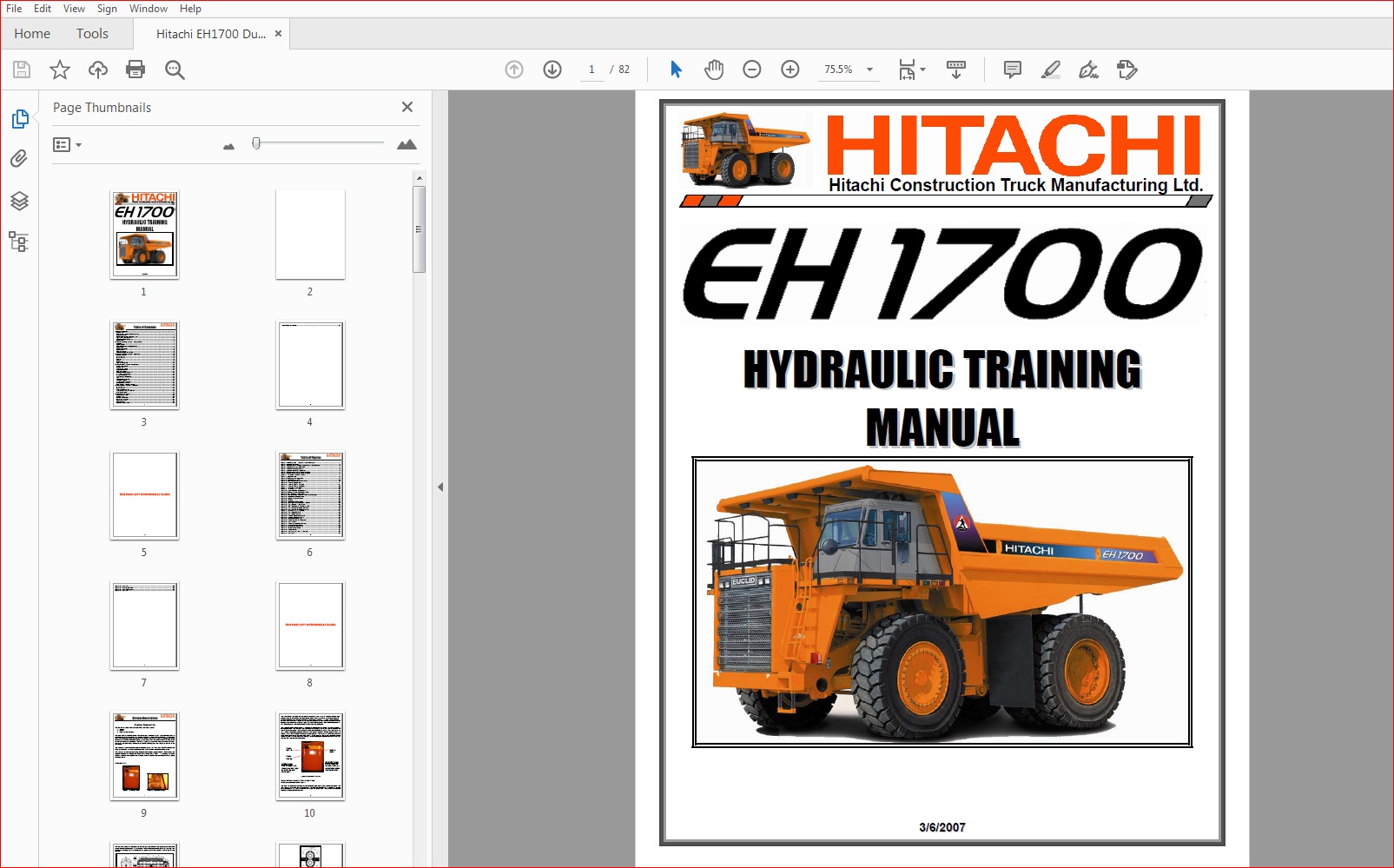
Hitachi EH1700 Dump Truck Hydraulic Schematic+Training Manual
FILE DETAILS:
Hitachi EH1700 Dump Truck Hydraulic Schematic+Training Manual
Language : English
Pages :86
Downloadable : YES
Format : PDF
DESCRIPTION:
Hitachi EH1700 Dump Truck Hydraulic Schematic+Training Manual
System Description:
The EH1700 Hydraulic System can be divided into three systems:
1. Steering
2. Brakes
3. Hoist and Brake Cooling
The three systems share the same outboard mounted hydraulic oil tank. The hydraulic oil tank is internally divided in two sections, the steering and brake section and hoist section. A piston type pump with unloading feature supplies oil to the steering and brake systems, a tandem gear pump provides oil to the hoist and brake cooling system. Both pumps are driven off the PTO Drive driven off the rear of the main alternator. The PTO is coupled by a driveline to the rear of the alternator. The hoist brake and cooling tandem pump and the steering pump are coupled to the rear of the PTO Drive.
The hydraulic system has three separate hydraulic filters. One filter is for both the steering and brake cooling circuit and the two remaining filters are for the hoist and brake cooling circuit. The steering and brake systems share the same hydraulic tank, pump and filter. Both systems are supplied hydraulic oil through the Relief Check Bleed (RCB) valve. The steering and brake systems have their own separate accumulators which will provide hydraulic fluid in case of a pump or system failure.
TABLE OF CONTENTS:
Hitachi EH1700 Dump Truck Hydraulic Schematic+Training Manual
Figure 1: Hydraulic Tank Figure 2: Hydraulic Pumps 1
Figure 3: Hydraulic Oil Levels 2
Figure 4: Hoist and Brake Cooling Tandem Gear Pump Cutaway 3
Figure 5: Typical Gear Pump Operation 4
Figure 6: Steer Piston Pump Cutaway 5
Figure 7: Typical Piston Pump Operation 6
Figure 8: Control and Unloading Valve Locations 7
Figure 9: Control and Unloading Valve Operation 8
Figure 10: Steering – System Standby 11
Figure 11: Hydraulic Filter 13
Figure 12: Cutaway of Steering Filter 15
Figure 13: Filter Indicator Light 16
Figure 14: Relief-Check-Bleed (RCB) Valve 16
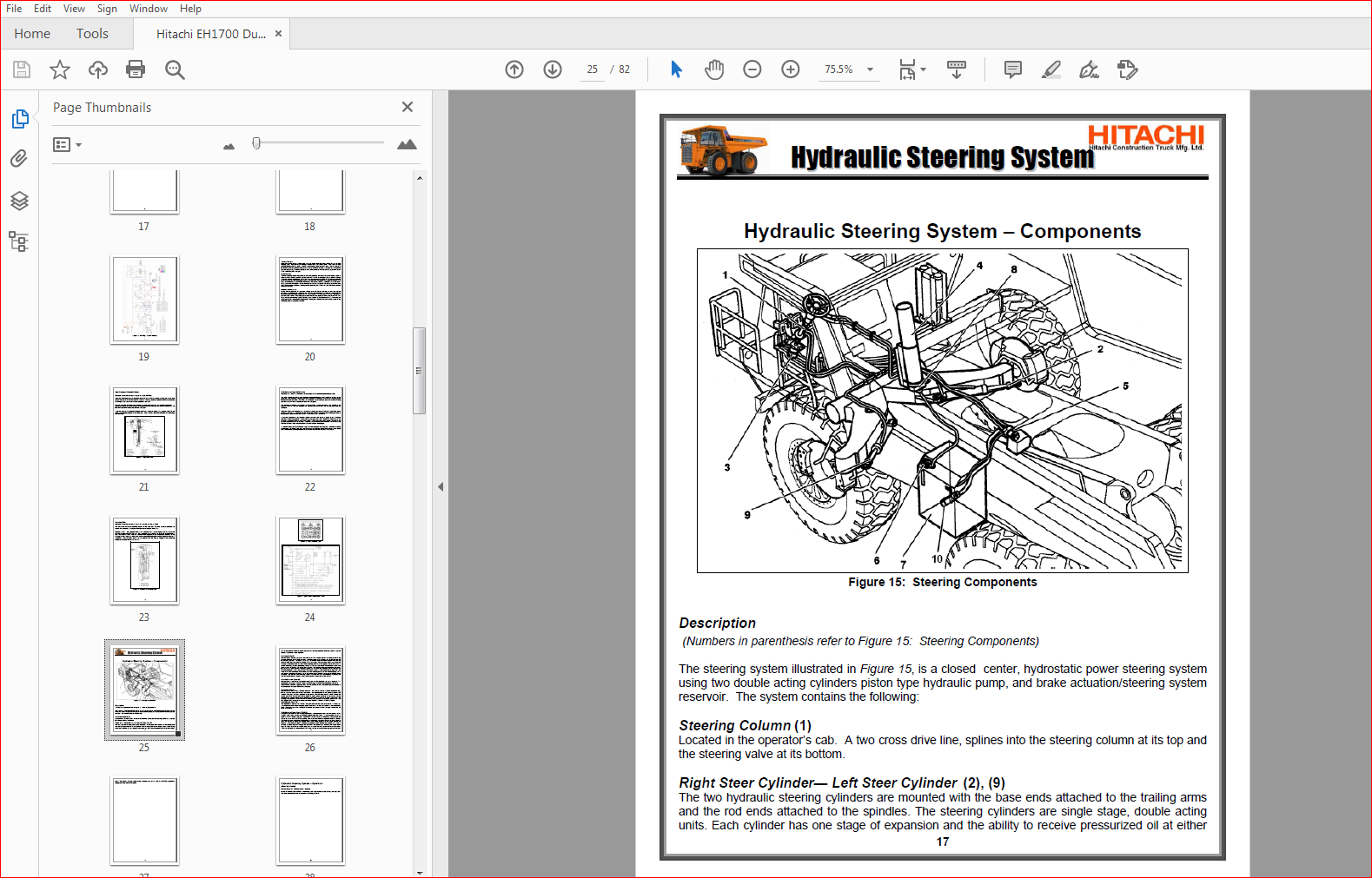
Figure 15: Steering Components 17
Figure 16: Steering System: Standby 21
Figure 17: Steering System: Charging 23
Figure 18: Steering – Right Turn 25
Figure 19: Steering – Left Turn 27
Figure 20: Hydraulic Brake Components 32
Figure 21: Retarder Control Valve/Brake Valve 33
Figure 22: Low Pressure Sensor Valve 34
Figure 23: Steer and Brake Pressure Central Warning Lights 34
Figure 24: Load/Dump Solenoid Valve 35
Figure 25: Front Brake Cutoff Switch 35
Figure 26: Hill Hold 36
Figure 27: Load/Dump Brake Switch 38
Figure 28: Left/Right Brake Solenoids – Locator 39
Figure 29: Brake Coolant Temp Sensor 39
Figure 30: RTD Temperature Resistance Table 40
Figure 31: Brake System Charging – NO ATC 43
Figure 32: Brake System Charging WITH ATC 44
Figure 33: Brakes NO ATC – Charged 47
Figure 34: Brake Apply NO ATC 49
Figure 35: Brake Apply with ATC 50
Figure 36: Retarder Apply Without ATC 53
Figure 37: Retarder Apply WITH ATC 54
Figure 38: Load Dump Brake Apply 57
Figure 39: Front Brake Cut-off Installation 59
Figure 40: Hoist System 60
Figure 41: Control Lever / Body Positions 61
Figure 42: Hydraulic Control Valves 62
Figure 43: Manual Float Down Valve 63
Figure 44: Motion Control Valve 63
Figure 45: Cooling Filters 64
Figure 46: Hoist Raise and Lower Solenoids 65
Figure 47: Hoist Float 67
IMAGES PREVIEW OF THE MANUAL:
More products