$45
Honda 250.350 CB250 CL250 CB350 CL350 Shop Manual - PDF DOWNLOAD
Honda 250.350 CB250 CL250 CB350 CL350 Shop Manual - PDF DOWNLOAD
FILE DETAILS:
Honda 250.350 CB250 CL250 CB350 CL350 Shop Manual - PDF DOWNLOAD
Language :English
Pages :219
Downloadable : Yes
File Type : PDF
IMAGES PREVIEW OF THE MANUAL:
DESCRIPTION:
Honda 250.350 CB250 CL250 CB350 CL350 Shop Manual - PDF DOWNLOAD
FOREWORD
- This Manual is a guide to the inspection and servicing of the Honde motorcycle; Hont 250/350, Models CB250/350 and CL250/350. The CL350 is used as a base for this manual, therefore, the photographs and drawing: are of this model.
- However, since all models are practically identical, the information contained will apply equally well to the other models. Any information which are peculiar to any of the models will be identified to the applicable model by the use of the codes listed below.
Applicable To
All CB/CL250, 350 models
All CB250, CB350 models
All CL250, CL350 models
All CB250, CL250 models
All CB350, CL350 models
Code
Honda 250/350
CB250/350
CL250/350
CB/CL250
CB/CL350
- Service and maintenance procedures are outlined in detail to enable the shop personnel to locate the problems rapidly and make repairs with much saving in time.
- This manual has been prepared by major groups, assemblies and sections for ·easy use. Further, all work procedures are descriptive and accompanied by many photographs and drawings for clarity.
- Changes to any portion of this manual or supplement information will be notified by the Service Bulletin. Keep in mind that proper servicing produces satisfied customer and satisfied customer is good business. SERVICE
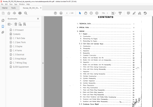
TABLE OF CONTENTS:
Honda 250.350 CB250 CL250 CB350 CL350 Shop Manual - PDF DOWNLOAD
1 TECHNICAL DATA
2 SPECIAL TOOL
3 ENGINE
3 1 Engine
A Construction
B Dismounting the Engine
C Remounting the Engine
3 2 Cam Case and Cylinder Head
A Construction
B Disassembly
C Inspection
D Reassembly
E Camshaft Costruction ·
F Rocker Arm and Rocker Arm Pin
G Rocker Arm and Rocker arm pin Disassembly
H Inspection ·
I Rocker Arm and Rocker Arm Pin Reassembly
J Valve and Valve Spring Construction
K Valve and Valve Spring Disassembly ,
L Inspection ·
M Val~e and Valve Spring Reassembly
N Cylinder Construction
0 Cylinder Disassembly
P Cylinder Inspection
Q Cylinder Reassembly
R Piston Description
S Piston Ring Construction
T Piston and Piston Ring Disassembly
U Piston and Piston Ring Inspection
V Piston and Piston Ring Reassembly
W Cam Chain Tensioner and Guide Roller Construction
X Tensioner and Guide Roller Disassembly
Y Tensioner and Guide Roller Reassembly ,·~
3 3 Crankcase Cover (Right)
Disassembly
Reassembly
D Oil Filter Construction
E Oil Filter Disassembly
F Oil Filter Reassembly
G Clutch Construction _
H Oil Pump Construction
I Clutch Disassembly
J Clutch Inspection
K Clutch Reassembly
3 4 Crankcase Cover (Left)
A Construction -
B Disassembly 42
C Reassembly 42
3 5 Upper and Lower Crankcase 43
A- Construction 43
B Oil Separator Operation 43
C Upper and Lower Crankcase Disassembly 43
D Upper and Lq_wer Crankcase Inspection 44
E Upper and Lower Crankcase Reassembly 44
f_ Crankshaft Construction
G; Connecting Rod Construction
H · Crankshaft Disassembly
I Crankshaft Inspection
J ° Crankshaft Reassembly , -
Kick Starter
Kick Starter
Kick Starter
Kick Starter
Transmission
Transmission
Tr,ansmission
Construction
Disassembly -
Inspection
Reassembly
Disassembly
Inspection ·
R Transmission Reassembly
S -Gear Shift Construction
T Gear Shift Disassembly
A Construction 61
B Disassembly 61
C Inspection ~ /_ · 62
D Reassembly §y " 63
4 2 Fork Top Bridge 63
A Construction· 63
t; Disassembly 64
C Inspection 64
D Reassembly 64
4 3 Front Cushion 65
A Construction · 65
B Disassembly 67
C Inspection 68
D Reassembly 68
4 4 Steering Stem ; 70
A Construction 70
B Disassembly · 70
~5 " ,; ~ ~ir; 1!( ~
A Construction - 71
B Disassembly 72
C Inspection 72
D Reassembly 72
4 6 Frame Body · · ·_ · 73
A Construction · 73
B · ·D_isassembly _ 7 4
C Inspection 7 4
D Reassembly 7 4
4 7 Seat , · 75
A Construction 7 5
B Disassembly · 75
C Inspection 75
D Reassembly 7 5
4 8 Stand, Brake Pedal and Step Bar · , · 76
A Construction - 76 i
·~ ;[,~ \ ;'~1
B Disassembly , , · 7'6" -~rt -,, ~i(l' ;, · , ,
Inspection 77
Reassembly 77
Muffler 78
Construction 78
Disassembly 78
Inspection 78
Reassembly 78
Air Cleaner 78
Construction 78
Disassembly 79
Inspection ; 79
Reassembly 79
Rear Fork and Rear Fender 80
Construction 80
Disassembly 81
Inspection 81
Reassembly 82
Rear Cushion 82
Construction
Disassembly
Inspection 84
Reassembly 84
Front Wheel 86
Construction 86
Disassembly 86
Inspection 88
Reassembly 88
Rear Wheel 90
Construction 90
Disassembly 91
Inspection 92
Reassembly 94
5 ELECTRICAL PARTS 97
5 1 Electrical Equipment 97
5 2 Power Supply System 97
5 3 Ignition Circuit
A Ignition System
C Spark Advancer 99
D Contact Breaker 100
E Condenser 101
F Spark Plug , 102
5 4 Power Circuit 108
A A C Generator 108
B Current Limiter 108
C Selenium Rectifier 111
D Battery 113
5 5 Electric Starter 119
A Starting Circuit 119
B Starting Motor Characteristics 120
C Starter Reduction 120
D Removal 12i
E Servicing 121
F Starting Clutch 122
G Starter Solenoid Switch 124 ,
5 6 Safety Devices 125 1
A Horn 125 ,
B Servicing
C Tail-Stoplight
D Pilot Lamp
E Speedometer /Tachometer 128 i I
F Characteristics of the Speedometer /Tachometer 129 I
G Headlight 130
H Flasher Relay 131
5 7 Switches 132
A Combination Switch 132
B Stoplight Switch ■ 133
C Starter /Lighting Switch 133
D Winker-Horn Switch - 133
E Neutral Switch 133
5 8 Wire Harness 134
5 9 Service Tester 135
A Operating Instructions 135 -i
B Meter Reading
Usage by Item
5 10 Trouble Shooting and Correct Action
6 INSPECTION AND ADJUSTMENT , 145
6 1 Preventive Maintenance 145
A Engine Tune-Up · 145
B Lubrication · 156
C Drive Chain Adjustment 158
D Brake Adjustment , 159
E Battery Inspection 160
F Checking Parts for Tightness 1 61
6 2 Periodical Inspection and Maintenance 163
6 3 Trouble Shooting 164
7 WIRING DIAGRAM 175
WIRING DIAGRAM (General Type) 17 5
WIRING DIAGRAM (U S A Type) 176
WIRING DIAGRAM (U K Type) 177
WIRING DIAGRAM (Germany Typel 178
S.M 16/3/2025

