$45
Isuzu ANTI-LOCK BRAKE SYSTEM(ABS) Workshop Manual (Section 5A4)- PDF DOWNLOAD
Isuzu ANTI-LOCK BRAKE SYSTEM(ABS) Workshop Manual (Section 5A4)- PDF DOWNLOAD
FILE DETAILS:
Isuzu ANTI-LOCK BRAKE SYSTEM(ABS) Workshop Manual (Section 5A4)- PDF DOWNLOAD
Language : English
Pages : 182
Downloadable : Yes
File Type : PDF
IMAGES PREVIEW OF THE MANUAL:
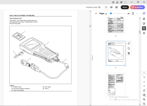
TABLE OF CONTENTS:
Isuzu ANTI-LOCK BRAKE SYSTEM(ABS) Workshop Manual (Section 5A4)- PDF DOWNLOAD
TOP 0
ANTI-LOCK BRAKE SYSTEM (ABS) 1
Sec5A4ANTI-LOCK BRAKE SYSTEM (ABS) 2
Service Precaution 2
General Description 6
System Components 7
Electronic Hydraulic Control Unit (EHCU) 7
Hydraulic Unit (HU) 7
ABS Warning Light 7
Wheel Speed Sensor 7
Normal and Anti-lock Braking 7
Brake Pedal Travel 8
Acronyms and Abbreviations 8
General Diagnosis 8
General Information 8
ABS Service Precautions 8
Computer System Service Precautions 8
General Service Precautions 9
Note on Intermittents 9
Test Driving ABS Complaint Vehicles 9
“ABS” Warning Light 9
Normal Operation 9
Basic Diagnostic Flow Chart10
Basic Inspection Procedure10
Tech 2 Scan Tool11
Tech 2 Features12
Getting Started12
Operating Procedure (For Example)13
DTC Modes14
DTC Information Mode14
Plotting Snapshot Graph15
Plotting Graph Flow Chart (Plotting graph after obtaining vehicle information)16
Flow Chart for Snapshot Replay (Plotting Graph)17
Tech 2 Data Display18
Special Function18
EHCU Connector Pin-out Checks22
Circuit Diagram-FOR 12VOLT23
Connector List27
Part Location30
Symptom Diagnosis31
Chart A-1 ABS Works Frequently But Vehicle Does Not Decelerate31
Chart TA-1 ABS Works Frequently But Vehicle Does Not Decelerate (Use TECH 2)31
Chart A-2 Uneven Braking Occurs While ABS Works32
Chart A-3, TA-3 The Wheels Are Locked32
Chart A-4 Brake Pedal Feed Is Abnormal33
Chart A-5, TA-5 Braking Sound (From Hydraulic Unit) Is Heard While Not Braking34
Diagnostic Trouble Codes35
Diagnosis BY “ABS” Warning Light Illumination Pattern36
Diagnostic Trouble Codes (DTCs)36
Chart B-1-1 With the key in the ON position (Before starting the engine) Warning light
(W/L) is not activated40
Chart 1 (DTC13/C0213) Vehicle Type Error41
Chart 2 (DTC14/C0214) Low Power Voltage of Rear Sensor or EHCU Abnormality41
Chart 3 (DTC15/C0215) EHCU Voltage OUT of Range42
Chart 4 (DTC25/C0225) Exhaust Brake Cut Circuit Abnormality43
Chart 5 (DTC33/C0233) Motor Drive Circuit Abnormality43
Chart 6 (DTC 34/C0234) Abnormal Motor Rotation43
Chart 7 (DTC41/C0241) Solenoid Valve Power Supply Abnormality44
Chart 8 (DTC 43, 45/C0243, C0245) Solenoid Valve Circuit Abnormality44
Chart 9 (DTC51/C0251) FL Speed Sensor Circuit Abnormality44
Chart 10 (DTC52/C0252) FR Speed Sensor Circuit Abnormality44
Chart 11 (DTC53/C0253) RL Speed Sensor Circuit Abnormality45
Chart 12 (DTC54/C0254) RR Speed Sensor Circuit Abnormality46
Chart 13 (DTC 61/C0261) Abnormal FL Speed Sensor Signal47
Chart 14 (DTC 62/C0262) Abnormal FR Speed Sensor Signal49
Chart 15 (DTC 63/C0263) Abnormal RL Speed Sensor Signal51
Chart 16 (DTC 64/C0264) Abnormal RR Speed Sensor Signal52
Chart 17 (DTC65/C0265) Tire Size Error53
Unit Inspection Procedure54
Chart C-1-1 FL Speed Sensor Output Inspection Procedure54
Chart C-1-2 FR Speed Sensor Output Inspection Procedure55
Chart C-1-3 RL Speed Sensor Output Inspection Procedure56
Chart C-1-4 RR Speed Sensor Output Inspection Procedure58
Chart TC-1 Sensor Output Inspection Procedure (Use TECH 2)59
Electronic Hydraulic Control Unit (EHCU)60
Removal60
Installation60
Front Speed Sensor61
Front Speed Sensor and Associated Parts61
Removal61
Inspection and Repair61
Installation61
Front Speed Sensor Rotor62
Front Speed Sensor Rotor and Associated Parts62
Removal62
Inspection and Repair63
Installation63
Rear Speed Sensor64
Rear Speed Sensor and Associated Parts64
Removal65
Inspection and Repair65
Installation65
Rear Speed Sensor Rotor66
Rear Speed Sensor Rotor and Associated Parts66
Removal66
Inspection and Repair66
Installation66
Special Tools68
DESCRIPTION:
Isuzu ANTI-LOCK BRAKE SYSTEM(ABS) Workshop Manual (Section 5A4)- PDF DOWNLOAD
Service Precaution:
- Always use the correct fastener in the proper location. When you replace a fastener, use ONLY the exact part number for that application. ISUZU will call out those fasteners that require a replacement after removal. ISUZU will also call out the fasteners that require thread lockers or thread sealant.
- UNLESS OTHERWISE SPECIFIED, do not use supplemental coatings (Paints, greases, or other corrosion inhibitors) on threaded fasteners or fastener joint interfaces. Generally, such coatings adversely affect the fastener torque and the joint clamping force, and may damage the fastener.
- When you install fasteners, use the correct tightening sequence and specifications. Following these instructions can help you avoid damage to parts and systems.
General Description:
- The Anti-lock Brake System (ABS) works on all four wheels.
- A combination of wheel speed sensor and Electronic Hydraulic Control Unit (EHCU) can determine when a wheel is about to stop turning and adjust brake pressure to maintain best braking.
- This system helps the drive maintain greater control of the vehicle under heavy braking conditions.
G.B 05/03/24
More products