$42
Isuzu Diesel Engine 4JJ1 Troubleshooting Manual ITE-3230 – PDF DOWNLOAD
Isuzu Diesel Engine 4JJ1 Troubleshooting Manual ITE-3230 – PDF DOWNLOAD
DESCRIPTION:
Isuzu Diesel Engine 4JJ1 Troubleshooting Manual ITE-3230 – PDF DOWNLOAD
Introduction
This Troubleshooting Manual describes the structure and the troubleshooting of
electronic control fuel injection system (common rail type) in 4JJ1 industrial engines.
Use this manual sufficiently to perform service work properly and quickly.
IMAGES PREVIEW OF THE MANUAL:
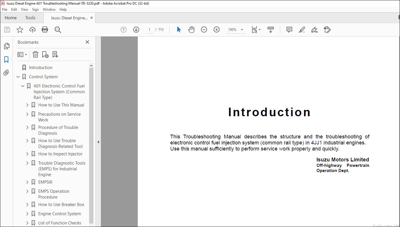
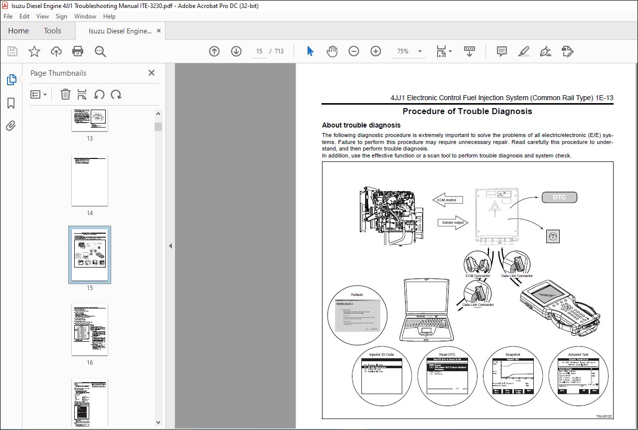
TABLE OF CONTENTS:
Isuzu Diesel Engine 4JJ1 Troubleshooting Manual ITE-3230 – PDF DOWNLOAD
Introduction…………………………………………………………………………………………………………………….. 1
Control System…………………………………………………………………………………………………………………… 3
4JJ1 Electronic Control Fuel Injection System (Common Rail Type)…………………………………………………………………… 3
How to Use This Manual…………………………………………………………………………………………………….. 6
How to use this manual…………………………………………………………………………………………………. 6
Table of abbreviation………………………………………………………………………………………………….. 7
Conversion formula…………………………………………………………………………………………………….. 8
About colors of wirings………………………………………………………………………………………………… 9
About wiring diagrams………………………………………………………………………………………………….. 10
How to read trouble diagnosis section……………………………………………………………………………………. 11
Precautions on Service Work………………………………………………………………………………………………… 13
Electrical system……………………………………………………………………………………………………… 13
Fuel injection system………………………………………………………………………………………………….. 13
Procedure of Trouble Diagnosis……………………………………………………………………………………………… 15
About trouble diagnosis………………………………………………………………………………………………… 15
Trouble diagnostic procedure……………………………………………………………………………………………. 16
Interview…………………………………………………………………………………………………………….. 17
Pre-inspection………………………………………………………………………………………………………… 19
Trouble diagnosis……………………………………………………………………………………………………… 19
How to read DTC……………………………………………………………………………………………………….. 20
Confirmation after repair………………………………………………………………………………………………. 22
List of final check items………………………………………………………………………………………………. 22
How to clear DTC………………………………………………………………………………………………………. 23
Trouble diagnosis with scan tool………………………………………………………………………………………… 24
How to Use Trouble Diagnosis-Related Tool……………………………………………………………………………………. 29
Function of service tools………………………………………………………………………………………………. 29
Tech2………………………………………………………………………………………………………………… 29
Tech2 data reference value……………………………………………………………………………………………… 52
Rewriting of Q adjust correction data by Tech2……………………………………………………………………………. 65
Injector ID code (No. 1 cylinder – No. 6 cylinder or No. 4 cylinder) registration setting using Tech2…………………………… 72
ID code upload (Tech2)…………………………………………………………………………………………………. 80
ID code download (ECM)…………………………………………………………………………………………………. 84
TIS2000………………………………………………………………………………………………………………. 90
How to Inspect Injector…………………………………………………………………………………………………….100
Injector balance test (Tech2, EMPSIII)……………………………………………………………………………………100
Trouble Diagnostic Tools (EMPS) for Industrial Engine………………………………………………………………………….101
Introduction…………………………………………………………………………………………………………..101
List of functions of EMPS……………………………………………………………………………………………….101
Cautions………………………………………………………………………………………………………………102
EMPS Component Parts……………………………………………………………………………………………………104
ECM (hardware) compatibility…………………………………………………………………………………………….105
ECM Variation………………………………………………………………………………………………………….105
System Requirements for EMPS Software (Recommended)………………………………………………………………………..105
EMPS (software) Setup Procedure………………………………………………………………………………………….106
EMPSIII…………………………………………………………………………………………………………………..109
EMPSIII connection……………………………………………………………………………………………………..109
EMPSIII screen display………………………………………………………………………………………………….112
EMPS Operation Procedure……………………………………………………………………………………………………115
1. Preparation…………………………………………………………………………………………………………115
2. ECM Reflash…………………………………………………………………………………………………………118
3. Injector Replacement…………………………………………………………………………………………………137
4. Replace ECM (Same Model)……………………………………………………………………………………………..151
5. Factory Setting……………………………………………………………………………………………………..176
6. Recover Point……………………………………………………………………………………………………….187
7. Error Messages………………………………………………………………………………………………………189
8. Error Code List……………………………………………………………………………………………………..196
How to Use Breaker Box……………………………………………………………………………………………………..206
Breaker box inspection procedure…………………………………………………………………………………………206
Engine Control System………………………………………………………………………………………………………209
Description of function and operation for engine control (common rail) system…………………………………………………209
Engine control module (ECM)……………………………………………………………………………………………..224
Engine component location diagram………………………………………………………………………………………..226
Wiring diagram of engine control module (ECM)……………………………………………………………………………..239
Pin arrangement of engine control module (ECM)…………………………………………………………………………….244
Circuit diagram………………………………………………………………………………………………………..258
Engine harness location…………………………………………………………………………………………………272
Connector list…………………………………………………………………………………………………………276
List of Function Checks…………………………………………………………………………………………………….279
List of function checks…………………………………………………………………………………………………279
OBD system check……………………………………………………………………………………………………….280
Diagnosis lamp illumination circuit system check…………………………………………………………………………..282
Diagnosis lamp blinking circuit system check………………………………………………………………………………284
Scan tool power supply circuit system check (Tech2)………………………………………………………………………..287
Scan tool power supply circuit system check (EMPSIII)………………………………………………………………………289
Scan tool communication circuit system check………………………………………………………………………………291
Starting circuit system check……………………………………………………………………………………………294
Starting system check…………………………………………………………………………………………………..299
Fuel system check………………………………………………………………………………………………………302
Intake system check…………………………………………………………………………………………………….306
Exhaust system check……………………………………………………………………………………………………306
EGR control system check………………………………………………………………………………………………..307
QOS system check……………………………………………………………………………………………………….310
List of Diagnostic Trouble Codes…………………………………………………………………………………………….315
List of diagnostic trouble codes…………………………………………………………………………………………315
DTC: P0087 (Flash code 227) Common rail low pressure fault (No pressure feed in supply pump)……………………………………334
DTC: P0088 (Flash code 118) Common rail pressure is abnormally high (1st or 2nd stage)…………………………………………344
DTC: P0089 (Flash code 151) Common rail pressure fault (Excessive pressure feed in supply pump)…………………………………350
DTC: P0090 (Flash code 247) SCV drive system open circuit, +B short or ground short……………………………………………355
DTC: P0107 (Flash code 71) Barometric pressure sensor circuit input is low (open circuit or ground short)………………………..361
DTC: P0108 (Flash code 71) Barometric pressure sensor circuit input is high (+5V short)………………………………………..367
DTC: P0112 (Flash code 22) Intake air temperature sensor fault (low voltage fault, GND short, short circuit)……………………..373
DTC: P0113 (Flash code 22) Intake air temperature sensor fault (high voltage fault, open circuit or short to power supply circuit)….379
DTC: P0117 (Flash code 23) Engine coolant temperature sensor fault (low voltage fault, GND short, short circuit)………………….386
DTC: P0118 (Flash code 23) Engine coolant temperature sensor input is high (open circuit or short to power supply)………………..392
DTC: P0182 (Flash code 211) Fuel temperature sensor fault (low voltage fault, GND short)……………………………………….400
DTC: P0183 (Flash code 211) Fuel temperature sensor fault (high voltage fault, open circuit or short to power supply circuit)………406
DTC: P0192 (Flash code 245) Common rail pressure sensor fault (low voltage fault, short circuit)………………………………..414
DTC: P0193 (Flash code 245) Common rail pressure sensor fault (high voltage fault)…………………………………………….420
DTC: P0201 (Flash code 271) Open circuit in injection nozzle #1 drive system………………………………………………….426
DTC: P0202 (Flash code 272) Open circuit in injection nozzle #2 drive system………………………………………………….431
DTC: P0203 (Flash code 273) Open circuit in injection nozzle #3 drive system………………………………………………….436
DTC: P0204 (Flash code 274) Open circuit in injection nozzle #4 drive system………………………………………………….441
DTC: P0219 (Flash code 543) Overrun………………………………………………………………………………………446
DTC: P0237 (Flash code 32) Boost pressure sensor fault (low voltage fault, open circuit)……………………………………….448
DTC: P0238 (Flash code 32) Boost pressure sensor fault (high voltage fault, short to power supply circuit, ground open circuit)…….455
DTC: P0335 (Flash code 15) Crank sensor fault (no signal)…………………………………………………………………..462
DTC: P0336 (Flash code 15) Crank sensor fault (signal fault)………………………………………………………………..469
DTC: P0340 (Flash code 14) Cam sensor fault (no signal)…………………………………………………………………….475
DTC: P0341 (Flash code 14) Cam sensor fault (signal fault)………………………………………………………………….482
DTC: P0380 (Flash code 66) Glow relay circuit fault………………………………………………………………………..488
DTC: P0381 (Flash code 67) Glow plug lamp circuit fault…………………………………………………………………….493
DTC: P0487 (Flash code 44) EGR position sensor fault……………………………………………………………………….498
DTC: P0488 (Flash code 45) EGR valve control fault…………………………………………………………………………504
DTC: P0522 (Flash code 294) Engine oil pressure sensor fault (low voltage fault, open circuit, ground short)……………………..510
DTC: P0523 (Flash code 294) Engine oil pressure sensor fault (high voltage fault, short to power supply, ground short)…………….516
DTC: P0601 (Flash code 53) ROM fault……………………………………………………………………………………..524
DTC: P0603 (Flash code 54) EEPROM fault…………………………………………………………………………………..526
DTC: P0606 (Flash code 51) CPU fault……………………………………………………………………………………..528
DTC: P0606 (Flash code 52) CPU monitoring IC fault…………………………………………………………………………530
DTC: P0611 (Flash code 34) Charge circuit fault (bank 1)……………………………………………………………………532
DTC: P0612 (Flash code 34) Charge circuit fault (bank 2)……………………………………………………………………535
DTC: P0615 (Flash code 19) Starter cut relay circuit fault………………………………………………………………….538
DTC: P0650 (Flash code 77) Diagnosis lamp circuit fault…………………………………………………………………….543
DTC: P1093 (Flash code 227) No pump pressure feed………………………………………………………………………….548
DTC: P1095 (Flash code 225) Pressure limiter open………………………………………………………………………….559
DTC: P1112 (Flash code 295) Boost temperature sensor fault (low voltage fault, ground short)……………………………………570
DTC: P1113 (Flash code 295) Boost temperature sensor fault (high voltage fault, open circuit, short to power supply circuit)……….577
DTC: P1173 (Flash code 542) Overheat……………………………………………………………………………………..584
DTC: P1225 (Flash code 31) Idle UP/DOWN switch fault……………………………………………………………………….589
DTC: P1261 (Flash code 158) Injection nozzle common 1 drive system fault……………………………………………………..593
DTC: P1262 (Flash code 159) Injection nozzle common 2 drive system fault……………………………………………………..600
DTC: P1271 (Flash code 24) Accelerator sensor 1-2 comparison fault…………………………………………………………..607
DTC: P1277 (Flash code 24) Accelerator sensor 1 fault (low voltage fault)…………………………………………………….613
DTC: P1278 (Flash code 24) Accelerator sensor 1 fault (high voltage fault)……………………………………………………618
DTC: P1282 (Flash code 24) Accelerator sensor 2 fault (low voltage fault)…………………………………………………….623
DTC: P1283 (Flash code 24) Accelerator sensor 2 fault (high voltage fault)……………………………………………………628
DTC: P1345 (Flash code 16) Cam sensor out of phase…………………………………………………………………………633
DTC: P1625 (Flash code 416) Main relay fault………………………………………………………………………………638
DTC: P1630 (Flash code 36) A/D conversion fault……………………………………………………………………………644
DTC: P1631 (Flash code 55) Voltage fault in 5V power supply 1……………………………………………………………….646
DTC: P1632 (Flash code 55) Voltage fault in 5V power supply 2……………………………………………………………….650
DTC: P1633 (Flash code 55) Voltage fault in 5V power supply 3……………………………………………………………….654
DTC: P1634 (Flash code 55) Voltage fault in 5V power supply 4……………………………………………………………….658
DTC: P1635 (Flash code 55) Voltage fault in 5V power supply 5……………………………………………………………….662
DTC: U2104 (Flash code 84) CAN Bus fault………………………………………………………………………………….666
DTC: U2106 (Flash code 85) CAN timeout fault………………………………………………………………………………671
List of Trouble Symptom…………………………………………………………………………………………………….676
List of trouble symptom…………………………………………………………………………………………………676
Engine start failure……………………………………………………………………………………………………677
Engine stall…………………………………………………………………………………………………………..685
Engine hunting, rough idling…………………………………………………………………………………………….690
Engine output shortage………………………………………………………………………………………………….695
Exhaust gas contains a lot of white smoke…………………………………………………………………………………699
Exhaust gas contains a lot of black smoke…………………………………………………………………………………702
Noise…………………………………………………………………………………………………………………705
Fuel consumption deteriorates……………………………………………………………………………………………707
Oil consumption deteriorates…………………………………………………………………………………………….710
Special Tool………………………………………………………………………………………………………………712
List of special tool……………………………………………………………………………………………………712
More products