$45
John Deere DB60 Planters Installation Instructions Manual A109654D - PDF DOWNLOAD
John Deere DB60 Planters Installation Instructions Manual A109654D - PDF DOWNLOAD
FILE DETAILS:
John Deere DB60 Planters Installation Instructions Manual A109654D - PDF DOWNLOAD
Language :English
Pages :268
Downloadable : Yes
File Type : PDF
IMAGES PREVIEW OF THE MANUAL:
DESCRIPTION:
John Deere DB60 Planters Installation Instructions Manual A109654D - PDF DOWNLOAD
Individual Row Hydraulic
Downforce for DB60
Planters
Introduction IMPORTANT:
- Read through this instruction thoroughly and familiarize yourself with the machine before performing the procedure. Do not skip steps or perform them out of order.
- The acronym FWD stands for: Frame Weight Distribution. The graphics shown in this procedure have parts removed for clarity. Right-hand and left-hand sides are determined by facing in the direction of forward travel.
- This instruction demonstrates the proper procedure for removing the existing pneumatic downforce system and installing the supplied hydraulic downforce system on the following planters.
• DB60: 24R30, 36R20, 47R15, 48R15
General
Face-Seal-Fitting Assembly and Installation—All Pressure Applications
Face-Seal O-Ring to Stud End Installation
1. Inspect the fitting surfaces. They must be free of dirt and/or defects.
2. Inspect the O-ring. It must be free of damage and/or defects.
3. Lubricate O-rings using system oil, and install into groove.
4. Push O-ring into groove so O-ring is not displaced during assembly.
5. Index angle fittings and tighten by hand pressing joint together to insure O-ring remains in place. 6. Tighten fitting or nut to torque value shown on the chart per dash size stamped on the fitting. DO NOT allow hoses to twist when tightening fittings.
Face-Seal Adjustable Stud End O-Ring Installation
1. Back off the lock nut and washer to full exposed turned down section of the fitting.
2. Install a thimble over the fitting threads to protect the O-ring from nicks.
3. Slide the O-ring over the thimble into the turned down section of the fitting.
4. Remove thimble
Face-Seal Straight Stud End O-Ring Installation
1. Install a thimble over the fitting threads to protect the
O-ring from nicks.
2. Slide the O-ring over the thimble into the turned down section of the fitting.
3. Remove thimble.
Fitting Installation
1. Install fitting by hand until snug.
2. Position adjustable fittings by unscrewing the fitting no
more than one turn.
3. Apply assembly torque per table.
Assembly Torque
1. Use one wrench to hold the connector body and one
wrench to tighten nut.
2. For a hydraulic hose, it may be necessary to use three
wrenches to prevent twist; one on the connector body,
one on the nut, and
TABLE OF CONTENTS:
John Deere DB60 Planters Installation Instructions Manual A109654D - PDF DOWNLOAD
Individual Row Hydraulic
Downforce for DB60
Planters
Contents 5
Safety 7
Recognize Safety Information 7
Understand Signal Words 7
Park Machine Safely 7
Follow Safety Instructions 8
Replace Safety Signs 8
Work in Clean Area 8
Avoid High-Pressure Fluids 9
Live With Safety 9
Support Machine Properly 9
Protect Against Noise 10
Use Proper Tools 10
Wear Protective Clothing 10
Use Proper Lifting Equipment 11
Precautions for Welding 11
Welding 12
General 13
Face-Seal-Fitting Assembly and Installation—All Pressure Applications 13
Metric Face Seal and O-Ring Stud End Fitting Torque Chart—Standard Pressures 14
SAE Face Seal and O-Ring Stud End Fitting Torque Chart—Standard Pressures 15
Service Recommendations For Flare-Type Tube Fittings 16
Service Recommendations For SAE Series Four Bolt Flange Fittings 17
Service Recommendations for Metric Series Four Bolt Flange Fitting 18
Unified Inch Bolt and Screw Torque Values 19
Metric Bolt and Screw Torque Values 20
Recommendations for Hydraulic Connections 21
Row Unit Updates 24
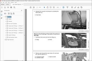
Depressurize the Pneumatic Downforce System 24
Remove the Existing Pneumatic Downforce Springs 25
Replace the Parallel Arm Hardware 26
BA33641 — Install the Actuators 28
BA33646 — Install the ExactEmerge™ Row Unit Harness 32
BA33647 — Install the MaxEmerge™ 5e Row Unit Harness 34
BA32946 and BA33294 — Remove and Install the Downforce Sensor 38
BA33644 — Install the Safety Decals 39
BA33367 — Install the Priority Valve (Planter Power Generation) 40
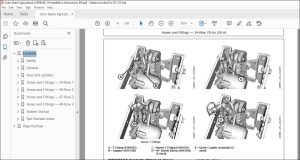
Hoses and Fittings — 24-Row 76 cm (30 in) 42
BA33370 and BA33378 — Install the Actuator Fittings 42
BA33366 — Install the Combination Valve Block 43
BA33374, BA33375, BA33377 — Install the Actuator Fittings 45
BA33376 — Install the Actuator Fittings 46
BA33385 — Install the Supply Hoses (Tractor Power Generation without Frame Weight Distribution) 48
BA33386 — Install the Supply Hoses (Planter Power Generation without Frame Weight Distribution) 53
BA33387 — Install the Supply Hoses (Tractor Power Generation with Frame Weight Distribution) 66
BA33388 — Install the Supply Hoses (Planter Power Generation with Frame Weight Distribution) 69
BA33389 — Install the Row Unit Hoses 78
Hoses and Fittings — 36-Row 51 cm (20 in) 86
BA33370 and BA33378 — Install the Actuator Fittings 86
BA33366 — Install the Combination Valve Block 87
BA33374, BA33375, BA33377 — Install the Actuator Fittings 89
BA33376 — Install the Actuator Fittings 90
BA33385 — Install the Supply Hoses (Tractor Power Generation without Frame Weight Distribution) 92
BA33386 — Install the Supply Hoses (Planter Power Generation without Frame Weight Distribution) 97
BA33387 — Install the Supply Hoses (Tractor Power Generation with Frame Weight Distribution) 110
BA33388 — Install the Supply Hoses (Planter Power Generation with Frame Weight Distribution) 113
BA33390 — Install the Row Unit Hoses 122
Hoses and Fittings — 47-Row 38 cm (15 in) 135
BA33370 and BA33378 — Install the Actuator Fittings 135
BA33366 — Install the Combination Valve Block 136
BA33374, BA33375, BA33377 — Install the Actuator Fittings 138
BA33376 — Install the Actuator Fittings 139
BA33385 — Install the Supply Hoses (Tractor Power Generation without Frame Weight Distribution) 141
BA33386 — Install the Supply Hoses (Planter Power Generation without Frame Weight Distribution) 146
BA33387 — Install the Supply Hoses (Tractor Power Generation with Frame Weight Distribution) 159
BA33388 — Install the Supply Hoses (Planter Power Generation with Frame Weight Distribution) 162
BA33391 — Install the Row Unit Hoses 171
Hoses and Fittings — 48-Row 38 cm (15 in) 185
BA33370 and BA33378 — Install the Actuator Fittings 185
BA33366 — Install the Combination Valve Block 186
BA33374, BA33375, BA33377 — Install the Actuator Fittings 188
BA33376 — Install the Actuator Fittings 189
BA33385 — Install the Supply Hoses (Tractor Power Generation without Frame Weight Distribution) 191
BA33386 — Install the Supply Hoses (Planter Power Generation without Frame Weight Distribution) 196
BA33387 — Install the Supply Hoses (Tractor Power Generation with Frame Weight Distribution) 209
BA33388 — Install the Supply Hoses (Planter Power Generation with Frame Weight Distribution) 212
BA33392 — Install the Row Unit Hoses 221
System Startup 235
IRHD Configuration Setup 235
Parallel Arm Setup 237
Gauge Wheel Downforce Setup 244
Individual Row Hydraulic Downforce (IRHD) Initial Flush and Test 245
Valve Test (IRHD System Only) 247
Valve Flush Test (IRHD System Only) 248
Air Purge Test (IRHD System Only) 250
Accumulator Test (IRHD System Only) 251
Part Number Index 252
Adapters 252
Connectors 253
Elbows 254
Plugs 258
Quick Couplers 259
Reducers 260
T-Fittings 261
Unions 264
Brackets 265
Page Number 5
Section 05 7
Section 10 13
Section 15 24
Section 20 42
Section 25 86
Section 30 135
Section 35 185
Section 40 235
Section 45 252
S.M 8/3/2025
More products