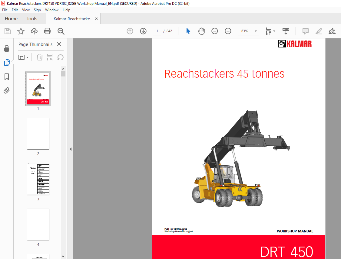
Starting from:
$45
Kalmar DRT 450 Reachstackers 45 Tonnes Workshop Manual VDRT02.02GB – PDF DOWNLOAD
Kalmar DRT 450 Reachstackers 45 Tonnes Workshop Manual VDRT02.02GB – PDF DOWNLOAD
FILE DETAILS:
Kalmar DRT 450 Reachstackers 45 Tonnes Workshop Manual VDRT02.02GB – PDF DOWNLOAD
Language : English
Pages : 842
Downloadable : Yes
File Type : PDF
TABLE OF CONTENTS:
Kalmar DRT 450 Reachstackers 45 Tonnes Workshop Manual VDRT02.02GB – PDF DOWNLOAD
A Foreword.............................................................  5
	A Foreword.........................................................  7
		 About the Workshop Manual.....................................  7
		 Reading instructions..........................................  8
		 About the documentation....................................... 16
		 Feedback...................................................... 17
B Safety............................................................... 19
	B Safety........................................................... 21
		 General safety information.................................... 21
		 Safety instructions........................................... 22
		 Environment................................................... 37
C Preventive maintenance............................................... 39
	C Preventive maintenance........................................... 39
0 Complete machine..................................................... 41
	0 Complete machine................................................. 43
1 Engine............................................................... 49
	1 Engine........................................................... 51
		1.1 Controls and instruments................................... 67
			1.1.1 Ignition............................................. 67
			1.1.2 Accelerator.......................................... 67
		1.2 Fuel system................................................ 68
			1.2.1 Fuel tank............................................ 68
			1.2.2 Sensor fuel level.................................... 68
			1.2.5 Make-contact (closing switch) water in fuel.......... 68
		1.6 Air intake and exhaust outlet.............................. 69
			1.6.1 Air cleaning system.................................. 69
			1.6.3 Exhaust system....................................... 69
			1.6.4 Intercooler.......................................... 70
		1.7 Cooling system............................................. 71
			1.7.4 Radiator and expansion tank.......................... 72
			1.7.5 Cooling fan.......................................... 73
			1.7.7 Coolant.............................................. 74
		1.9 Control system, engine..................................... 78
			1.9.1 Engine control unit.................................. 78
		1.11 Start/stop................................................ 79
			1.11.1 Starter motor....................................... 79
			1.11.2 Stopping device..................................... 79
2 Transmission......................................................... 81
	2 Transmission..................................................... 83
		2.1 Controls and instruments................................... 89
			2.1.1 Gear selector and multi-function lever............... 89
		2.2 Torque converter/Clutch system............................. 90
			2.2.1 Flex plates.......................................... 90
		2.6 Lubrication system......................................... 93
			2.6.3 Oil cooler........................................... 96
		2.7 Cooling system............................................. 98
			2.7.3 Oil cooler........................................... 98
		2.8 Control system, transmission............................... 99
			2.8.1 Transmission control unit............................ 99
			2.8.2 Break contact (opening switch) declutch.............. 99
			2.8.3 Transmission cable harness........................... 99
3 Power transmission...................................................101
	3 Power transmission...............................................103
		3.2 Propeller shaft............................................103
		3.3 Drive axle.................................................104
4 Brakes...............................................................109
	4 Brakes...........................................................111
		4.1 Controls and instruments...................................111
			4.1.1 Brake pedal..........................................111
		4.3 Power-assisted brake system................................113
			4.3.1 Brake oil pump.......................................114
			4.3.2 Brake oil filter.....................................118
			4.3.3 Accumulator charging valve...........................119
			4.3.4 Accumulator..........................................122
			4.3.5 Brake valve..........................................126
			4.3.6 Drive axle block.....................................130
			4.3.7 Break contact (opening switch) brake oil pressure....131
			4.3.8 Make-contact (closing switch) brake lights...........133
			4.3.9 Wheel brakes.........................................134
			4.3.10 Pipes and hoses.....................................137
		4.5 Parking brake system.......................................138
			4.5.1 Brake oil pump.......................................139
			4.5.2 Brake oil filter.....................................139
			4.5.3 Solenoid valve parking brake.........................139
			4.5.4 Parking brake unit...................................140
			4.5.5 Break contact (opening switch) parking brake.........144
			4.5.6 Pipes and hoses......................................144
		4.8 Temperature control, cleaning and oil brake system.........145
			4.8.1 Brake oil tank.......................................146
			4.8.3 Brake oil pump.......................................146
			4.8.4 Accumulator charging valve...........................146
			4.8.5 Drive axle block.....................................146
			4.8.6 Wheel brakes.........................................146
			4.8.7 Oil cooler...........................................147
			4.8.8 Cooling fan..........................................148
			4.8.9 Thermal bypass valve.................................148
			4.8.10 Sensor, oil temperature brake system................149
			4.8.11 Breather filter.....................................150
			4.8.12 Brake oil filter....................................151
			4.8.13 Pipes and hoses.....................................152
			4.8.14 Oil, brake system...................................152
5 Steering.............................................................155
	5 Steering.........................................................157
		5.2 Power assisted system......................................157
			5.2.1 Hydraulic oil pump...................................158
			5.2.2 Priority valve.......................................158
			5.2.3 Steering valve.......................................162
			5.2.4 Steering cylinder....................................165
			5.2.5 Steering axle cradle.................................167
			5.2.6 Link arm.............................................168
			5.2.7 Wheel spindle........................................168
			5.2.8 Wheel hub............................................168
			5.2.13 Pipes and hoses.....................................168
			5.2.21 Valve block servo pressure..........................168
6 Suspension...........................................................169
	6 Suspension.......................................................171
		6.2 Suspension.................................................171
			6.2.1 Steering axle cradle.................................173
			6.2.2 Wheel spindle........................................175
			6.2.3 Wheel hub............................................179
		6.3 Tyres and rims.............................................184
			6.3.1 Tyres................................................186
			6.3.2 Rim..................................................187
			6.3.3 Nut, washer and clamp................................188
7 Load handling........................................................191
	7 Load handling....................................................193
		7.1 Controls and instruments...................................194
			7.1.1 Control lever........................................194
			7.1.2 Switch, lock twistlocks..............................195
		7.2 Lift and lower.............................................196
			7.2.1 Hydraulic oil pump...................................199
			7.2.2 Servo filter.........................................199
			7.2.4 Accumulator servo circuit............................200
			7.2.5 Control valve lift, lower and extension..............202
			7.2.7 Valve block lift cylinder............................203
			7.2.8 Lift cylinder........................................207
			7.2.9 Sensor, hydraulic pressure lift cylinder.............211
			7.2.10 Lift boom...........................................214
			7.2.11 Sensor boom angle...................................214
			7.2.12 Pipes and hoses.....................................214
			7.2.17 Valve block servo pressure..........................215
		7.3 Extension..................................................216
			7.3.1 Hydraulic oil pump...................................219
			7.3.2 Servo filter.........................................219
			7.3.4 Accumulator servo circuit............................219
			7.3.5 Control valve lift, lower and extension..............219
			7.3.7 Valve block, extension cylinder......................220
			7.3.8 Extension cylinder...................................220
			7.3.10 Lift boom...........................................225
			7.3.11 Sensor boom length..................................227
			7.3.12 Pipes and hoses.....................................227
			7.3.17 Valve block servo pressure..........................227
		7.4 Side shift.................................................228
			7.4.1 Hydraulic oil pump...................................229
			7.4.3 Control valve, attachment............................230
			7.4.5 Side shift cylinder..................................234
			7.4.6 Side shift frame.....................................235
			7.4.7 Main beam, attachment................................238
			7.4.8 Relief valve, attachment.............................239
			7.4.9 Pipes and hoses......................................239
			7.4.11 Valve block servo pressure..........................239
		7.5 Spreading (positioning)....................................240
			7.5.1 Hydraulic oil pump...................................242
			7.5.3 Control valve, attachment............................242
			7.5.5 Valve block spreader motor...........................243
			7.5.6 Spreading (positioning) motor........................243
			7.5.7 Spreader chains......................................247
			7.5.8 Spreader beam........................................254
			7.5.9 Main beam, attachment................................256
			7.5.10 Position sensor, spreading..........................256
			7.5.11 Relief valve, attachment............................256
			7.5.12 Pipes and hoses.....................................256
			7.5.16 Valve block servo pressure..........................256
		7.6 Rotation...................................................257
			7.6.1 Hydraulic oil pump...................................258
			7.6.3 Control valve, attachment............................259
			7.6.5 Valve block rotation motor...........................260
			7.6.6 Rotation motor unit..................................261
			7.6.7 Rotation bar.........................................264
			7.6.8 Ring gear............................................266
			7.6.9 Side shift frame.....................................267
			7.6.11 Relief valve, attachment............................267
			7.6.12 Pipes and hoses.....................................268
			7.6.14 Valve block servo pressure..........................268
		7.9 Load carrier...............................................269
			7.9.1 Twistlocks...........................................269
		7.10 Other functions...........................................277
			7.10.2 Weight indicator....................................277
			7.10.3 Container counter...................................279
			7.10.4 Synchronised lift...................................281
8 Control system.......................................................283
	8 Control system...................................................285
		8.1 Controls and instruments...................................286
			8.1.10 Error code menu.....................................286
		8.2 Monitoring.................................................289
			8.2.1 Overload system......................................289
			8.2.2 Bypass...............................................292
			8.2.3 Speed limitation.....................................292
		8.4 Diagnostics................................................293
			8.4.1 CAN/POWER............................................295
			8.4.2 LIGHTS...............................................309
			8.4.3 CAB..................................................322
			8.4.4 CLIMATE..............................................330
			8.4.5 HYD..................................................336
			8.4.6 ENGINE...............................................341
			8.4.7 TRANSM...............................................347
			8.4.8 BOOM.................................................354
			8.4.9 ATTACH...............................................361
			8.4.10 OP..................................................373
			8.4.11 EXTRA...............................................377
			8.4.13 RMI.................................................377
		8.5 Setup......................................................378
			8.5.1 Initiation...........................................378
			8.5.2 Calibration..........................................392
9 Frame, body, cab and accessories.....................................399
	9 Frame, body, cab and accessories.................................401
		9.1 Controls and instruments...................................401
			9.1.1 Gear selector and multi-function lever...............406
			9.1.22 Switch, direction indicators........................407
		9.2 Safety and emergency equipment.............................408
			9.2.1 Control breaker......................................408
			9.2.2 Seat belt............................................408
			9.2.3 Fire extinguisher....................................408
			9.2.4 Buzzer...............................................408
		9.3 Seat.......................................................409
			9.3.1 Seat cushion.........................................412
			9.3.2 Back rest cushion....................................413
			9.3.3 Heating coil.........................................413
			9.3.4 Bumper...............................................414
			9.3.5 Air suspension.......................................414
			9.3.6 Mechanical seat adjustment...........................415
			9.3.8 Arm rest.............................................415
			9.3.9 Sensor, operator-in-seat.............................415
		9.4 Heating, ventilation and air conditioning..................417
			9.4.1 Fresh air filter.....................................424
			9.4.2 Fresh air and recirculation damper...................425
			9.4.3 Cabin fan............................................428
			9.4.4 Heat exchanger heat..................................431
			9.4.5 Water valve..........................................434
			9.4.6 Sensor, engine temperature...........................434
			9.4.7 Compressor...........................................435
			9.4.8 Condenser............................................438
			9.4.9 Receiver drier.......................................440
			9.4.10 Pressure switch.....................................440
			9.4.11 Expansion valve.....................................442
			9.4.12 Sensor, temperature refrigerant.....................443
			9.4.13 Heat exchanger, cooling.............................445
			9.4.14 Air distributor.....................................446
			9.4.15 Defroster nozzles...................................447
			9.4.16 Sensor, temperature outlet fan......................448
			9.4.17 Sensor cab temperature..............................449
			9.4.18 Sensor, ambient temperature.........................450
		9.5 Wiper/washer system........................................451
			9.5.1 Wiper front..........................................451
			9.5.2 Wiper roof...........................................451
			9.5.3 Wiper rear...........................................451
			9.5.4 Washer motor and reservoir...........................451
			9.5.5 Wiper motor front....................................452
			9.5.6 Wiper motor roof.....................................453
			9.5.7 Wiper motor rear.....................................454
		9.6 Lighting system............................................455
			9.6.1 Headlights...........................................459
			9.6.2 Running lights.......................................459
			9.6.3 Tail lights..........................................460
			9.6.4 Brake lights.........................................460
			9.6.5 Back-up lights.......................................460
			9.6.6 Direction indicators.................................461
			9.6.7 Flashing hazard lights...............................461
			9.6.8 Revolving beacon.....................................461
			9.6.9 Working lights, cab..................................462
			9.6.10 Work light boom.....................................462
			9.6.11 Working lights, attachment..........................463
			9.6.12 Interior lighting...................................463
		9.7 Signalling system..........................................464
			9.7.1 Horn.................................................466
			9.7.2 Flashing hazard lights...............................466
			9.7.3 Revolving beacon.....................................466
			9.7.4 Warning parking brake................................467
			9.7.5 Back-up alarm........................................467
		9.8 Entertainment and communication............................468
		9.9 Glass/windows/mirrors......................................469
			9.9.1 Windscreen...........................................470
			9.9.2 Side window..........................................473
			9.9.3 Roof window..........................................475
			9.9.4 Rear window..........................................476
			9.9.5 Rear view mirror.....................................476
		9.10 Cab structure and suspension..............................477
			9.10.1 Cab frame...........................................477
			9.10.2 Doors...............................................477
			9.10.3 Cab substructure....................................478
			9.10.4 Sliding cab.........................................478
		9.11 Cab interior..............................................479
			9.11.1 Instrument and control panels.......................479
			9.11.2 Interior fittings, plastic..........................480
			9.11.3 Interior fittings, textile..........................480
			9.11.4 Floor covering......................................480
			9.11.5 Insulation..........................................480
		9.12 Chassis...................................................481
		9.13 Body structure............................................482
			9.13.1 Wings...............................................482
			9.13.2 Hood engine compartment.............................482
			9.13.3 Footsteps and hand rail.............................482
			9.13.4 Counterweights......................................483
		9.15 Paint/coatings............................................484
10 Common hydraulics...................................................485
	10 Common hydraulics...............................................487
		10.2 Safety valves.............................................487
			10.2.1 Accumulator drain valve.............................487
			10.2.2 Relief valve, attachment............................487
			10.2.3 Pipes and hoses.....................................488
			10.2.4 Pressure limiting valve.............................488
		10.3 Tanks and accumulators....................................489
			10.3.1 Tank................................................489
			10.3.2 Pipes and hoses.....................................489
		10.4 Pumps.....................................................490
			10.4.1 Gear pump with fixed displacement...................490
			10.4.2 Axial piston pump with variable displacement........494
			10.4.3 Pipes and hoses.....................................504
		10.5 Hoses, pipes and valves...................................505
			10.5.1 Pipes and hoses.....................................505
			10.5.2 Priority valve......................................505
			10.5.7 Valve block servo pressure..........................506
		10.6 Temperature control, cleaning and hydraulic oil...........509
			10.6.2 Hydraulic oil cooler................................510
			10.6.3 Cooling fan.........................................511
			10.6.4 Sensor hydraulic oil temperature....................511
			10.6.5 Bypass valve, cooler................................513
			10.6.6 Breather filter hydraulic oil tank..................514
			10.6.7 Hydraulic oil filter................................515
			10.6.8 Hydraulic oil.......................................517
			10.6.9 Fine filter hydraulic oil...........................517
			10.6.10 Pipes and hoses....................................518
		10.7 Other.....................................................519
			10.7.1 Hydraulic cylinders.................................519
11 Common electrics....................................................529
	11 Common electrics................................................531
		11.2 Electric protection.......................................531
			11.2.1 Battery disconnector................................531
			11.2.2 Fuses...............................................531
			11.2.3 Control breaker.....................................531
		11.3 Batteries.................................................532
			11.3.1 Start battery.......................................532
		11.4 Alternator................................................534
			11.4.1 Alternator..........................................534
		11.5 Distribution of electricity...............................535
			11.5.1 Voltage feed........................................535
			11.5.2 Electronic box......................................542
			11.5.3 Control units.......................................544
			11.5.5 Cable harness.......................................553
		11.6 Communication.............................................560
			11.6.1 CAN bus.............................................560
			11.6.2 Redundant CAN bus...................................562
			11.6.3 CAN bus drive-train.................................564
			11.6.4 Communication between PC and machine................565
D Error codes..........................................................567
	D Error codes......................................................569
		 Engine........................................................574
		 Transmission..................................................618
		 Control system................................................653
E Schematics...........................................................675
	E Schematics.......................................................677
		 Common hydraulics.............................................677
		 Common electrics..............................................682
			A50001.0100................................................687
				0 | Wiring DRFC 400-450................................687
				0.0_1 | Wiring Cross References........................688
				0.0_2 | Wiring Cross References........................689
				0.0_3 | Wiring Cross References Opt....................690
				0.0_4 | Wiring Cross References Att....................691
				0.0_5 | Wiring Cross References Att....................692
				0.0_6 | Wiring Cross References Att Combi..............693
				1.0_1 | Wiring Motor Volvo 1240&1250...................694
				1.0_2 | Wiring Motor Cummins...........................695
				1.0_3 | Wiring Motor Cummins...........................696
				1.0_4 | Wiring Motor Volvo D13.........................697
				1.1_1 | Wiring Drivetrain..............................698
				2.0_1 | Wiring Dana TE 32000...........................699
				2.0_2 | Wiring Dana TE 32000...........................700
				2.0_3 | Wiring Dana TE 32000...........................701
				2.0_1A1 | Wiring Dana TE 32000FF.......................702
				2.0_1A2 | Wiring Dana TE 32000FF.......................703
				2.0_1A3 | Wiring Dana TE 32000FF.......................704
				2.0_1B1 | Wiring diagram gear ZF.......................705
				2.1_1 | Wiring Drivetrain..............................706
				4.0_1 | Wiring Brakes..................................707
				4.0_2 | Wiring Brakes..................................708
				5.2_1 +CAB | Wiring Micro lever/wheel..................709
				5.2_2 | Wiring Micro lever/wheel.......................710
				5.2_3 | Wiring Micro lever/wheel and Combi Att.........711
				5.2_4 | Wiring Micro lever/wheel and Combi Att.........712
				7.1_1 | Wiring Joystick................................713
				7.2_1 +CHASSIS | Wiring Boom Up/Down...................714
				7.3_1 | Wiring Boom in/out.............................715
				7.5_1 +ATTACHMENT | Wiring Spreading Valves............716
				7.5_2 | Wiring Spreading Auto..........................717
				7.5_3 | Wiring Spreading Sensors.......................718
				7.6_1 | Wiring Rotation................................719
				7.7_1 | Wiring Tilt lock...............................720
				7.7_2 | Wiring Tilt + Levelling........................721
				7.7_3 | Wiring Tilt + Levelling........................722
				7.9_1 +ATTACHMENT | Wiring Twistlock...................723
				7.9_2 | Wiring Twistlock...............................724
				7.9_3 +CAB | Wiring Combi Att..........................725
				7.9_4 +ATTACHMENT | Wiring Combi Att...................726
				7.9_5 +ATTACHMENT | Wiring Combi Att...................727
				7.9_6 +ATTACHMENT | Wiring Combi Att...................728
				7.9_7 +ATTACHMENT | Wiring Combi Att...................729
				7.9_8 +ATTACHMENT | Wiring Combi Att...................730
				7.9_9 +ATTACHMENT | Wiring Combi Att...................731
				7.9_10 +ATTACHMENT | Wiring Combi Att..................732
				7.9_11 +ATTACHMENT | Wiring Combi Att..................733
				7.9_12 +ATTACHMENT | Wiring Combi Att..................734
				7.9_13 +ATTACHMENT | Wiring Combi Att..................735
				7.9_14 +ATTACHMENT | Wiring Combi Att..................736
				7.9_15 | Wiring Over Height............................737
				7.9_16 | Wiring Over Height............................738
				7.9_17 | Wiring Combi Att..............................739
				7.9_18 | Wiring Fork attachment........................740
				7.10_1 | Wiring Hyd Support jacks......................741
				7.10_2 | Wiring Hyd Support jacks......................742
				7.10_3 | Wiring Printer................................743
				8.2_1 +CHASSIS | Wiring OP + Scale.....................744
				8.2_2 +CHASSIS | Wiring OP + Scale.....................745
				8.2_3 | Wiring Override................................746
				8.2_4 | Wiring RMI.....................................747
				9.1_1 | Wiring OPT Sensors Instr.......................748
				9.1_2 | Wiring Option..................................749
				9.1_3 | Wiring Option..................................750
				9.1_4 | Wiring Sensors Instr...........................751
				9.1_5 | Wiring Option Cabin............................752
				9.1_6 | Wiring Option, Boom nose.......................753
				9.1_7 | Wiring Option..................................754
				9.3_1 +CAB | Wiring Cab Seat OPT.......................755
				9.3_2 +CAB | Wiring Cab Seat OPT.......................756
				9.4_1 +CAB | Wiring Climate Control....................757
				9.4_2 +CAB | Wiring Climate Control....................758
				9.4_3 | Wiring Climate Control.........................759
				9.5_1 +CAB | Wiring Wiper function.....................760
				9.6_1 +CAB | Wiring Work Light.........................761
				9.6_2 +ATTACHMENT | Wiring Opt. Work Light Att.........762
				9.6_3 | Wiring OPT Work Light Boom.....................763
				9.6_5 | Wiring Lights..................................764
				9.6_6 | Wiring Lights..................................765
				9.6_7 | Wiring Lights..................................766
				9.6_8 | Wiring Lights..................................767
				9.6_9 | Wiring Step In Light...........................768
				9.6_10 | Wiring Opt. Work Light Chassis................769
				9.7_1 | Wiring Alarm, Soundsignals.....................770
				9.7_2 | Wiring Alarm, Soundsignals.....................771
				9.7_3 | Wiring Flashing indicator, Hazard..............772
				9.7_4 | Wiring Reverse alarm...........................773
				9.8_1 | Wiring Radio...................................774
				9.9_9 | Wiring Camera..................................775
				9.10_1 | Wiring Sliding/Vertically adjustable Ca.......776
				9.10_2 | Wiring Cab tilt...............................777
				9.14_1 | Wiring Central Lubrication....................778
				10.0_1 | Wiring Hydraulics.............................779
				11.5_1 +CHASSIS | Wiring Power.........................780
				11.5_2 +CAB | Wiring Power.............................781
				11.5_3 +CAB | Wiring Power.............................782
				11.5_4 | Wiring Power..................................783
				11.5_5 | Wiring Power..................................784
				11.5_6 | Wiring Power..................................785
				11.5_7 | Wiring 24V....................................786
				11.5_8 | Wiring 12V + Com. Radio.......................787
				11.5_9 | Wiring Power Att..............................788
				11.5_10 | Wiring Power 230V Inverter...................789
				11.6_3 | Wiring CAN-BUS Opt. chassis KDU...............790
				11.6_4 | Wiring CAN-BUS Att............................791
				11.6_5 | Wiring CAN-BUS Att............................792
				11.6_6 | Wiring CAN-BUS Att............................793
			A58687.0100................................................794
				1.0_1A1................................................794
				1.0_1A2................................................795
				1.0_1B1................................................796
				2.0_1A1................................................797
				2.0_1A2................................................798
			List of Components.........................................799
F Technical data.......................................................817
	F Technical data...................................................819
G Terminology and index................................................833
	G Terminology and index............................................835
		 Terminology...................................................835
		 Index.........................................................837
DESCRIPTION:
Kalmar DRT 450 Reachstackers 45 Tonnes Workshop Manual VDRT02.02GB – PDF DOWNLOAD
About the Workshop Manual:
General:
- Thank you for choosing Cargotec as your machine supplier. We hope
that we’ll meet your expectations.
Conditions:
- The instructions are based on the use of generally available standard
tools. All lifting devices, for example, slings, straps, ratchet blocks,
etc., must meet governing national standards and regulations for lifting
devices. - Cargotec will not accept any responsibility for modifications performed
without permission from Cargotec or if other lifting devices, tools or
work methods are used other than those described in this manual.
About the machine version:
- The information in this publication corresponds to the machine’s design
and appearance at the time of delivery from Cargotec. Due to customizations,
there may be variations and/or deviations. - Cargotec reserves the right to modify specifications and equipment
without prior notice. All information and data in this manual are valid at
the time of publication.
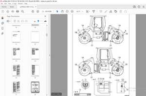
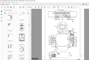
IMAGES PREVIEW OF THE MANUAL:

More products