$36
Komatsu 107E-1 Series Engine Shop Manual SEN00161-28 – PDF DOWNLOAD
Komatsu 107E-1 Series Engine Shop Manual SEN00161-28 – PDF DOWNLOAD
FILE DETAILS:
Komatsu 107E-1 Series Engine Shop Manual SEN00161-28 – PDF DOWNLOAD
Language : English
Pages : 598
Downloadable : Yes
File Type : PDF
Size: 33 MB
IMAGES PREVIEW OF THE MANUAL:
DESCRIPTION:
Komatsu 107E-1 Series Engine Shop Manual SEN00161-28 – PDF DOWNLOAD
The Komatsu 140E-5 Series Diesel Engine Shop Manual SEN00074-16 is a technical reference guide for maintaining, repairing, and overhauling the Komatsu 140E-5 series diesel engine. This engine is commonly used in heavy-duty applications, such as construction equipment, mining vehicles, and marine vessels. The manual is an essential resource for mechanics, technicians, and service personnel responsible for servicing and maintaining these engines.
The shop manual is organized into several sections, each of which covers a specific aspect of the engine. These sections include:
- General Information: This section provides an overview of the engine, including specifications, operating guidelines, and maintenance intervals.
- Inspection and Adjustment: This section provides detailed instructions for inspecting and adjusting engine components, including the fuel injection system, valves, and timing belt.
- Engine Assembly: This section covers the removal and installation of major engine components, such as the cylinder head, crankshaft, and pistons. The manual includes detailed illustrations and specifications to help technicians perform these tasks safely and efficiently.
- Lubrication System: This section provides information on the engine’s lubrication system, including oil pump removal and installation, oil filter replacement, and oil pressure testing.
- Cooling System: This section provides information on the engine’s cooling system, including water pump removal and installation, radiator removal and installation, and thermostat replacement.
- Fuel System: This section covers the engine’s fuel system, including fuel pump removal and installation, fuel injector replacement, and fuel system troubleshooting.
- Air Intake and Exhaust System: This section provides information on the engine’s air intake and exhaust system, including air filter replacement, turbocharger removal and installation, and exhaust manifold removal and installation.
- Electrical System: This section provides information on the engine’s electrical system, including alternator and starter motor removal and installation, as well as troubleshooting procedures for electrical faults.
- Special Tools: This section lists the special tools required for servicing the engine, including part numbers and illustrations.
The Komatsu 140E-5 Series Diesel Engine Shop Manual SEN00074-16 is an essential resource for maintaining and repairing these engines. It provides a comprehensive guide to servicing the engine and includes detailed instructions, specifications, and illustrations to help technicians perform tasks accurately and safely. The manual is a valuable tool for ensuring that the Komatsu 140E-5 series diesel engine continues to operate at peak performance, with maximum efficiency and reliability over its long service life.
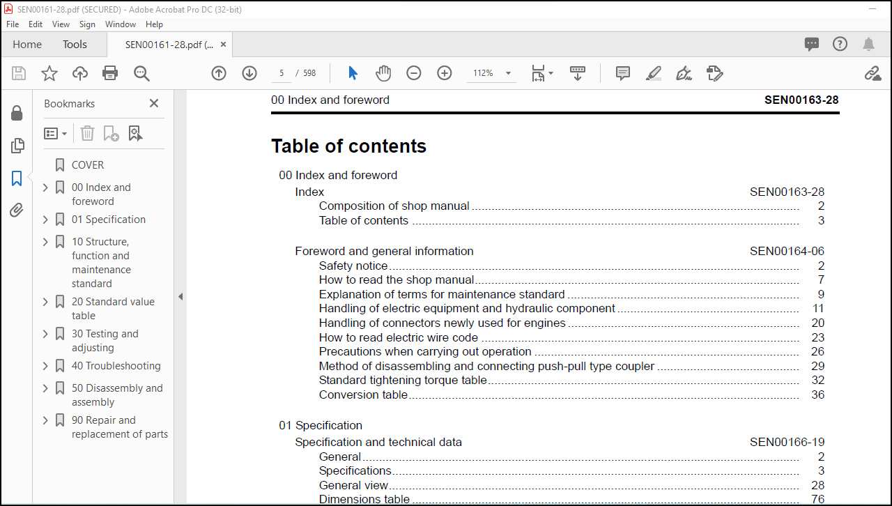
TABLE OF CONTENTS:
Komatsu 107E-1 Series Engine Shop Manual SEN00161-28 – PDF DOWNLOAD
OD Index and foreword
Index
Composition of shop manual
Table of contents
Foreword and general information
Safety notice
How to read the shop manual
Explanation of terms for maintenance standard
Handling of electric equipment and hydraulic component
Handling of connectors newly used for engines
How to read electric wire code
Precautions when can’ying out operation
Method of disassembling and connecting push-pull type coupler
Standard tightening torque table
Conversion table
01 Specification
Specification and technical data
General
Specrfications
General vrew
Dimensions table
Engine performance curves
10 Structure. function and maintenance standard
Structure. function and maintenance standard
Intake system _
Exhaust system
Lubricating oii system
Cooling system
Fuel system
Fuel supply pump
CRI system
Turbocharger
Cylinder head
Cylinder block
Crankshaft
Piston. piston ring and piston pin
Connecting rod
Vibration damper
Timing gear
Camshaft
Valve and valve guide
Rocker arm. shaft and tappet
Flywheel and flywheel housing
Water pump drive and fan dnve
Water pump
Thermostat
Alternator
Starting motor
Sensor
Engine controller
Control system
20 Standard value table
Standard service value table 3
Standard value table for testing. adjusting and troubleshooting
Running-in standard and performance test cntena30 Testing and adjusting
Testing and adjusting 3
Testing and adjusting tools list.
Sketches of special tools
Testing boost pressure
Adjustment of valve clearance
Testing compression pressure
Testing blowby pressure
Testing engine oil pressure
Handling fuel system parts
Releasing remaining pressure in fuel system
Testing fuel pressure
Reduced cylinder mode operation
No-injection cranking
Testing fuel delivery. retum and leak amount
Bleeding air from fuel crrcurt
Testing fuel system for leakage
Handling controller high-voltage circuit
Replacing the fan belt40 TroubleshootingGeneral information on troubleshooting 3
Points on troubleshooting
Error and failure code table
Troubleshooting method for open circuit in wiring harness of pressure sensor system
lnfonnation in troubleshooting table
Connection table for connector pin numbers
T- branch box and T— branch adapter table
Troubleshooting of electrical system (E-mode). Part 1 3
E4 Code [111ICA111] Abnormality in engine controller
E-2 Code [115/CA115] Abnormality in engine Ne. Bkup speed sensor
E-S Code [12?JCA122] Charge pressure sensor high error
E-4 Code [123ICA123] Charge pressure sensor low error
E-5 Code [131/CA131] Throttle sensor power supply high error
E-6 Code [132ICA132] Throttle sensor power supply low error
E? Code [144ICA144] Coolant temperature sensor high error
E-8 Code [145!CA145] Coolant temperature sensor low error
E-Q Code [1 531CA153] Charge temperature sensor high error
E-1D Code [151!CA154] Charge temperature sensor low error
E-li Code [155!CA155] Derating of speed by charge temperature high error …-……..
E-12 Code [187!CA187] Sensor power supply 2 low error
E-13 Code [221ICA221] Atompspheric pressure sensor high error
E-14 Code [222JCA222] Atompspheric pressure sensor low error
E-15 Code [227/CA227] Sensor power supply 2 high error
E-lB Code [234!CA234] Engine overspeed
E-l? Code [238!CA2381Abnormallity in Ne speed sensor power supply
E-lB Code [271ICA271] Short circuit in lMVlPCVl
E-19 Code [272!CA272] Disconnection in IMVIPCVI
E-ZD Code [322!CA322] Disconnection. short circuit in injector No. 1
E-21 Code [323!CA323] Disconnection. short circuit in injector No. 5
E-22 Code [324ICA324] Disconnection. short circuit in injector No. 3
E-23 Code [325ICA325] Disconnection. short circuit in injector No. 6
E-24 Code [331/CA331] Disconnection. short circuit in injector No. 2E-25 Code [332/CA332] Disconnection. short circuit in injector No. 4E-26 Code [342/CA342] Calmration error in engine controller dataE-27 Code [351/CA351] Abnormality in injector drive circuitE-28 Code [352!CA352] Sensor power supply 1 low enorE-29 Code [386!CA386] Sensor power supply 1 high enorE-3D Code [428!CA4281Water-in-fuel sensor high errorE-31 Code [429!CA4291Water-in-fuel sensor low errorE-32 Code [431!CA431] Abnormality in idle validation switchE-33 Code [432/CA432] Abnormality in idle validation processing-……-……-….-.Troubleshooting of electrical system (E-mode). Part 2E34 Code [435!CA435] Abnormality in engine ofl pressure swrtchE-35 Code [441/CA441] Abnormally low power supply voltageE-36 Code [442!CA442] Abnormally high power supply voltageE-37 Code [449!CA449] Common rail pressure high error 2E-38 Code [451!CA451] Common rail pressure sensor high errorE-39 Code [452!CA452] Common rail pressure sensor low errorE40 Code [488!CA488] Derating of torque by charge temperature high enor..-E41 Code [553!CA553] Common rail pressure high error 1E42 Code [559!CA559] No-pressure feed 1 by supply pumpE43 Code [689!CA689] Abnormality in engine Ne speed sensor…-….-……-…..-E44 Code [731/CA731] Abnormality in engine Bkup speed sensor phase…….-E45 Code [757!CA757] Loss of all data in engine controllerE46 Code [778!CA778] Abnormality in engine Bkup speed sensor……………….E47 Code [1633!CA1633] Abnormality in KOMNEI’E48 Code [2185!CA2185] Throttle sensor power supply high errorE49 Code [21861CA2186] Throttle sensor power supply low errorE-5D Code [2249/CA2249] No-pressure feed 2 by supply pumpE-51 Code [2311ICA2311] Abnon’nafity in IMV solenoid.-….-……-….-……-….-…..-E-52 Code [2555/CA2555] Disconnection in intake air heater relayE-53 Code [2556/CA255B] Short circuit in intake air heater relay….-….-……-….–E-54 Code [—IB@BAZG] Derating of speed by engine oil pressure reduction ..E-55 Code [—IB@BAZK] Engine oil level lowE-56 Code [–lB@BCNS] Engine overheatE-57 Code [A8] Rated Speed Adjustment Volume (Isochronous) High ErrorE-58 Code [A9] Rated Speed Adjustment Volume (Isochronous) Low ErrorE-59 Code [AA] Rated Speed Adjustment Volume (Droop) High Error560 Code [A3] Rated Speed Adjustment Volume (Droop) Low ErrorE»61 Code [AF] Abnormality in KOMNET (CR710 error recognition)E62 Code [b6] Droop Rate Adjustment Volume High ErrorE-63 Code [b7] Droop Rate Adjustment Volume Low ErrorE434 Code [b8] Low Idle Speed Adjustment Volume High ErrorE-65 Code [b9] Low Idle Speed Adjustment Volume Low ErrorE436 Code [bc] Rated Speed Median Adjustment Volume High Error567 Code [b9] Rated Speed Median Adjustment Volume Low Error568 Code [bE] Ramp Trme Adjustment Volume High ErrorE439 Code [bF] Ramp Trme Adjustment Volume Low ErrorTroubleshooting of mechanical system (Smode)Troubleshooting of mechanical system (S-mode)
Method of using troubleshooting charts
S-1 Starting performance is poor
S—2 Engine does not start
S-3 Engine does not pick up smoothly
S-4 Engine stops during operations
S-5 Engine does not rotate smoothly
S-6 Engine lacks output (or lacks power)
S-7 Exhaust smoke is black (Incomplete combustion)
S-8 Oil consumption is excessive (or exhaust smoke is blue)
S-9 Oil becomes contaminated quickly
S-10 Fuel consumption is excessive
S-11 Oil is in coolant (or coolant spurts back or coolant level goes down)
S-12 Oil pressure drops
S-13 Oil level rises (Entry of coolant or fuel)
S-14 Coolant temperature becomes too high (overheating)
S-15 Abnormal noise is made
S-16 Vibration is excessrve
50 Disassembly and assembly
General information on disassembly and assembly
How to read this manual
Coating materials list
Special tools fist
Disassembly and assembly. Part 1
General disassembly of engine
Disassembly and assembly. Part 2
General assembly of engine
90 Repair and replacement of parts
Information related to repair and replacement
Special tool table
Parts related to cylinder head
Repair of cylinder head
Check of valve guide
Replacement of valve seat insert
Vacuum test of valve seat Insert
Grinding of valve
Parts related to cylinder block
Repair of cylinder block
Repair of crankshaft
Replacement of connecting rod bushing
More products