$35
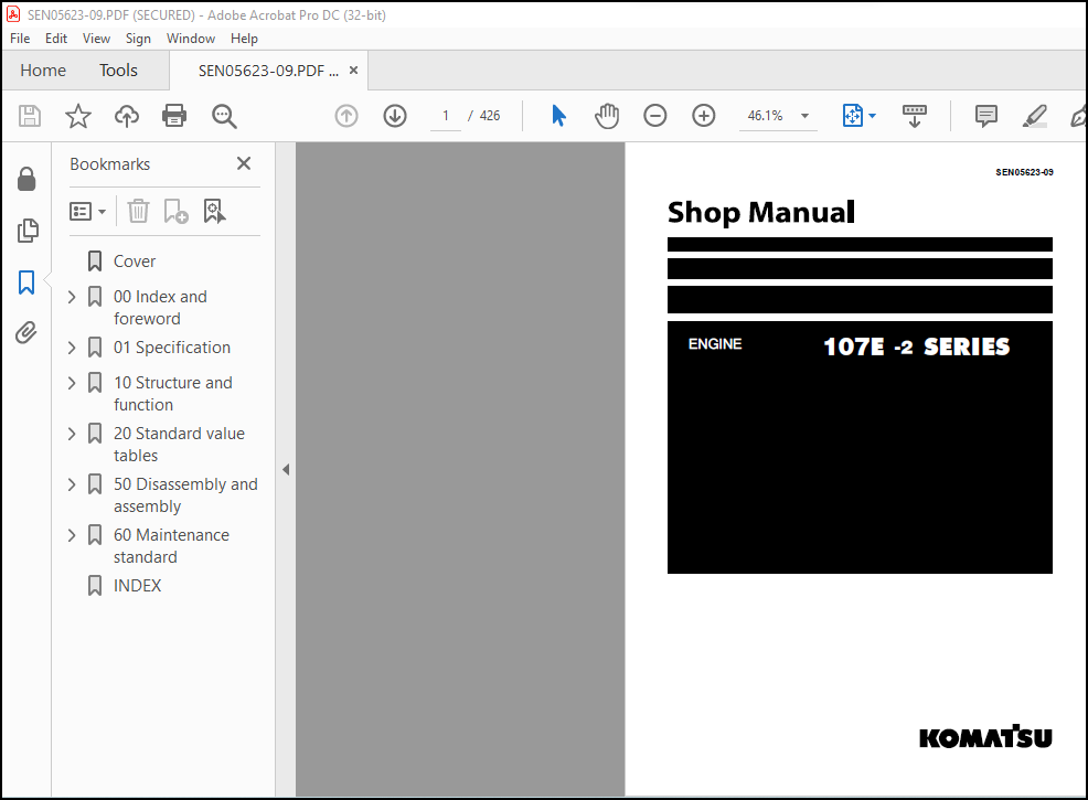
Komatsu 107E -2 SERIES ENGINE Shop Manual(SEN05623-09) – PDF DOWNLOAD
Komatsu 4D98E 4D108 S4D108 SERIES DIESEL ENGINE SHOP MANUAL(WEBM4D9801) – PDF DOWNLOAD
DESCRIPTION:
Komatsu 107E -2 SERIES ENGINE Shop Manual(SEN05623-09) – PDF DOWNLOAD
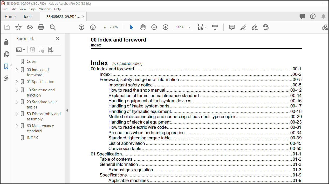
Foreword, safety and general information (ALL-0370-001-A-00-A)
Important safety notice (ALL-1120-012-A-01-A)
• Appropriate servicing and repair are extremely important to ensure safe operation of the machine. The
shop manual describes the effective and safe servicing and repair methods recommended by Komatsu.
Some of these methods require the use of the special tools designed by Komatsu for the specific purpose.
• The symbol markkis used for such matters that require special cautions during the work. The work
indicated by the caution mark should be performed according to the instructions with special attention to
the cautions. Should hazardous situation occur or be anticipated during such work, be sure to keep safe
first and take every necessary measure.
Safety points
• Good arrangement
• Correct work clothes
• Observance of work standard
• Practice of making and checking signals
• Prohibition of operation and handling by
unlicensed workers
• Safety check before starting work
• Wearing protective goggles (for cleaning or
grinding work)
• Wearing shielding goggles and protectors (for
welding work)
• Good physical condition and preparation
• Precautions against work which you are not
used to or you are used to too much
General precautions
kInappropriate handling causes an extreme
danger. Read and understand what is
described in the operation and maintenance
manual before operating the machine. Read
and understand what is described in this
manual before starting the work.
• Before performing any greasing or repairs, read
all the safety labels stuck to the machine. For
the locations of the safety labels and detailed
explanation of precautions, see the operation
and maintenance manual.
• Locate a place in the repair workshop to keep
the tools and removed parts. Always keep the
tools and parts in their correct places. Always
keep the work area clean and make sure that
there is no dirt, water or oil on the floor. Smoke
only in the areas provided for smoking. Never
smoke while working.
• When performing any work, always wear the
safety shoes and helmet. Do not wear loose
work cloths, or clothes with buttons missing.
1. Always wear the protective eyeglasses when
hitting parts with a hammer.
2. Always wear the protective eyeglasses when
grinding parts with a grinder, etc.
• When performing any work with 2 or more
workers, always agree on the working procedure
before starting. While working, always keep
conversations of the work between your fellow
workers and your self on any step of the work.
During the work, hang the warning tag of
“UNDER WORKING” in the operator’s
compartment.
• Only qualified workers must perform the work
and operation which require license or
qualification.
• Keep the tools in good condition. And learn the
correct way to use the tools, and use the proper
ones among them. Before starting the work,
thoroughly check the tools, lift truck, service
vehicle, etc.
• If welding repairs is required, always have a
trained and experienced welder with good
knowledge of welding perform the work. When
performing welding work, always wear welding
gloves, apron, shielding goggles, cap, etc.
• Before starting work, warm up your body
thoroughly to start work under good condition.
• Avoid continuing work for long hours and take
rests with proper intervals to keep your body in
good condition. Take a rest in a specified safe
place.
Preparation
• Before adding oil or making any repairs, place
the machine on a firm and level ground, and
apply the parking brake and chock the wheels or
tracks to prevent the machine from moving.
• Before starting work, lower the work equipment
(blade, ripper, bucket, etc.) to the ground. If it is
not possible to lower the equipment to the
ground, insert the lock pin or use blocks to
prevent the work equipment from falling. And be
sure to lock all the work equipment control levers
and hang a warning tag on them.
• When performing the disassembling or
assembling work, support the machine securely
with blocks, jacks, or stands before starting the
work.
• Remove all of mud and oil from the steps or
other places used to get on and off the machine
completely. Always use the handrails, ladders of
steps when getting on or off the machine. Never
TABLE OF CONTENTS:
Komatsu 107E -2 SERIES ENGINE Shop Manual(SEN05623-09) – PDF DOWNLOAD
Cover……………………………………………………………… 1
00 Index and foreword ………………………………………………. 3
Index …………………………………………………………. 4
Foreword, safety and general information ………………………….. 7
Important safety notice ……………………………………… 7
How to read the shop manual ………………………………….. 14
Explanation of terms for maintenance standard ………………….. 16
Handling equipment of fuel system devices ……………………… 18
Handling of intake system parts ………………………………. 19
Handling of hydraulic equipment ………………………………. 20
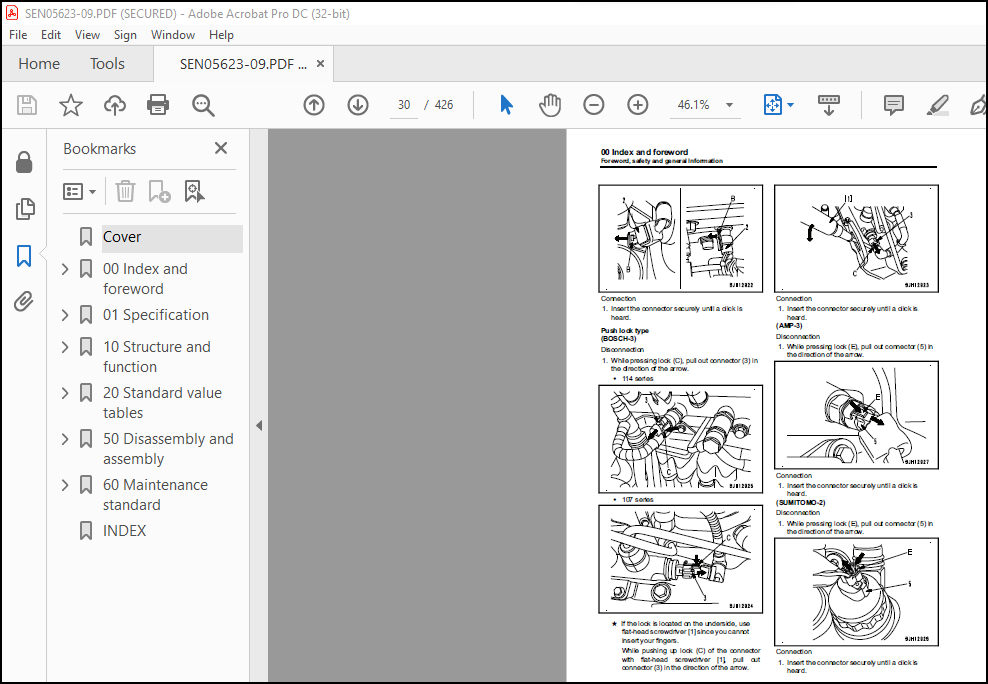
Method of disconnecting and connecting of push-pull type coupler …. 22
Handling of electrical equipment ……………………………… 25
How to read electric wire code ……………………………….. 33
Precautions when performing operation …………………………. 36
Standard tightening torque table ……………………………… 41
List of abbreviation ………………………………………… 47
Conversion table ……………………………………………. 52
01 Specification …………………………………………………… 57
Table of contents ………………………………………………. 58
General information …………………………………………….. 59
Exhaust gas regulation ………………………………………. 59
Specifications …………………………………………………. 65
Applicable machines …………………………………………. 65
Specifications ……………………………………………… 66
General view ……………………………………………….. 76
Engine performance curve ……………………………………..109
10 Structure and function ……………………………………………119
Table of contents ……………………………………………….120
Components layout ……………………………………………….122
Components layout drawing (4D107) ……………………………..122
Components layout drawing (6D107) ……………………………..124
Intake and exhaust system parts …………………………………..126
Intake and exhaust system layout drawing (4D107) ………………..126
Intake and exhaust system layout drawing (6D107) ………………..127
Intake and exhaust system circuit diagram (4D107) ……………….128
Intake and exhaust system circuit diagram (6D107) ……………….130
Air cleaner (4D107) ………………………………………….132
Air cleaner (6D107) ………………………………………….133
VFT (4D107) …………………………………………………135
VGT(6D107) ………………………………………………….139
Aftercooler …………………………………………………147
EGR system piping drawing (4D107) ……………………………..148
EGR system piping drawing (6D107) ……………………………..150
EGR system circuit diagram (4D107) …………………………….152
EGR system circuit diagram (6D107) …………………………….154
EGR valve (4D107) ……………………………………………156
EGR valve (6D107) ……………………………………………158
EGR cooler ………………………………………………….160
Layout of KCCV (4D107) ……………………………………….161
Layout of KCCV (6D107) ……………………………………….164
KCCV ventilator ……………………………………………..166
KDOC muffler (4D107) …………………………………………170
KDPF (6D107) ………………………………………………..172
Engine main body parts …………………………………………..177
Cylinder head ……………………………………………….177
Cylinder block ………………………………………………179
Main moving parts ……………………………………………181
Vibration damper (6D107) ……………………………………..185
Timing gear …………………………………………………186
Front cover …………………………………………………187
Valve system ………………………………………………..188
Flywheel ……………………………………………………191
Lubrication system ………………………………………………193
Lubrication system parts layout drawing (4D107) …………………193
Lubrication system parts layout drawing (6D107) …………………195
Lubrication system circuit diagram (4D107) ……………………..197
Lubrication system circuit diagram (6D107) ……………………..198
Oil pump ……………………………………………………199
Boost oil pump (6D107) ……………………………………….200
Oil filter ………………………………………………….201
Oil cooler ………………………………………………….202
Regulator valve ……………………………………………..203
Safety valve ………………………………………………..204
Oil pan …………………………………………………….205
Fuel system …………………………………………………….206
Fuel system parts layout drawing ………………………………206
Fuel system circuit diagram …………………………………..209
Supply pump …………………………………………………213
Fuel cooler …………………………………………………214
Pre-filter ………………………………………………….215
Main filter …………………………………………………216
Cooling system ………………………………………………….217
Cooling system parts layout drawing ……………………………217
Cooling system circuit diagram (4D107) …………………………218
Cooling system circuit diagram (6D107) …………………………219
Drive pulley ………………………………………………..220
Water pump ………………………………………………….225
Thermostat ………………………………………………….226
Electrical equipment …………………………………………….227
Alternator ………………………………………………….227
Starting motor ………………………………………………235
Intake air heater ……………………………………………239
Engine wiring harness (4D107) …………………………………240
Engine wiring harness (6D107) …………………………………242
Engine controller (4D107) …………………………………….244
Engine controller (6D107) …………………………………….250
Sensor ……………………………………………………..256
20 Standard value tables …………………………………………….273
Table of contents ……………………………………………….274
Standard service value table ……………………………………..275
Standard value table for engine ……………………………….275
Running-in standard and performance test standard ……………….305
50 Disassembly and assembly ………………………………………….315
Table of contents ……………………………………………….316
Related information on disassembly and assembly …………………….317
How to read this manual ………………………………………317
Coating materials list ……………………………………….319
Special tool list ……………………………………………323
Sketch of special tool ……………………………………….325
Disassembly and assembly …………………………………………326
General disassembly of engine …………………………………326
General assembly of engine ……………………………………348
Removal and installation procedure of supply pump unit alone ……..389
Engine front oil seal replacement procedure …………………….393
Engine rear oil seal replacement procedure ……………………..396
60 Maintenance standard ……………………………………………..399
Table of contents ……………………………………………….400
Intake and exhaust system parts …………………………………..401
VFT (4D107) …………………………………………………401
VGT(6D107) ………………………………………………….402
Engine main body parts …………………………………………..403
Cylinder head ……………………………………………….403
Cylinder block ………………………………………………405
Crankshaft ………………………………………………….407
Piston ……………………………………………………..409
Connecting rod ………………………………………………410
Vibration damper (6D107) ……………………………………..412
Timing gear …………………………………………………413
Camshaft ……………………………………………………414
Valve and valve guide ………………………………………..416
Rocker arm ………………………………………………….418
Tappet ……………………………………………………..419
Flywheel ……………………………………………………420
Lubrication system ………………………………………………422
Oil pump ……………………………………………………422
INDEX………………………………………………………………423
IMAGES PREVIEW OF THE MANUAL:
More products