$36
Komatsu 125-5 Series Engine Shop Manual SEN00177-19 – PDF DOWNLOAD
Komatsu 125-5 Series Engine Shop Manual SEN00177-19 – PDF DOWNLOAD
FILE DETAILS:
Komatsu 125-5 Series Engine Shop Manual SEN00177-19 – PDF DOWNLOAD
Language : English
Pages : 666
Downloadable : Yes
File Type : PDF
Size: 43.6 MB
IMAGES PREVIEW OF THE MANUAL:
DESCRIPTION:
Komatsu 125-5 Series Engine Shop Manual SEN00177-19 – PDF DOWNLOAD
The Komatsu 125-5 Series Engine Shop Manual SEN00177-19 is a comprehensive technical guide that provides detailed information on the maintenance, repair, and overhaul of the Komatsu 125-5 series diesel engine. This engine is commonly used in heavy equipment such as excavators, bulldozers, and wheel loaders.
The manual is organized into several sections, each covering specific aspects of the engine:
- General Information: This section provides an overview of the engine, including specifications, maintenance intervals, and general operating guidelines.
- Inspection and Adjustment: This section provides detailed instructions for inspecting and adjusting engine components, such as the fuel injection system, valves, and timing belts.
- Engine Assembly: This section covers the removal and installation of major engine components, including the cylinder head, crankshaft, and pistons. The manual includes detailed illustrations and specifications to help technicians perform these tasks safely and efficiently.
- Lubrication System: This section provides information on the engine’s lubrication system, including oil pump removal and installation, oil filter replacement, and oil pressure testing.
- Cooling System: This section provides information on the engine’s cooling system, including water pump removal and installation, radiator removal and installation, and thermostat replacement.
- Fuel System: This section covers the engine’s fuel system, including fuel pump removal and installation, fuel injector replacement, and fuel system troubleshooting.
- Air Intake and Exhaust System: This section provides information on the engine’s air intake and exhaust system, including air filter replacement, turbocharger removal and installation, and exhaust manifold removal and installation.
- Electrical System: This section provides information on the engine’s electrical system, including alternator and starter motor removal and installation, as well as troubleshooting procedures for electrical faults.
- Special Tools: This section lists the special tools required for servicing the engine, including part numbers and illustrations.
The Komatsu 125-5 Series Engine Shop Manual SEN00177-19 is an essential reference guide for maintaining and repairing the engine. It provides detailed instructions, specifications, and illustrations to help technicians perform tasks accurately and safely. The manual is a valuable tool for ensuring that the Komatsu 125-5 series diesel engine continues to operate at peak performance, with maximum efficiency and reliability over its long service life.
Overall, the Komatsu 125-5 Series Engine Shop Manual SEN00177-19 is an essential guide for technicians working on this engine. The manual covers every aspect of maintenance, repair, and overhaul, making it an indispensable resource for anyone who wants to keep their Komatsu equipment running smoothly and reliably.
TABLE OF CONTENTS:
Komatsu 125-5 Series Engine Shop Manual SEN00177-19 – PDF DOWNLOAD
COVER…………………………………………………………………………. 1
00 Index and foreword…………………………………………………………… 3
Index……………………………………………………………………… 3
Composition of shop manual……………………………………………….. 4
Table of contents……………………………………………………….. 5
Foreword and general information……………………………………………… 11
Safety notice…………………………………………………………… 12
How to read the shop manual………………………………………………. 17
Explanation of terms for maintenance standard………………………………. 19
Handling of electric equipment and hydraulic component………………………. 21
Handling of connectors newly used for engines………………………………. 30
How to read electric wire code……………………………………………. 33
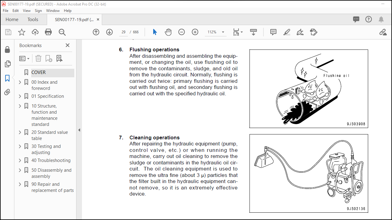
Precautions when carrying out operation……………………………………. 36
Method of disassembling and connecting push-pull type coupler………………… 39
Standard tightening torque table………………………………………….. 42
Conversion table………………………………………………………… 46
01 Specification……………………………………………………………….. 53
Specification and technical data……………………………………………… 53
Outline………………………………………………………………… 54
Specifications………………………………………………………….. 58
General view……………………………………………………………. 74
Weight table…………………………………………………………….110
Engine performance curves…………………………………………………113
10 Structure, function and maintenance standard…………………………………….125
Structure, function and maintenance standard, Part 1…………………………….125
General structure………………………………………………………..128
Air intake and exhaust unit……………………………………………….130
Air cleaner……………………………………………………………..134
Turbocharger…………………………………………………………….136
Aftercooler……………………………………………………………..143
EGR system………………………………………………………………144
Cylinder head……………………………………………………………151
Cylinder block…………………………………………………………..154
Cylinder liner…………………………………………………………..158
Main moving parts………………………………………………………..159
Crankshaft………………………………………………………………161
Camshaft………………………………………………………………..162
Cam follower and push rod…………………………………………………163
Piston, piston ring and piston pin…………………………………………164
Connecting rod…………………………………………………………..166
Flywheel and flywheel housing……………………………………………..167
Vibration damper…………………………………………………………172
Timing gear……………………………………………………………..174
Valve system…………………………………………………………….182
Valve and valve guide…………………………………………………….186
Rocker arm and shaft……………………………………………………..188
Crosshead and guide………………………………………………………189
Structure, function and maintenance standard, Part 2…………………………….191
Lubrication system……………………………………………………….194
Lubrication system diagram…………………………………………….194
Oil pump…………………………………………………………….198
Main relief valve…………………………………………………….199
EGR oil pump…………………………………………………………200
Oil filter…………………………………………………………..201
Safety valve…………………………………………………………203
Oil cooler…………………………………………………………..204
Fuel system……………………………………………………………..206
CRI system diagram……………………………………………………206
Outline of CRI system…………………………………………………208
Structure and operation of component parts………………………………211
Fuel piping………………………………………………………….230
Fuel filter………………………………………………………….232
Electric priming pump…………………………………………………234
Engine controller cooler………………………………………………235
Cooling system…………………………………………………………..236
Cooling system diagram………………………………………………..236
Water pump…………………………………………………………..238
Thermostat…………………………………………………………..240
Electrical equipment……………………………………………………..242
Alternator…………………………………………………………..242
Starting motor……………………………………………………….252
Electrical intake air heater…………………………………………..256
Engine controller…………………………………………………….257
20 Standard value table………………………………………………………….259
Standard service value table………………………………………………….259
Standard service value table………………………………………………260
Standard service value table for testing, adjusting, and troubleshooting……260
Running-in standard and performance test standard………………………..276
30 Testing and adjusting…………………………………………………………287
Testing and adjusting………………………………………………………..287
Testing and adjusting (With EGR)…………………………………………..289
Testing and adjusting tools list……………………………………….289
Sketches of special tools……………………………………………..291
Testing air boost pressure…………………………………………….292
Testing exhaust temperature……………………………………………293
Adjusting valve clearance……………………………………………..294
Testing compression pressure…………………………………………..295
Testing blow-by pressure………………………………………………297
Testing engine oil pressure……………………………………………298
Measuring EGR valve and bypass valve drive pressure………………………299
Handling fuel system parts…………………………………………….300
Releasing residual pressure in fuel system………………………………300
Testing fuel pressure…………………………………………………301
Reduced cylinder mode operation………………………………………..302
No-injection cranking…………………………………………………302
Testing leakage from pressure limiter and return rate from injector………..303
Bleeding air from fuel circuit…………………………………………306
Testing fuel system for leakage………………………………………..308
Adjusting speed sensor………………………………………………..309
Testing and adjusting alternator belt tension……………………………310
Handling controller voltage circuit…………………………………….311
Testing and adjusting (EGR-less)…………………………………………..312
Testing and adjusting tools list……………………………………….312
Sketches of special tools……………………………………………..314
Testing air boost pressure…………………………………………….315
Testing exhaust temperature……………………………………………316
Adjusting valve clearance……………………………………………..317
Testing compression pressure…………………………………………..318
Testing blow-by pressure………………………………………………320
Testing engine oil pressure……………………………………………321
Handling fuel system parts…………………………………………….322
Releasing residual pressure in fuel system………………………………322
Testing fuel pressure…………………………………………………323
Reduced cylinder mode operation………………………………………..324
No-injection cranking…………………………………………………324
Testing leakage from pressure limiter and return rate from injector………..325
Bleeding air from fuel circuit…………………………………………327
Testing fuel system for leakage………………………………………..329
Adjusting speed sensor………………………………………………..330
Testing and adjusting alternator belt tension……………………………331
Handling controller voltage circuit…………………………………….332
40 Troubleshooting………………………………………………………………335
General information on troubleshooting…………………………………………335
General information on troubleshooting……………………………………..336
Points on troubleshooting……………………………………………..336
Error code and failure code table………………………………………338
Information in troubleshooting table……………………………………342
Troubleshooting of electrical system (E-mode), Part 1……………………………345
Troubleshooting of electrical system (E-mode), Part 1………………………..348
E-1 Code [111/CA111] ECM Critical Internal Failure……………………….348
E-2 Code [115/CA115] Eng. Ne and Bkup Speed Sensor Error………………….350
E-3 Code [122/CA122] Charge Air Press Sensor High Error…………………..352
E-4 Code [123/CA123] Charge Air Press Sensor Low Error……………………354
E-5 Code [131/CA131] Throttle Sensor High Error………………………….356
E-6 Code [132/CA132] Throttle Sensor Low Error…………………………..360
E-7 Code [135/CA135] Oil press. Sensor High Error………………………..362
E-8 Code [141/CA141] Oil press. Sensor Low Error…………………………364
E-9 Code [144/CA144] Coolant Temp. Sensor High Error……………………..366
E-10 Code [145/CA145] Coolant Temp. Sensor Low Error……………………..368
E-11 Code [153/CA153] Charge Air Temp. Sensor High Error………………….370
E-12 Code [154/CA154] Charge Air Temp. Sensor Low Error…………………..372
E-13 Code [187/CA187] Sensor Sup. 2 Volt. Low Error………………………373
E-14 Code [221/CA221] Ambient Air Press. Sensor High Error………………..374
E-15 Code [222/CA222] Ambient Air Press. Sensor Low Error…………………376
E-16 Code [227/CA227] Sensor Sup. 2 Volt. High Error……………………..378
E-17 Code [234/CA234] Eng. Overspeed……………………………………380
E-18 Code [238/CA238] Ne Speed Sensor Sup. Volt. Error……………………382
E-19 Code [263/CA263] Fuel Temp. Sensor High Error……………………….384
E-20 Code [265/CA265] Fuel Temp. Sensor Low Error………………………..386
E-21 Code [271/CA271] PCV1 Short Error………………………………….388
E-22 Code [272/CA272] PCV1 Open Error…………………………………..390
E-23 Code [273/CA273] PCV2 Short Error………………………………….392
E-24 Code [274/CA274] PCV2 Open Error…………………………………..394
E-25 Code [322/CA322] Injector #1 (L/B #1) System Open/Short Error…………396
E-26 Code [323/CA323] Injector #5 (L/B #5) System Open/Short Error…………398
E-27 Code [324/CA324] Injector #3 (L/B #3) System Open/Short Error…………400
E-28 Code [325/CA325] Injector #6 (L/B #6) System Open/Short Error…………402
E-29 Code [331/CA331] Injector #2 (L/B #2) System Open/Short Error…………404
E-30 Code [332/CA332] Injector #4 (L/B #4) System Open/Short Error…………406
E-31 Code [342/CA342] Calibration Code Incompatibility……………………408
E-32 Code [351/CA351] INJ. Drive Circuit Error…………………………..410
E-33 Code [352/CA352] Sensor Sup. 1 Volt. Low Error………………………412
E-34 Code [386/CA386] Sensor Sup. 1 Volt. High Error……………………..414
E-35 Code [431/CA431] Idle Validation SW Low error……………………….416
E-36 Code [432/CA432] Idle Validation Process error………………………418
E-37 Code [441/CA441] Battery voltage low error………………………….418
E-38 Code [442/CA442] Battery voltage high error…………………………419
Troubleshooting of electrical system (E-mode), Part 2……………………………421
Troubleshooting of electrical system (E-mode), Part 2………………………..423
E-39 Code [449/CA449] Rail Press. Very High Error………………………..423
E-40 Code [451/CA451] Rail Press. Sensor High Error………………………424
E-41 Code [452/CA452] Rail Press. Sensor Low Error……………………….426
E-42 Code [553/CA553] Rail Press. High Error…………………………….426
E-43 Code [554/CA554] Rail Press Sensor In Range Error……………………427
E-44 Code [559/CA559] Rail Press. Low Error……………………………..428
E-45 Code [689/CA689] Eng. Ne Speed Sensor Error…………………………432
E-46 Code [731/CA731] Eng. Bkup Speed Sensor Phase Error………………….434
E-47 Code [757/CA757] All Persistent Data Lost Error……………………..435
E-48 Code [778/CA778] Eng. Bkup Speed Sensor Error……………………….436
E-49 Code [1228/CA1228] EGR Valve Servo Error 1………………………….438
E-50 Code [1625/CA1625] EGR Valve Servo Error 2………………………….439
E-51 Code [1626/CA1626] Bypass Valve Solenoid Current High Error…………..440
E-52 Code [1627/CA1627] Bypass Valve Solenoid Current Low Error……………442
E-53 Code [1628/CA1628] Bypass Valve Servo Error 1……………………….443
E-54 Code [1629/CA1629] Bypass Valve Servo Error 2……………………….444
E-55 Code [1631/CA1631] BP valve Lift Position Sensor High Error…………..446
E-56 Code [1632/CA1632] BP valve Lift Position Sensor Low Error……………448
E-57 Code [1633/CA1633] KOMNET Datalink Timeout Error…………………….448
E-58 Code [1642/CA1642] EGR Inlet Press Sensor Low Error………………….449
E-59 Code [1653/CA1653] EGR Inlet Press Sensor High Error…………………450
E-60 Code [2185/CA2185] Throttle Sens. Sup. Volt. High Error………………452
E-61 Code [2186/CA2186] Throttle Sens. Sup. Volt. Low Error……………….456
E-62 Code [2249/CA2249] Rail Press. Very Low Error……………………….457
E-63 Code [2271/CA2271] EGR Valve Lift Position Sensor High Error………….458
E-64 Code [2272/CA2272] EGR Valve Lift Position Sensor Low Error…………..460
E-65 Code [2351/CA2351] EGR Valve Solenoid Current High Error……………..462
E-66 Code [2352/CA2352] EGR Valve Solenoid Current Low Error………………464
E-67 Code [2555/CA2555] Grid Heater Relay Volt. Low Error…………………465
E-68 Code [2556/CA2556] Grid Heater Relay Volt. High Error………………..466
E-69 Code [(143)/B@BAZG] Eng. Oil press. Torque Derate……………………468
E-70 Code [(146)/B@BCNS] Eng. Overheat………………………………….468
E-71 Code [(415)/B@BAZG] Eng. Oil press. Low Speed Derate…………………469
Troubleshooting of mechanical system (S-mode)…………………………………..471
Troubleshooting of mechanical system (S-mode)……………………………….474
Method of using troubleshooting charts………………………………….474
S-1 Starting performance is poor……………………………………….478
S-2 Engine does not start……………………………………………..480
S-3 Engine does not pick up smoothly……………………………………484
S-4 Engine stops during operations……………………………………..485
S-5 Engine does not rotate smoothly…………………………………….486
S-6 Engine lacks output (or lacks power)………………………………..487
S-7 Exhaust smoke is black (incomplete combustion)……………………….488
S-8 Oil consumption is excessive (or exhaust smoke is blue)……………….490
S-9 Oil becomes contaminated quickly……………………………………491
S-10 Fuel consumption is excessive……………………………………..492
S-11 Oil is in coolant (or coolant spurts back or coolant level goes down)….493
S-12 Oil pressure drops……………………………………………….494
S-13 Oil level rises (Entry of coolant or fuel)………………………….495
S-14 Coolant temperature becomes too high (overheating)…………………..497
S-15 Abnormal noise is made……………………………………………498
S-16 Vibration is excessive……………………………………………499
50 Disassembly and assembly………………………………………………………501
General information on disassembly and assembly…………………………………501
General information on disassembly and assembly……………………………..502
How to read this manual……………………………………………….502
Coating materials list………………………………………………..504
Special tools list……………………………………………………507
Disassembly and assembly, Part 1 (With EGR)…………………………………….509
General disassembly of engine……………………………………………..510
General assembly of engine………………………………………………..525
Disassembly and assembly, Part 2 (EGR-less)…………………………………….557
Disassembly and assembly, Part 2 (EGR-less)…………………………………558
General disassembly of engine………………………………………….558
General assembly of engine…………………………………………….572
Disassembly and assembly, Part 3………………………………………………605
Disassembly and assembly, Part 3…………………………………………..606
Removal and installation of fuel supply pump unit………………………..606
Replacement of oil seal of engine mounted on machine……………………..608
90 Repair and replacement of parts………………………………………………..613
Information related to repair and replacement…………………………………..613
Flowchart……………………………………………………………….614
Special tool table……………………………………………………….616
Special tool sketch………………………………………………………618
Parts related to cylinder head………………………………………………..621
Part names related to cylinder head………………………………………..622
Testing and inspection of cylinder head…………………………………….623
Pressure test of cylinder head…………………………………………….625
Replacement of valve guide………………………………………………..625
Replacement of valve seat insert…………………………………………..626
Replacement of crosshead guide…………………………………………….633
Repair of valve by grinding……………………………………………….634
Parts related to cylinder block……………………………………………….637
Part names related to cylinder block……………………………………….638
Testing and inspection of cylinder block……………………………………639
Part names related to crankshaft…………………………………………..642
Testing and inspection of crankshaft……………………………………….643
Part names related to connecting rod……………………………………….644
Testing and inspection of connecting rod……………………………………645
Replacement of flywheel ring gear………………………………………….647
Replacement of camshaft gear………………………………………………647
Replacement of main bearing metal cap………………………………………648
Replacement of connecting rod small end bushing……………………………..650
Replacement of cam bushing………………………………………………..651
Replacement of engine rear seal……………………………………………653
Replacement of wear sleeve (when sleeve is installed)………………………..657
Repair of crankshaft by grinding…………………………………………..658
More products