$20
Komatsu 125E-5 Series Engine Shop Manual SEN00177-13 – PDF DOWNLOAD
Komatsu 125E-5 Series Engine Shop Manual SEN00177-13 – PDF DOWNLOAD
FILE DETAILS:
Komatsu 125E-5 Series Engine Shop Manual SEN00177-13 – PDF DOWNLOAD
Language : English
Pages : 26
Downloadable : Yes
File Type : PDF
Size: 0.36 MB
IMAGES PREVIEW OF THE MANUAL:
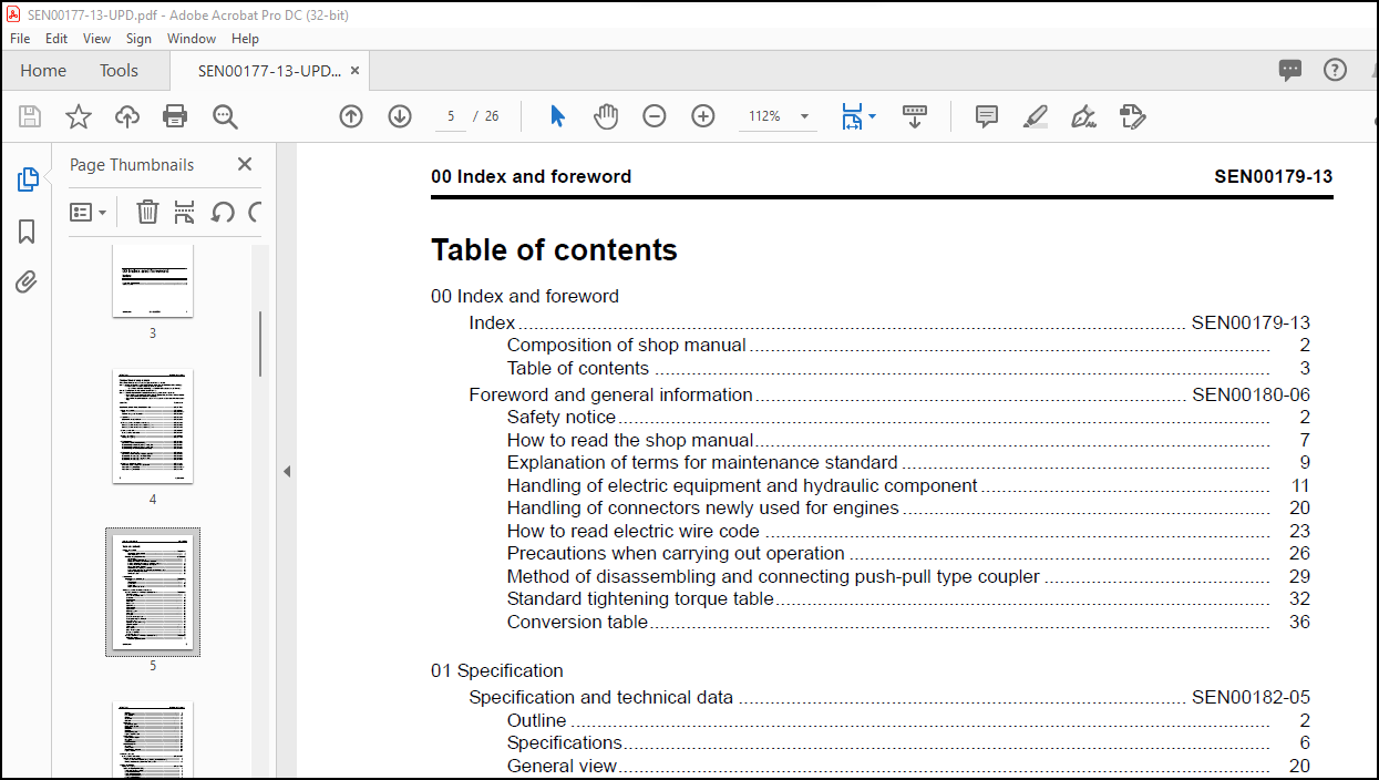
TABLE OF CONTENTS:
Komatsu 125E-5 Series Engine Shop Manual SEN00177-13 – PDF DOWNLOAD
00 Index and foreword
Index ………………………………………………………………………………………………………………. SEN00179-13
Composition of shop manual ……………………………………………………………………………………… 2
Table of contents ……………………………………………………………………………………………………… 3
Foreword and general information………………………………………………………………………. SEN00180-06
Safety notice……………………………………………………………………………………………………………. 2
How to read the shop manual…………………………………………………………………………………….. 7
Explanation of terms for maintenance standard ……………………………………………………………. 9
Handling of electric equipment and hydraulic component ………………………………………………. 11
Handling of connectors newly used for engines ……………………………………………………………. 20
How to read electric wire code …………………………………………………………………………………… 23
Precautions when carrying out operation …………………………………………………………………….. 26
Method of disassembling and connecting push-pull type coupler ……………………………………. 29
Standard tightening torque table…………………………………………………………………………………. 32
Conversion table………………………………………………………………………………………………………. 36
01 Specification
Specification and technical data …………………………………………………………………………. SEN00182-05
Outline ……………………………………………………………………………………………………………………. 2
Specifications…………………………………………………………………………………………………………… 6
General view……………………………………………………………………………………………………………. 20
Weight table…………………………………………………………………………………………………………….. 45
Engine performance curves……………………………………………………………………………………….. 48
10 Structure, function and maintenance standard
Structure, function and maintenance standard, Part 1……………………………………………. SEN00184-05
General structure ………………………………………………………………………………………………………… 4
Air intake and exhaust unit……………………………………………………………………………………………. 6
Air cleaner ………………………………………………………………………………………………………………….. 10
Turbocharger………………………………………………………………………………………………………………. 12
Aftercooler………………………………………………………………………………………………………………….. 19
EGR system ……………………………………………………………………………………………………………….. 20
Cylinder head ……………………………………………………………………………………………………………… 27
Cylinder block……………………………………………………………………………………………………………… 30
Cylinder liner ………………………………………………………………………………………………………………. 34
Main moving parts……………………………………………………………………………………………………….. 35
Crankshaft………………………………………………………………………………………………………………….. 37
Camshaft……………………………………………………………………………………………………………………. 38
Cam follower and push rod …………………………………………………………………………………………… 39
Piston, piston ring and piston pin …………………………………………………………………………………… 40
Connecting rod……………………………………………………………………………………………………………. 42
Flywheel and flywheel housing ……………………………………………………………………………………… 43
Vibration damper…………………………………………………………………………………………………………. 48
Timing gear ………………………………………………………………………………………………………………… 50
Valve system………………………………………………………………………………………………………………. 58
Valve and valve guide ………………………………………………………………………………………………….. 62
Rocker arm and shaft…………………………………………………………………………………………………… 64
Crosshead and guide …………………………………………………………………………………………………… 65
Structure, function and maintenance standard, Part 2……………………………………………. SEN00185-05
Lubrication system ………………………………………………………………………………………………………. 4
Lubrication system diagram……………………………………………………………………………………….. 4
SEN00179-13 00 Index and foreword
4 125E-5 Series
Oil pump …………………………………………………………………………………………………………………. 8
Main relief valve……………………………………………………………………………………………………….. 9
EGR oil pump ………………………………………………………………………………………………………….. 10
Oil filter……………………………………………………………………………………………………………………. 11
Safety valve …………………………………………………………………………………………………………….. 13
Oil cooler…………………………………………………………………………………………………………………. 14
Fuel system ………………………………………………………………………………………………………………… 16
CRI system diagram …………………………………………………………………………………………………. 16
Outline of CRI system……………………………………………………………………………………………….. 18
Fuel piping ………………………………………………………………………………………………………………. 40
Fuel cooler ………………………………………………………………………………………………………………. 42
Fuel filter …………………………………………………………………………………………………………………. 43
Electric priming pump ……………………………………………………………………………………………….. 45
Engine controller cooler …………………………………………………………………………………………….. 46
Cooling system……………………………………………………………………………………………………………. 48
Cooling system diagram ……………………………………………………………………………………………. 48
Water pump …………………………………………………………………………………………………………….. 50
Thermostat………………………………………………………………………………………………………………. 52
Corrosion resistor …………………………………………………………………………………………………….. 54
Electrical equipment …………………………………………………………………………………………………….. 55
Alternator ………………………………………………………………………………………………………………… 55
Starting motor ………………………………………………………………………………………………………….. 62
Electrical intake air heater …………………………………………………………………………………………. 66
Engine controller………………………………………………………………………………………………………. 67
20 Standard value table
Standard service value table………………………………………………………………………………. SEN00546-07
Standard service value table …………………………………………………………………………………………. 2
Standard service value table for testing, adjusting, and troubleshooting…………………………… 2
Running-in standard and performance test standard …………………………………………………….. 15
30 Testing and adjusting
Testing and adjusting ………………………………………………………………………………………… SEN00547-05
Testing and adjusting (With EGR) ………………………………………………………………………………….. 3
Testing and adjusting tools list ……………………………………………………………………………………. 3
Sketches of special tools …………………………………………………………………………………………… 5
Testing air boost pressure………………………………………………………………………………………….. 6
Testing exhaust temperature ……………………………………………………………………………………… 7
Adjusting valve clearance………………………………………………………………………………………….. 8
Testing compression pressure ……………………………………………………………………………………. 9
Testing blow-by pressure …………………………………………………………………………………………… 11
Testing engine oil pressure ………………………………………………………………………………………… 12
Measuring EGR valve and bypass valve drive pressure ………………………………………………… 13
Handling fuel system parts ………………………………………………………………………………………… 14
Releasing residual pressure in fuel system ………………………………………………………………….. 14
Testing fuel pressure…………………………………………………………………………………………………. 15
Reduced cylinder mode operation………………………………………………………………………………. 16
No-injection cranking ………………………………………………………………………………………………… 16
Testing leakage from pressure limiter and return rate from injector………………………………….. 17
Bleeding air from fuel circuit ………………………………………………………………………………………. 20
Testing fuel system for leakage ………………………………………………………………………………….. 22
Adjusting speed sensor …………………………………………………………………………………………….. 23
Testing and adjusting alternator belt tension ………………………………………………………………… 24
Handling controller voltage circuit……………………………………………………………………………….. 25
Testing and adjusting (EGR-less)…………………………………………………………………………………… 26
Testing and adjusting tools list ……………………………………………………………………………………. 26
00 Index and foreword SEN00179-13
125E-5 Series 5
Sketches of special tools …………………………………………………………………………………………… 28
Testing air boost pressure …………………………………………………………………………………………. 29
Testing exhaust temperature ……………………………………………………………………………………… 30
Adjusting valve clearance………………………………………………………………………………………….. 31
Testing compression pressure……………………………………………………………………………………. 32
Testing blow-by pressure…………………………………………………………………………………………… 34
Testing engine oil pressure………………………………………………………………………………………… 35
Handling fuel system parts ………………………………………………………………………………………… 36
Releasing residual pressure in fuel system ………………………………………………………………….. 36
Testing fuel pressure ………………………………………………………………………………………………… 37
Reduced cylinder mode operation………………………………………………………………………………. 38
No-injection cranking ………………………………………………………………………………………………… 38
Testing leakage from pressure limiter and return rate from injector …………………………………. 39
Bleeding air from fuel circuit ………………………………………………………………………………………. 41
Testing fuel system for leakage ………………………………………………………………………………….. 43
Adjusting speed sensor …………………………………………………………………………………………….. 44
Testing and adjusting alternator belt tension ………………………………………………………………… 45
Handling controller voltage circuit……………………………………………………………………………….. 46
40 Troubleshooting
General information on troubleshooting……………………………………………………………….. SEN00548-03
General information on troubleshooting ………………………………………………………………………….. 2
Points on troubleshooting ………………………………………………………………………………………….. 2
Error code and failure code table ……………………………………………………………………………….. 4
Information in troubleshooting table ……………………………………………………………………………. 8
Troubleshooting of electrical system (E-mode), Part 1 …………………………………………… SEN00550-01
Troubleshooting of electrical system (E-mode), Part 1 ……………………………………………………… 4
E-1 Code [111/CA111] ECM Critical Internal Failure………………………………………………………. 4
E-2 Code [115/CA115] Eng. Ne and Bkup Speed Sensor Error ………………………………………. 6
E-3 Code [122/CA122] Charge Air Press Sensor High Error ………………………………………….. 8
E-4 Code [123/CA123] Charge Air Press Sensor Low Error …………………………………………… 10
E-5 Code [131/CA131] Throttle Sensor High Error ……………………………………………………….. 12
E-6 Code [132/CA132] Throttle Sensor Low Error ………………………………………………………… 16
E-7 Code [135/CA135] Oil press. Sensor High Error …………………………………………………….. 18
E-8 Code [141/CA141] Oil press. Sensor Low Error ……………………………………………………… 20
E-9 Code [144/CA144] Coolant Temp. Sensor High Error ……………………………………………… 22
E-10 Code [145/CA145] Coolant Temp. Sensor Low Error …………………………………………….. 24
E-11 Code [153/CA153] Charge Air Temp. Sensor High Error ………………………………………… 26
E-12 Code [154/CA154] Charge Air Temp. Sensor Low Error ………………………………………… 28
E-13 Code [187/CA187] Sensor Sup. 2 Volt. Low Error …………………………………………………. 29
E-14 Code [221/CA221] Ambient Air Press. Sensor High Error………………………………………. 30
E-15 Code [222/CA222] Ambient Air Press. Sensor Low Error……………………………………….. 32
E-16 Code [227/CA227] Sensor Sup. 2 Volt. High Error ………………………………………………… 34
E-17 Code [234/CA234] Eng. Overspeed ……………………………………………………………………. 36
E-18 Code [238/CA238] Ne Speed Sensor Sup. Volt. Error……………………………………………. 38
E-19 Code [263/CA263] Fuel Temp. Sensor High Error…………………………………………………. 40
E-20 Code [265/CA265] Fuel Temp. Sensor Low Error………………………………………………….. 42
E-21 Code [271/CA271] PCV1 Short Error ………………………………………………………………….. 44
E-22 Code [272/CA272] PCV1 Open Error ………………………………………………………………….. 46
E-23 Code [273/CA273] PCV2 Short Error ………………………………………………………………….. 48
E-24 Code [274/CA274] PCV2 Open Error ………………………………………………………………….. 50
E-25 Code [322/CA322] Injector #1 (L/B #1) System Open/Short Error …………………………… 52
E-26 Code [323/CA323] Injector #5 (L/B #5) System Open/Short Error …………………………… 54
E-27 Code [324/CA324] Injector #3 (L/B #3) System Open/Short Error …………………………… 56
E-28 Code [325/CA325] Injector #6 (L/B #6) System Open/Short Error …………………………… 58
E-29 Code [331/CA331] Injector #2 (L/B #2) System Open/Short Error …………………………… 60
E-30 Code [332/CA332] Injector #4 (L/B #4) System Open/Short Error …………………………… 62
SEN00179-13 00 Index and foreword
6 125E-5 Series
E-31 Code [342/CA342] Calibration Code Incompatibility ………………………………………………. 64
E-32 Code [351/CA351] INJ. Drive Circuit Error……………………………………………………………. 66
E-33 Code [352/CA352] Sensor Sup. 1 Volt. Low Error …………………………………………………. 68
E-34 Code [386/CA386] Sensor Sup. 1 Volt. High Error ………………………………………………… 70
E-35 Code [431/CA431] Idle Validation SW Low error …………………………………………………… 72
E-36 Code [432/CA432] Idle Validation Process error……………………………………………………. 74
E-37 Code [441/CA441] Battery voltage low error…………………………………………………………. 74
E-38 Code [442/CA442] Battery voltage high error ……………………………………………………….. 75
Troubleshooting of electrical system (E-mode), Part 2 …………………………………………… SEN00551-01
Troubleshooting of electrical system (E-mode), Part 2………………………………………………………. 3
E-39 Code [449/CA449] Rail Press. Very High Error……………………………………………………… 3
E-40 Code [451/CA451] Rail Press. Sensor High Error …………………………………………………. 4
E-41 Code [452/CA452] Rail Press. Sensor Low Error ………………………………………………….. 6
E-42 Code [553/CA553] Rail Press. High Error…………………………………………………………….. 6
E-43 Code [554/CA554] Rail Press Sensor In Range Error ……………………………………………. 7
E-44 Code [559/CA559] Rail Press. Low Error……………………………………………………………… 8
E-45 Code [689/CA689] Eng. Ne Speed Sensor Error …………………………………………………… 12
E-46 Code [731/CA731] Eng. Bkup Speed Sensor Phase Error ……………………………………… 14
E-47 Code [757/CA757] All Persistent Data Lost Error ………………………………………………….. 15
E-48 Code [778/CA778] Eng. Bkup Speed Sensor Error ……………………………………………….. 16
E-49 Code [1228/CA1228] EGR Valve Servo Error 1…………………………………………………….. 18
E-50 Code [1625/CA1625] EGR Valve Servo Error 2…………………………………………………….. 19
E-51 Code [1626/CA1626] Bypass Valve Solenoid Current High Error…………………………….. 20
E-52 Code [1627/CA1627] Bypass Valve Solenoid Current Low Error……………………………… 22
E-53 Code [1628/CA1628] Bypass Valve Servo Error 1…………………………………………………. 23
E-54 Code [1629/CA1629] Bypass Valve Servo Error 2…………………………………………………. 24
E-55 Code [1631/CA1631] BP valve Lift Position Sensor High Error ……………………………….. 26
E-56 Code [1632/CA1632] BP valve Lift Position Sensor Low Error………………………………… 28
E-57 Code [1633/CA1633] KOMNET Datalink Timeout Error …………………………………………. 28
E-58 Code [1642/CA1642] EGR Inlet Press Sensor Low Error……………………………………….. 29
E-59 Code [1653/CA1653] EGR Inlet Press Sensor High Error ………………………………………. 30
E-60 Code [2185/CA2185] Throttle Sens. Sup. Volt. High Error ……………………………………… 32
E-61 Code [2186/CA2186] Throttle Sens. Sup. Volt. Low Error ………………………………………. 36
E-62 Code [2249/CA2249] Rail Press. Very Low Error ………………………………………………….. 37
E-63 Code [2271/CA2271] EGR Valve Lift Position Sensor High Error…………………………….. 38
E-64 Code [2272/CA2272] EGR Valve Lift Position Sensor Low Error……………………………… 40
E-65 Code [2351/CA2351] EGR Valve Solenoid Current High Error………………………………… 42
E-66 Code [2352/CA2352] EGR Valve Solenoid Current Low Error ………………………………… 44
E-67 Code [2555/CA2555] Grid Heater Relay Volt. Low Error ………………………………………… 45
E-68 Code [2556/CA2556] Grid Heater Relay Volt. High Error ……………………………………….. 46
E-69 Code [(143)/B@BAZG] Eng. Oil press. Torque Derate…………………………………………… 48
E-70 Code [(146)/B@BCNS] Eng. Overheat ………………………………………………………………… 48
E-71 Code [(415)/B@BAZG] Eng. Oil press. Low Speed Derate …………………………………….. 49
Troubleshooting of mechanical system (S-mode)………………………………………………….. SEN00549-02
Troubleshooting of mechanical system (S-mode) …………………………………………………………….. 4
Method of using troubleshooting charts……………………………………………………………………….. 4
S-1 Starting performance is poor ………………………………………………………………………………… 8
S-2 Engine does not start ………………………………………………………………………………………….. 10
S-3 Engine does not pick up smoothly ………………………………………………………………………… 14
S-4 Engine stops during operations…………………………………………………………………………….. 15
S-5 Engine does not rotate smoothly…………………………………………………………………………… 16
S-6 Engine lacks output (or lacks power) …………………………………………………………………….. 17
S-7 Exhaust smoke is black (incomplete combustion) …………………………………………………… 18
S-8 Oil consumption is excessive (or exhaust smoke is blue)…………………………………………. 20
S-9 Oil becomes contaminated quickly………………………………………………………………………… 21
S-10 Fuel consumption is excessive …………………………………………………………………………… 22
S-11 Oil is in coolant (or coolant spurts back or coolant level goes down) ………………………… 23
00 Index and foreword SEN00179-13
125E-5 Series 7
S-12 Oil pressure drops…………………………………………………………………………………………….. 24
S-13 Oil level rises (Entry of coolant or fuel) ………………………………………………………………… 25
S-14 Coolant temperature becomes too high (overheating)……………………………………………. 27
S-15 Abnormal noise is made ……………………………………………………………………………………. 28
S-16 Vibration is excessive ……………………………………………………………………………………….. 29
50 Disassembly and assembly
General information on disassembly and assembly ………………………………………………. SEN00697-03
General information on disassembly and assembly………………………………………………………….. 2
How to read this manual……………………………………………………………………………………………. 2
Coating materials list ………………………………………………………………………………………………… 4
Special tools list ……………………………………………………………………………………………………….. 7
Disassembly and assembly, Part 1 (With EGR)…………………………………………………….. SEN00698-02
Disassembly and assembly, Part 1 (With EGR)……………………………………………………………….. 2
General disassembly of engine ………………………………………………………………………………….. 2
General assembly of engine………………………………………………………………………………………. 17
Disassembly and assembly, Part 2 (EGR-less) …………………………………………………….. SEN00699-03
Disassembly and assembly, Part 2 (EGR-less)………………………………………………………………… 2
General disassembly of engine ………………………………………………………………………………….. 2
General assembly of engine………………………………………………………………………………………. 16
Disassembly and assembly, Part 3……………………………………………………………………… SEN00700-00
Disassembly and assembly, Part 3 ………………………………………………………………………………… 2
Removal and installation of fuel supply pump unit ………………………………………………………… 2
Replacement of oil seal of engine mounted on machine………………………………………………… 4
90 Repair and replacement of parts
Information related to repair and replacement………………………………………………………. SEN05202-00
Flowchart ………………………………………………………………………………………………………………… 2
Special tool table ……………………………………………………………………………………………………… 4
Special tool sketch……………………………………………………………………………………………………. 6
Parts related to cylinder head …………………………………………………………………………….. SEN05203-01
Part names related to cylinder head……………………………………………………………………………. 2
Testing and inspection of cylinder head……………………………………………………………………….. 3
Pressure test of cylinder head ……………………………………………………………………………………. 5
Replacement of valve guide ………………………………………………………………………………………. 5
Replacement of valve seat insert ……………………………………………………………………………….. 6
Replacement of crosshead guide ……………………………………………………………………………….. 13
Repair of valve by grinding ………………………………………………………………………………………… 14
Parts related to cylinder block…………………………………………………………………………….. SEN05204-00
Part names related to cylinder block …………………………………………………………………………… 2
Testing and inspection of cylinder block ………………………………………………………………………. 3
Part names related to crankshaft………………………………………………………………………………… 6
Testing and inspection of crankshaft …………………………………………………………………………… 7
Part names related to connecting rod………………………………………………………………………….. 8
Testing and inspection of connecting rod …………………………………………………………………….. 9
Replacement of flywheel ring gear ……………………………………………………………………………… 11
Replacement of camshaft gear…………………………………………………………………………………… 11
Replacement of main bearing metal cap ……………………………………………………………………… 12
Replacement of connecting rod small end bushing……………………………………………………….. 14
Replacement of cam bushing …………………………………………………………………………………….. 15
Replacement of engine rear seal………………………………………………………………………………… 17
Replacement of wear sleeve (when sleeve is installed) …………………………………………………. 21
Repair of crankshaft by grinding …………………………………………………………………………………. 22
More products