$35
Komatsu 125E-6 Series Engine Shop Manual SEN05624-04 – PDF DOWNLOAD
Komatsu 125E-6 Series Engine Shop Manual SEN05624-04 – PDF DOWNLOAD
FILE DETAILS:
Komatsu 125E-6 Series Engine Shop Manual SEN05624-04 – PDF DOWNLOAD
Language : English
Pages : 340
Downloadable : Yes
File Type : PDF
Size: 18.7 MB
IMAGES PREVIEW OF THE MANUAL:
DESCRIPTION:
Komatsu 125E-6 Series Engine Shop Manual SEN05624-04 – PDF DOWNLOAD
The Komatsu 125E-6 Series Engine Shop Manual, also known as the SEN05624-04 manual, is a comprehensive guide for servicing, maintaining, and repairing the Komatsu 125E-6 series engine. This engine is commonly used in a range of heavy equipment, including excavators, bulldozers, and loaders. The manual is published by Komatsu, a leading manufacturer of heavy equipment and construction machinery, and is designed for use by qualified mechanics and technicians.
The manual is divided into several sections, each of which provides specific information on different aspects of the engine. The sections include:
- General information: This section provides an overview of the engine, including its specifications, features, and operating principles. It also includes information on safety precautions, tools, and equipment needed for maintenance and repair.
- Inspection and adjustment: This section provides detailed instructions on how to inspect and adjust various components of the engine, including the cylinder head, valves, fuel system, and cooling system.
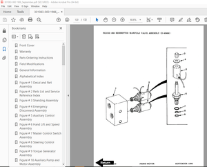
- Engine disassembly and assembly: This section provides step-by-step instructions on how to disassemble and assemble the engine. It includes detailed diagrams and illustrations to help users understand each step of the process.
- Troubleshooting: This section provides a comprehensive list of potential problems that may arise with the engine, along with diagnostic procedures to help identify and fix these issues.
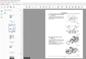
- Maintenance: This section provides information on the regular maintenance tasks that should be performed on the engine, including oil changes, filter replacements, and other routine tasks.
- Reassembly and testing: This section provides detailed instructions on how to reassemble the engine after repairs have been made. It also includes information on how to test the engine to ensure that it is functioning properly.
- Service data: This section provides detailed technical data on the engine, including torque specifications, compression pressures, and other important information.
The manual is written in clear, concise language and is filled with detailed diagrams and illustrations to help users understand each step of the process. It is an essential tool for anyone who works with Komatsu engines and can help to ensure that the engine is maintained and repaired to the highest standards.
However, it should be noted that the manual is designed for use by qualified mechanics and technicians and should not be used by individuals without the appropriate training and experience. The manual is also specifically for the 125E-6 series engine and should not be used as a reference for other engines in the Komatsu lineup.
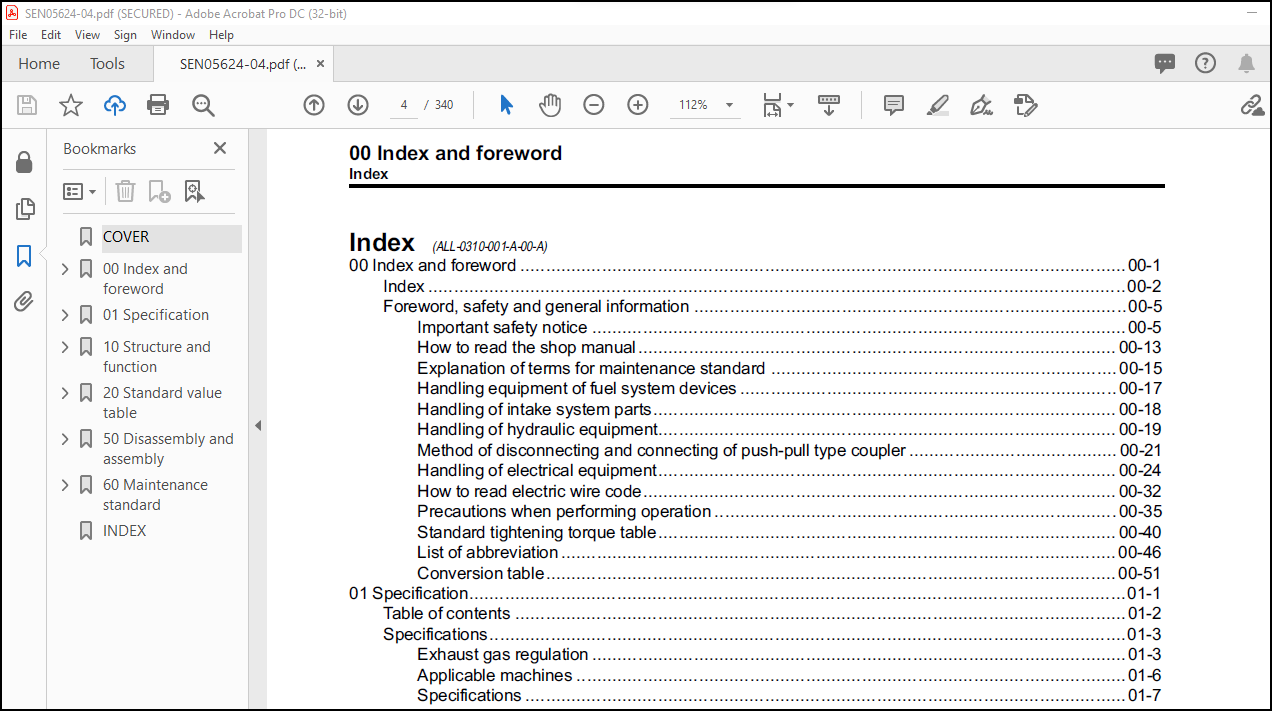
TABLE OF CONTENTS:
Komatsu 125E-6 Series Engine Shop Manual SEN05624-04 – PDF DOWNLOAD
COVER………………………………………………………………….. 1
00 Index and foreword …………………………………………………… 3
Index ……………………………………………………………… 4
Foreword, safety and general information ………………………………. 7
Important safety notice ………………………………………….. 7
How to read the shop manual ………………………………………. 15
Explanation of terms for maintenance standard ………………………. 17
Handling equipment of fuel system devices ………………………….. 19
Handling of intake system parts …………………………………… 20
Handling of hydraulic equipment …………………………………… 21
Method of disconnecting and connecting of push-pull type coupler ……… 23
Handling of electrical equipment ………………………………….. 26
How to read electric wire code ……………………………………. 34
Precautions when performing operation ……………………………… 37
Standard tightening torque table ………………………………….. 42
List of abbreviation …………………………………………….. 48
Conversion table ………………………………………………… 53
01 Specification ……………………………………………………….. 59
Table of contents …………………………………………………… 60
Specifications ……………………………………………………… 61
Exhaust gas regulation …………………………………………… 61
Applicable machines ……………………………………………… 64
Specifications ………………………………………………….. 65
General view ……………………………………………………. 68
Weight table ……………………………………………………. 82
Engine performance curve …………………………………………. 83
10 Structure and function ……………………………………………….. 87
Table of contents …………………………………………………… 88
Components layout …………………………………………………… 89
Components layout drawing ………………………………………… 89
Intake and exhaust system parts ………………………………………. 92
Intake and exhaust system layout drawing …………………………… 92
Intake and exhaust system circuit diagram ………………………….. 93
Air cleaner …………………………………………………….. 95
KVGT …………………………………………………………… 96
Aftercooler ……………………………………………………..102
EGR system piping drawing …………………………………………103
EGR system circuit diagram ………………………………………..105
EGR valve ……………………………………………………….106
EGR cooler ………………………………………………………108
Mixing connector …………………………………………………110
KCCV layout drawing ………………………………………………111
KCCV ventilator ………………………………………………….113
KDPF ……………………………………………………………117
Engine main body parts ……………………………………………….121
Cylinder head ……………………………………………………121
Cylinder block …………………………………………………..123
Main moving parts ………………………………………………..125
Vibration damper …………………………………………………128
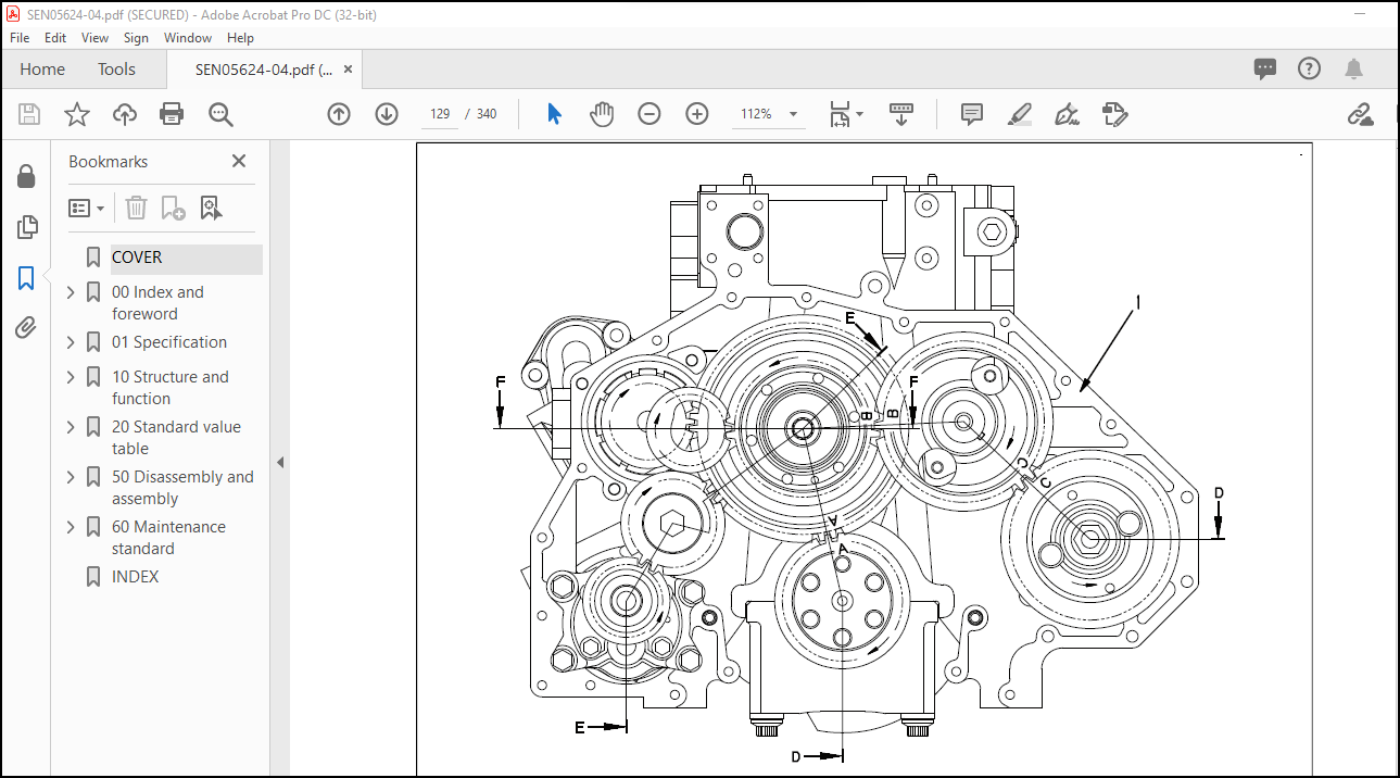
Timing gear ……………………………………………………..129
Front cover ……………………………………………………..131
Valve system …………………………………………………….132
Flywheel and flywheel housing ……………………………………..135
Lubrication system …………………………………………………..136
Lubrication system parts layout drawing …………………………….136
Lubrication system diagram ………………………………………..137
Oil pump ………………………………………………………..138
Boost oil pump …………………………………………………..139
Oil filter ………………………………………………………140
Oil cooler ………………………………………………………141
Oil cooler thermo-valve …………………………………………..142
Oil pan …………………………………………………………143
Fuel system …………………………………………………………144
Fuel system parts layout drawing …………………………………..144
Fuel system circuit diagram ……………………………………….146
Outline of CRI system …………………………………………….149
Fuel dozing ……………………………………………………..162
Fuel cooler ……………………………………………………..165
Pre-filter ………………………………………………………166
Main filter ……………………………………………………..167
Cooling system ………………………………………………………168
Cooling system parts layout drawing ………………………………..168
Cooling system circuit diagram …………………………………….169
Water pump ………………………………………………………170
Thermostat ………………………………………………………171
Electrical equipment …………………………………………………173
Alternator ………………………………………………………173
Alternator mounting ………………………………………………177
Starting motor …………………………………………………..178
Fuel feed pump …………………………………………………..182
Fuel feed pump switch …………………………………………….183
Engine wiring harness …………………………………………….184
Engine controller ………………………………………………..186
Sensor ………………………………………………………….192
20 Standard value table ………………………………………………….205
Table of contents ……………………………………………………206
Standard service value table ………………………………………….207
Standard value table for engine ……………………………………207
Running-in standard and performance test standard ……………………213
50 Disassembly and assembly ………………………………………………217
Table of contents ……………………………………………………218
Related information on disassembly and assembly …………………………219
How to read this manual …………………………………………..219
Coating materials list ……………………………………………221
Special tool list ………………………………………………..225
Sketch of special tool ……………………………………………227
Disassembly and assembly ……………………………………………..230
General disassembly of engine ……………………………………..230
General assembly of engine ………………………………………..251
Removal and installation procedure of supply pump as single component ….296
Engine front oil seal replacement procedure …………………………301
Engine rear oil seal replacement procedure ………………………….304
60 Maintenance standard ………………………………………………….309
Table of contents ……………………………………………………310
Intake and exhaust system parts ……………………………………….311
KVGT ……………………………………………………………311
Engine main body parts ……………………………………………….312
Cylinder head ……………………………………………………312
Cylinder block …………………………………………………..313
Cylinder liner …………………………………………………..315
Crankshaft ………………………………………………………316
Cam follower and push rod …………………………………………317
Piston ………………………………………………………….319
Connecting rod …………………………………………………..321
Vibration damper …………………………………………………323
Timing gear ……………………………………………………..324
Camshaft ………………………………………………………..325
Valve and valve guide …………………………………………….326
Rocker arm ………………………………………………………328
Crosshead and guide ………………………………………………329
Flywheel ………………………………………………………..330
Lubrication system …………………………………………………..332
Main relief valve ………………………………………………..332
Safety valve …………………………………………………….333
Cooling system ………………………………………………………334
Oil cooler ………………………………………………………334
Water pump ………………………………………………………335
Thermostat ………………………………………………………336
INDEX…………………………………………………………………..337
More products