$43
Komatsu 12V140E -7 Series Engine Shop Manual SEN06656-05 – PDF DOWNLOAD
Komatsu 12V140E -7 Series Engine Shop Manual SEN06656-05 – PDF DOWNLOAD
FILE DETAILS:
Komatsu 12V140E -7 Series Engine Shop Manual SEN06656-05 – PDF DOWNLOAD
Language : English
Pages : 1070
Downloadable : Yes
File Type : PDF
Size: 55.9 MB
DESCRIPTION:
Komatsu 12V140E -7 Series Engine Shop Manual SEN06656-05 – PDF DOWNLOAD
FOREWORD, SAFETY, BASIC INFORMATION
HOW TO READ THE ENGINE SHOP MANUAL
• Some of the attachments and options described in this shop manual may not be available in some areas. If
they are required, consult your Komatsu distributor.
• The materials and specifications are subject to change without notice.
• Shop manuals are available for “machine part” and “engine part”. For the engine unit, see the shop manual
for the machine which has the same engine model.
• Actual machine may differ from the images which are contained in this manual. A typical model is shown in
the illustrations of this shop manual.
Composition of the shop manual
This shop manual contains technical information necessary to perform services in workshops. It is divided into
the following chapters for the ease of use.
00 INDEX AND FOREWORD
This section describes the index, foreword, safety, and basic information.
01 SPECIFICATIONS
This section describes the specifications of the machine.
10 STRUCTURE AND FUNCTION
This section describes the structure and operation of each component with respect to each system. “STRUCTURE
AND FUNCTION” is helpful in not only understanding the structure of each component but performing
troubleshooting.
20 STANDARD VALUE TABLE
This section describes the standard values for new machine and failure criteria for testing and adjusting, and
troubleshooting. Use the standard values table to check the standard values for testing and adjusting, and judge
troubles in troubleshooting.
50 DISASSEMBLY AND ASSEMBLY
This section describes the special tools, work procedures, and safety precautions necessary for removal, installation,
disassembly, and assembly of the components and parts. In addition, tightening torques, quantity, and
weight of the coating materials, lubricants, and coolant necessary to these works are shown.
60 MAINTENANCE STANDARD
This section describes the maintenance standard value of each component. The maintenance standard shows
the criteria and remedies for disassembly and assembly.
General precautions
If the machine is handled incorrectly, it is dangerous. Read and understand what is described in the
operation and maintenance manual before operation. Read and understand what is described in this
manual before operation.
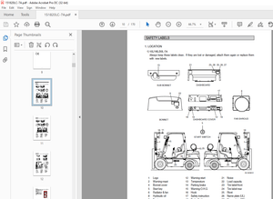
• Read and understand the meaning of all the safety labels stuck to the machine before performing any
greasing or repairs. For the locations of the safety labels and detailed explanation of precautions, see Operation
and Maintenance Manual.
• Tools and removed parts in the workshop should be well organized. Always keep the tools and parts in their
correct places. Always keep the work area clean and make sure that there is no dust, dirt, oil, or water on
the floor. Smoke only in the designated areas. Never smoke while working.
• Keep all tools in good condition, learn the correct way to use them, and use the proper ones. Check the
tools, machine, forklift truck, service car, etc. thoroughly before starting the work.
• Always wear safety shoes and helmet when performing
any operation. Do not wear loose clothes, or clothes with
buttons missing.
• Always wear the protective eyeglasses when hitting parts
with a hammer.
• Always wear the protective eyeglasses when grinding
parts with a grinder, etc.
• When performing any operation with multiple workers, always
agree on the operating procedure before starting. Be
clear in verbal communication, and observe hand signals.
Hang “UNDER REPAIR” warning tag in the operator’s
compartment Before starting work.
• Work and operation which require license or qualification
should be performed by qualified workers.
• Welding repairs should be performed by trained and experienced welders. When performing welding work,
always wear welding gloves, apron, welding goggles, cap and other clothes suited for welding work.
• Warm up before starting the work with exercise which increases alertness and the range of motion in order
to prevent injury.
• Avoid prolonged work, and take a rest at times to keep up a good condition. Take a rest at designated safe
area.
Precautions for preparatory work:
• Place the machine on a firm and level ground, and apply the parking brake and chock the wheels or tracks
to prevent the machine from moving before adding oil or making any repairs.
• Lower the work equipment (blade, ripper, bucket, etc.) to the ground before starting work. If this is not possible,
insert the lock pin or use blocks to prevent the work equipment from falling. In addition, be sure to
lock all the control levers and hang “UNDER REPAIR” warning tag on them.
• When performing the disassembling or assembling work, support the machine securely with blocks, jacks,
or stands before starting the work.
• Remove all mud and oil from the steps or other places for going up and down on the machine. Always use the handrails, ladders or steps when for going up and down on the machine. Never jump on or off the machine. When the scaffold is not provided, use steps or stepladder to secure your footing. Do not use handrails, ladders, or steps if they are damaged or deformed. Repair it or replace it immediately.
TABLE OF CONTENTS:
Komatsu 12V140E -7 Series Engine Shop Manual SEN06656-05 – PDF DOWNLOAD
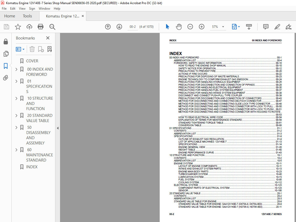
00 INDEX AND FOREWORD 00-1
ABBREVIATION LIST 00-4
FOREWORD, SAFETY, BASIC INFORMATION 00-10
HOW TO READ THE ENGINE SHOP MANUAL 00-10
SAFETY NOTICE FOR OPERATION 00-12
PRECAUTIONS TO PREVENT FIRE 00-20
ACTIONS IF FIRE OCCURS 00-22
PRECAUTIONS FOR DISPOSING OF WASTE MATERIALS 00-23
ENGINE TECHNOLOGY TO CONFORM EXHAUST GAS EMISSION 00-24
PRECAUTIONS FOR HANDLING HYDRAULIC EQUIPMENT 00-25
PRECAUTIONS FOR DISCONNECTION AND CONNECTION OF PIPINGS 00-28
PRECAUTIONS FOR HANDLING ELECTRICAL EQUIPMENT 00-35
PRECAUTIONS FOR HANDLING FUEL SYSTEM EQUIPMENT 00-37
PRECAUTIONS FOR HANDLING INTAKE SYSTEM EQUIPMENT 00-38
DISCONNECT AND CONNECT PUSH-PULL TYPE COUPLER 00-39
PRECAUTIONS FOR DISCONNECTION AND CONNECTION OF CONNECTORS 00-43
METHOD FOR DISCONNECTING AND CONNECTING DEUTSCH CONNECTOR 00-47
METHOD FOR DISCONNECTING AND CONNECTING SLIDE LOCK TYPE CONNECTOR 00-48
METHOD FOR DISCONNECTING AND CONNECTING CONNECTOR WITH LOCK TO PULL 00-50
METHOD FOR DISCONNECTING AND CONNECTING CONNECTOR WITH LOCK TO PUSH 00-51
METHOD FOR DISCONNECTING AND CONNECTING CONNECTOR WITH HOUSING TO ROTATE
00-53
HOW TO READ ELECTRICAL WIRE CODE 00-54
EXPLANATION OF TERMS FOR MAINTENANCE STANDARD 00-58
STANDARD TIGHTENING TORQUE TABLE 00-61
CONVERSION TABLE 00-68
01 SPECIFICATIONS 01-1
CONTENTS 01-2
ABBREVIATION LIST 01-3
SPECIFICATIONS 01-9
OUTLINE OF EXHAUST GAS REGULATION 01-9
LIST OF APPLICABLE MACHINES: 12V140E-7 01-13
SPECIFICATIONS 01-14
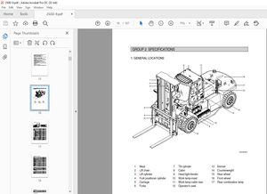
ENGINE GENERAL VIEW 01-20
WEIGHT TABLE 01-40
ENGINE PERFORMANCE CURVE 01-43
10 STRUCTURE AND FUNCTION 10-1
CONTENTS 10-2
ABBREVIATION LIST 10-5
ENGINE SYSTEM 10-11
LAYOUT OF ENGINE COMPONENTS 10-11
INTAKE AND EXHAUST SYSTEM PARTS 10-13
ENGINE MAIN BODY PARTS 10-23
TURBOCHARGER SYSTEM 10-40
LUBRICATION SYSTEM 10-73
FUEL SYSTEM 10-85
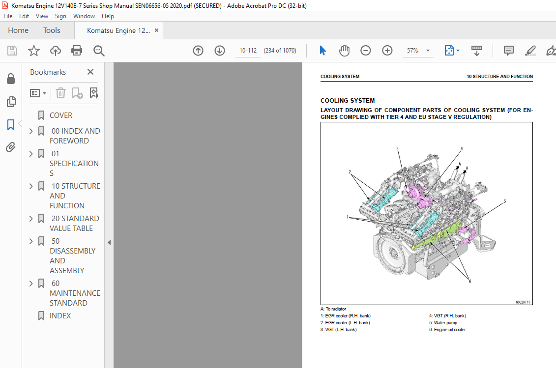
COOLING SYSTEM 10-112
ELECTRICAL SYSTEM 10-123
COMPONENT PARTS OF ELECTRICAL SYSTEM 10-123
SENSOR 10-166
20 STANDARD VALUE TABLE 20-1
CONTENTS 20-2
ABBREVIATION LIST 20-3
STANDARD VALUE TABLE FOR ENGINE 20-9
STANDARD VALUE TABLE FOR ENGINE: SAA12V140E-7 (D475A-8, D475A-8E0) 20-9
STANDARD VALUE TABLE FOR ENGINE: SAA12V140E-7 (HD785-8, HD785-8E0) 20-11
INDEX 00 INDEX AND FOREWORD
00-2 12V140E-7 SERIES
STANDARD VALUE TABLE FOR ENGINE: SAA12V140E-7 (PC2000-11) 20-13
STANDARD VALUE TABLE FOR ENGINE: SAA12V140E-7 (WA800-8, WA800-8E0, WA900-8,
WA900-8E0) 20-15
STANDARD VALUE TABLE FOR ENGINE: SAA12V140E-7 (WA900-8R) 20-17
MACHINE POSTURE AND PROCEDURE FOR MEASURING PERFORMANCE 20-19
RUNNING-IN STANDARD AND PERFORMANCE TEST STANDARD 20-20
RUNNING-IN STANDARD AND PERFORMANCE TEST STANDARD: SAA12V140E-7 (D475A-8,
D475A-8E0) 20-20
RUNNING-IN STANDARD AND PERFORMANCE TEST STANDARD: SAA12V140E-7 (HD785-8,
HD785-8E0) 20-22
RUNNING-IN STANDARD AND PERFORMANCE TEST STANDARD: SAA12V140E-7 (PC2000-11)
20-24
RUNNING-IN STANDARD AND PERFORMANCE TEST STANDARD: SAA12V140E-7 (WA800-8,
WA800-8E0) 20-26
RUNNING-IN STANDARD AND PERFORMANCE TEST STANDARD: SAA12V140E-7 (WA900-8,
WA900-8E0) 20-28
RUNNING-IN STANDARD AND PERFORMANCE TEST STANDARD: SAA12V140E-7 (WA900-8R)
20-30
50 DISASSEMBLY AND ASSEMBLY 50-1
CONTENTS 50-2
ABBREVIATION LIST 50-6
RELATED INFORMATION ON DISASSEMBLY AND ASSEMBLY 50-12
HOW TO READ THIS MANUAL 50-12
COATING MATERIALS LIST 50-14
SPECIAL TOOLS LIST 50-18
SKETCHES OF SPECIAL TOOLS 50-21
ENGINE SYSTEM 50-23
METHOD FOR DISASSEMBLING ENGINE GENERALLY 50-23
METHOD FOR ASSEMBLING ENGINE GENERALLY 50-301
60 MAINTENANCE STANDARD 60-1
CONTENTS 60-2
ABBREVIATION LIST 60-3
ENGINE SYSTEM 60-9
INTAKE AND EXHAUST SYSTEM PARTS 60-9
ENGINE MAIN BODY PARTS 60-12
LUBRICATION SYSTEM 60-38
COOLING SYSTEM 60-44
INDEX 1
IMAGES PREVIEW OF THE MANUAL:
More products