$37
Komatsu 12V170-1 Series Engine Shop Manual SEBM028506 – PDF DOWNLOAD
Komatsu 12V170-1 Series Engine Shop Manual SEBM028506 – PDF DOWNLOAD
FILE DETAILS:
Komatsu 12V170-1 Series Engine Shop Manual SEBM028506 – PDF DOWNLOAD
Language : English
Pages : 321
Downloadable : Yes
File Type : PDF
Size: 16.7 MB
IMAGES PREVIEW OF THE MANUAL:
DESCRIPTION:
Komatsu 12V170-1 Series Engine Shop Manual SEBM028506 – PDF DOWNLOAD
GENERAL PRECAUTIONS:
Mistakes in operation are extremely dangerous.
Read the Operation and Maintenance Manual carefully
BEFORE operating the machine.
1. Before carrying out any greasing or repairs, read
all the precautions given on the decals which are
fixed to the machine.
2. When carrying out any operation, always
wear safety shoes and helmet. Do not wear
loose work clothes, or clothes with buttons
missing.
• Always wear safety glasses when hitting
parts with a hammer.
• Always wear safety glasses when grinding
parts with a grinder, etc.
3. If welding repairs are needed, always have a
trained, experienced welder carry out the work.
When carrying out welding work, always wear
welding gloves, apron, hand shield, cap and
other clothes suited for welding work.
4. When carrying out any operation with two or
more workers, always agree on the operating
procedure before starting. Always inform your
fellow workers before starting any step of the
operation. Before starting work, hang UNDER
REPAIR signs on the controls in the operator’s
compartment.
5. Keep all tools in good condition and learn the
correct way to use them.
6. Decide a place in the repair workshop to keep
tools and removed parts. Always keep the tools
and parts in their correct places. Always keep
the work area clean and make sure that there is
no dirt or oil on the floor. Smoke only in the areas
provided for smoking. Never smoke while working.
PREPARATIONS FOR WORK
7. Before adding oil or making any repairs, park the
machine on hard, level ground, and block the
wheels or tracks to prevent the machine from
moving.
8. Before starting work, lower blade, ripper, bucket
or any other work equipment to the ground. If
this is not possible, insert the safety pin or use
blocks to prevent the work equipment from falling.
In addition, be sure to lock all the control
levers and hang warning signs on them.
9. When disassembling or assembling, support the
machine with blocks, jacks or stands before
starting work.
10.Remove all mud and oil from the steps or other
places used to get on and off the machine.
Always use the handrails, ladders or steps when
getting on or off the machine. Never jump on or
off the machine. If it is impossible to use the
handrails, ladders or steps, use a stand to provide
safe footing.
TABLE OF CONTENTS:
Komatsu 12V170-1 Series Engine Shop Manual SEBM028506 – PDF DOWNLOAD
COVER…………………………………………………………………………….. 1
CONTENTS………………………………………………………………………….. 2
01 GENERAL………………………………………………………………………… 25
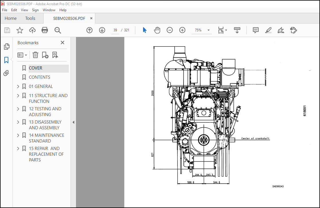
SPECIFICATIONS…………………………………………………………………. 26
ENGINE PERFORMANCE CURVE………………………………………………………… 30
WEIGHT TABLE…………………………………………………………………… 41
11 STRUCTURE AND FUNCTION…………………………………………………………… 44
GENERAL STRUCTURE………………………………………………………………. 45
INTAKE AND EXHAUST SYSTEM……………………………………………………….. 47
AFTER-COOLER……………………………………………………………….. 47
TURBOCHARGER……………………………………………………………….. 48
ENGINE BODY……………………………………………………………………. 51
CYLINDER HEAD………………………………………………………………. 51
VALVE SYSTEM……………………………………………………………….. 53
CYLINDER BLOCK……………………………………………………………… 55
MAIN REVOLVING PART…………………………………………………………. 56
TIMING GEAR………………………………………………………………… 57
FLYWHEEL AND FLYWHEEL HOUSING………………………………………………… 59
LUBRICATION SYSTEM……………………………………………………………… 60
LUBRICATION SYSTEM CHART…………………………………………………….. 60
OIL PUMP ………………………………………………………………….. 62
OIL FILTER…………………………………………………………………. 63
OIL COOLER…………………………………………………………………. 65
OIL COOLER BYPASS VALVE……………………………………………………… 66
PISTON COOLING VALVE………………………………………………………… 66
MECHANICAL PUMP…………………………………………………………….. 67
FUEL SYSTEM……………………………………………………………………. 68
FUEL SYSTEM CHART…………………………………………………………… 68
FUEL INJECTION PUMP…………………………………………………………. 71
FEED PUMP………………………………………………………………….. 72
FUEL INJECTION NOZZLE……………………………………………………….. 73
FUEL INJECTION PUMP DRIVE……………………………………………………. 74
FUEL FILTER………………………………………………………………… 76
INJECTION PUMP RACK CONTROLLER……………………………………………….. 77
AUTOMATIC TIMER…………………………………………………………….. 79
FUEL SOLENOID………………………………………………………………. 80
ENGINE STOP MOTOR…………………………………………………………… 81
COOLING SYSTEM…………………………………………………………………. 86
COOLING SYSTEM CHART………………………………………………………… 86
WATER PUMP…………………………………………………………………. 88
WATER PUMP DRIVE……………………………………………………………. 90
FAN DRIVE AND TENSION PULLEY…………………………………………………. 91
CORROSION RESISTOR………………………………………………………….. 94
THERMOSTAT…………………………………………………………………. 95
ACCESSORY……………………………………………………………………… 96
AIR COMPRESSOR MOUNTING……………………………………………………… 96
AIR COMPRESSOR……………………………………………………………… 97
ALTERNATOR WITH REGULATOR……………………………………………………. 98
STARTING MOTOR……………………………………………………………… 99
AIR STARTING MOTOR…………………………………………………………..100
12 TESTING AND ADJUSTING…………………………………………………………….102
COOLING SYSTEM………………………………………………………………….103
CHECKING AND ADJUSTING FAN BELT TENSION………………………………………..103
CHECKING AND ADJUSTING ALTERNATOR BELT TENSION………………………………….104
ENGINE BODY…………………………………………………………………….105
ADJUSTING VALVE CLEARANCE…………………………………………………….105
MEASURING COMPRESSION PRESSURE………………………………………………..106
MEASURING BLOW-BY……………………………………………………………107
FUEL SYSTEM…………………………………………………………………….109
TESTING AND ADJUSTING OF FUEL INJECTION TIMING………………………………….109
ADJUSTING FUEL INJECTION PUMP RACK LINKAGE……………………………………..111
ADJUSTING ENGINE STOP MOTOR…………………………………………………..112
ADJUSTING ENGINE SPEED SENSOR…………………………………………………113
ADJUSTING FUEL INJECTION PRESSURE (VALVE CRACKING PRESSURE)………………………114
FUEL INJECTION PUMP CALIBRATION DATA…………………………………………..116
PERFORMANCE TEST………………………………………………………………..124
RUN-IN STANDARD……………………………………………………………..124
PERFORMANCE TEST CRITERIA…………………………………………………….126
TESTING AND ADJUSTING DATA……………………………………………………130
TESTING AND ADJUSTING TOOL LIST……………………………………………….134
TROUBLESHOOTING…………………………………………………………………137
POINTS TO REMEMBER WHEN TROUBLESHOOTING………………………………………..138
METHOD OF USING TROUBLESHOOTING CHART………………………………………….139
S-1 STARTING PERFORMANCE IS POOR(STARTING ALWAYS TAKES TIME)……………………..144
S-2 ENGINE DOES NOT START…………………………………………………….145
(1) ENGINE DOES NOT TURN………………………………………………….145
(2) ENGINE TURNS BUT NO EXHAUST GAS COMES OUT (FUEL IS NOT BEING INJECTED)……..146
(3) EXHAUST SMOKE COMES OUT BUT ENGINE DOES NOT START (FUEL IS BEING INJECTED)….147
S-3 ENGINE DOES NOT PICK-UP SMOOTHLY(FOLLOW-UP IS POOR)………………………….148
S-4 ENGINE STOPS DURING OPERATIONS…………………………………………….149
S-5 ENGINE DOES NOT ROTATE SMOOTHLY (HUNTING)…………………………………..150
S-6 ENGINE LACKS OUTPUT (NOT POWER)……………………………………………151
S-7 EXHAUST GAS IS BLACK (INCOMPLETE COMBUSTION)………………………………..152
S-8 OIL CONSUMPTION IS EXCESSIVE (OR EXHAUST SMOKE IS BLUE)………………………153
S-9 OIL BECOMES CONTAMINATED QUICKLY…………………………………………..154
S-10 FUEL CONSUMPTION IS EXCESSIVE…………………………………………….155
S-11 OIL IS COOLING WATER, OR WATER SPURTS BACK, OR WATER LEVEL GOES DOWN………….156
S-12 OIL PRESSURE CAUTION LAMP LIGHTS UP (DROP IN OIL PRESSURE)…………………..157
S-13 OIL LEVEL RISES…………………………………………………………158
S-14 COOLANT TEMPERATURE BECOMES TOO HIGH (OVERHEATING)………………………….159
S-15 ABNORMAL NOISE IS MADE…………………………………………………..160
S-16 VIBRATION IS EXCESSIVE…………………………………………………..161
13 DISASSEMBLY AND ASSEMBLY………………………………………………………….162
GENERAL DISASSEMBLY CONTENTS……………………………………………………..163
DISASSEMBLY…………………………………………………………………….164
ASSEMBLY……………………………………………………………………….192
14 MAINTENANCE STANDARD……………………………………………………………..246
INTAKE AND EXHAUST SYSTEM………………………………………………………..247
TURBOCHARGER………………………………………………………………..247
VALVE AND VALVE GUIDE………………………………………………………..249
VALVES AND VALVE GUIDE……………………………………………………….250
CROSSHEAD AND CROSSHEAD GUIDE…………………………………………………251
ROCKER ARM SHAFT…………………………………………………………….252
PUSH ROD AND CAM FOLLOWER…………………………………………………….253
CYLINDER BLOCK………………………………………………………………255
CYLINDER LINER………………………………………………………………257
CAMSHAFT……………………………………………………………………258
CRANKSHAFT………………………………………………………………….259
POSTON……………………………………………………………………..261
CONNECTING ROD………………………………………………………………262
TIMING GEAR…………………………………………………………………263
FLYWHEEL, FLYWHEEL HOUSING …………………………………………………..264
LUBRICATION SYSTEM………………………………………………………………265
OIL PUMP……………………………………………………………………265
MAIN RELIEF VALVE, POSITION COOLNG VALVE AND OIL COOLER BYPASS VAVLE………………266
COOLING SYSTEM………………………………………………………………….267
WATER PUMP………………………………………………………………….267
15 REPAIR AND REPLACEMENT OF PARTS…………………………………………………..268
TABLE OF SPECIAL TOOLS…………………………………………………………..269
TESTING AND INSPECTING CYLINDER HEAD………………………………………………270
REPAIRING MOUNTING FACE OF CYLINDER HEAD BY GRINDING………………………………..273
REPLACING VALVE SEAT INSERTS……………………………………………………..274
REPLACING NOZZLE HOLDER SLEEVE……………………………………………………280
CYLINDER HEAD PRESSURE TEST METHOD………………………………………………..283
REPLACING VALVE GUIDE……………………………………………………………284
REPLACING CROSS HEAD GUIDE……………………………………………………….285
GRINDING VALVE………………………………………………………………….286
TESTING AND INSPECTING CYLINDER BLOCK……………………………………………..287
GRINDING TOP SURFACE OF CYLINDING BLOCK……………………………………………290
REPLACING MAIN BEARING CAP……………………………………………………….296
REPLACING CAM BUSHING……………………………………………………………299
TESTING CRANKSHAFT………………………………………………………………301
CORRECTING SURFACE ROUGHNESS OF CRANKSHAFT JOURNAL PORTION…………………………..303
GRINDING CRANKSHAFT……………………………………………………………..308
TESTING AND INSPECTING CONNECTING ROD……………………………………………..317
REPLACING CONNECTING ROD SMALL END BUSHING…………………………………………319
REPLACING CAMSHAFT GEAR………………………………………………………….320
REPLACING FLYWHEEL RING GEAR …………………………………………………….321
More products