$36
Komatsu 140E-6 Series Engine Shop Manual SEN05641-04 – PDF DOWNLOAD
Komatsu 140E-6 Series Engine Shop Manual SEN05641-04 – PDF DOWNLOAD
FILE DETAILS:
Komatsu 140E-6 Series Engine Shop Manual SEN05641-04 – PDF DOWNLOAD
Language : English
Pages : 316
Downloadable : Yes
File Type : PDF
Size: 13.8 MB
IMAGES PREVIEW OF THE MANUAL:
DESCRIPTION:
Komatsu 140E-6 Series Engine Shop Manual SEN05641-04 – PDF DOWNLOAD
The Komatsu 6D170-1 Series Diesel Engine Shop Manual SEBE6161A16 is a comprehensive guidebook that provides technical information and detailed instructions on how to operate, maintain, and repair the Komatsu 6D170-1 series diesel engines. This engine series is commonly used in heavy equipment such as excavators, bulldozers, and other heavy machinery.
- The manual is divided into several sections, each providing detailed information on specific topics. These sections include specifications, structure and function, testing and adjusting, disassembly and assembly, maintenance, and troubleshooting.
- The specifications section of the manual provides detailed information on the engine’s physical and operational characteristics, including its dimensions, weight, performance, and power output. It also provides information on the engine’s cooling system, fuel system, and lubrication system.
- The structure and function section of the manual provides an overview of the engine’s internal components and their functions. This section includes detailed diagrams and descriptions of the engine’s various components, such as the cylinder block, cylinder head, crankshaft, pistons, and valves.
- The testing and adjusting section of the manual provides instructions on how to test and adjust the engine’s various components to ensure they are functioning correctly. This section includes detailed procedures for testing and adjusting the engine’s fuel injection system, valve clearances, and oil pressure.
- The disassembly and assembly section of the manual provides step-by-step instructions on how to disassemble and reassemble the engine’s various components. This section includes detailed diagrams and photographs to guide the user through the process.
- The maintenance section of the manual provides information on routine maintenance tasks that should be performed to keep the engine in good working condition. This section includes instructions on how to perform tasks such as changing the engine oil and replacing the air filter.
- The troubleshooting section of the manual provides guidance on how to diagnose and resolve common issues that may arise with the engine. This section includes a list of common symptoms and their likely causes, as well as step-by-step instructions for troubleshooting and resolving each issue.
- Overall, the Komatsu 6D170-1 Series Diesel Engine Shop Manual SEBE6161A16 is an essential resource for anyone who works with or operates machinery that utilizes this engine series. It provides a wealth of technical information, detailed instructions, and troubleshooting guidance that can help keep the engine running smoothly and extend its lifespan.
TABLE OF CONTENTS:
Komatsu 140E-6 Series Engine Shop Manual SEN05641-04 – PDF DOWNLOAD
Cover……………………………………………………………… 1
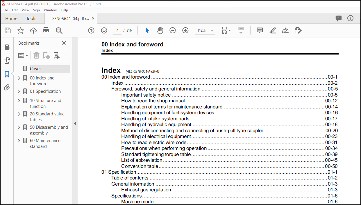
00 Index and foreword ………………………………………………. 3
Index …………………………………………………………. 4
Foreword, safety and general information ………………………….. 7
Important safety notice ……………………………………… 7
How to read the shop manual ………………………………….. 14
Explanation of terms for maintenance standard ………………….. 16
Handling equipment of fuel system devices ……………………… 18
Handling of intake system parts ………………………………. 19
Handling of hydraulic equipment ………………………………. 20
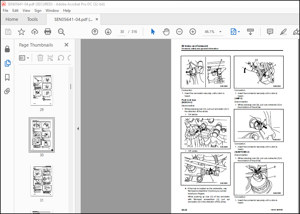
Method of disconnecting and connecting of push-pull type coupler …. 22
Handling of electrical equipment ……………………………… 25
How to read electric wire code ……………………………….. 33
Precautions when performing operation …………………………. 36
Standard tightening torque table ……………………………… 41
List of abbreviation ………………………………………… 47
Conversion table ……………………………………………. 52
01 Specification …………………………………………………… 57
Table of contents ………………………………………………. 58
General information …………………………………………….. 59
Exhaust gas regulation ………………………………………. 59
Specifications …………………………………………………. 62
Machine model ………………………………………………. 62
Specifications ……………………………………………… 63
General view ……………………………………………….. 66
Weight table ……………………………………………….. 79
Engine performance curve …………………………………….. 80
10 Structure and function …………………………………………… 85
Table of contents ………………………………………………. 86
Components layout ………………………………………………. 88
Components layout drawing ……………………………………. 88
Intake and exhaust system parts ………………………………….. 91
Intake and exhaust system layout drawing ………………………. 91
Intake and exhaust system circuit diagram ……………………… 93
Air cleaner ………………………………………………… 95
KVGT ………………………………………………………. 96
Aftercooler …………………………………………………102
EGR system piping drawing …………………………………….103
EGR system circuit diagram ……………………………………105
EGR valve …………………………………………………..106
EGR cooler ………………………………………………….108
Mixing connector …………………………………………….110
KCCV layout drawing ………………………………………….111
KCCV ventilator ……………………………………………..113
KDPF ……………………………………………………….117
Engine main body parts …………………………………………..121
Cylinder head ……………………………………………….121
Cylinder block ………………………………………………123
Main moving parts ……………………………………………125
Timing gear …………………………………………………128
Front cover …………………………………………………129
Valve system ………………………………………………..130
Flywheel and flywheel housing …………………………………132
Lubrication system ………………………………………………133
Lubrication system parts layout drawing ………………………..133
Lubrication system diagram ……………………………………134
Oil pump ……………………………………………………135
Boost oil pump ………………………………………………137
Oil filter ………………………………………………….139
Oil cooler ………………………………………………….140
Oil cooler thermo-valve ………………………………………142
Oil pan …………………………………………………….143
Fuel system …………………………………………………….144
Fuel system parts layout drawing ………………………………144
Fuel system circuit diagram …………………………………..146
Outline of CRI system ……………………………………………149
Fuel system …………………………………………………149
Various controls …………………………………………….150
Structure and operation of CRI system ………………………….152
Structure and operation of component parts ……………………..153
Fuel dozing …………………………………………………….163
Dozing piping drawing ………………………………………..163
Pre-filter ………………………………………………….166
Main filter …………………………………………………167
Cooling system ………………………………………………….168
Cooling system parts layout drawing ……………………………168
Cooling system circuit diagram ………………………………..169
Water pump ………………………………………………….170
Thermostat ………………………………………………….172
Electrical equipment …………………………………………….174
Alternator ………………………………………………….174
Alternator mounting ………………………………………….177
Starting motor ………………………………………………178
Fuel feed pump ………………………………………………180
Fuel feed pump switch ………………………………………..181
Engine wiring harness ………………………………………..182
Engine controller ……………………………………………184
Sensor ……………………………………………………..190
20 Standard value tables …………………………………………….203
Table of contents ……………………………………………….204
Standard service value table ……………………………………..205
Standard value table for engine ……………………………….205
Running-in standard and performance test standard ……………….211
50 Disassembly and assembly ………………………………………….215
Table of contents ……………………………………………….216
Related information on disassembly and assembly …………………….217
How to read this manual ………………………………………217
Coating materials list ……………………………………….219
Special tools list …………………………………………..223
Sketches of special tools …………………………………….225
Disassembly and assembly …………………………………………228
General disassembly of engine …………………………………228
General assembly of engine ……………………………………243
Removal and installation of supply pump ………………………..275
Procedures for replacing engine front oil seal ………………….279
Procedures for replacing engine rear oil seal …………………..282
60 Maintenance standard ……………………………………………..287
Table of contents ……………………………………………….288
Intake and exhaust system parts …………………………………..289
KVGT ……………………………………………………….289
Engine main body parts …………………………………………..290
Cylinder head ……………………………………………….290
Cylinder block ………………………………………………291
Cylinder liner ………………………………………………293
Crankshaft ………………………………………………….294
Cam follower and push rod …………………………………….295
Piston ……………………………………………………..296
Connecting rod ………………………………………………298
Timing gear …………………………………………………300
Camshaft ……………………………………………………302
Valve and valve guide ………………………………………..303
Rocker arm ………………………………………………….305
Crosshead and guide ………………………………………….306
Flywheel ……………………………………………………307
Cooling system ………………………………………………….309
Oil cooler ………………………………………………….309
Water pump ………………………………………………….311
More products