Starting from:
$45
Komatsu 210M Dump Truck Operation & Maintenance Manual BFA40DP- EP 24577-24647 A10609- A10624 PDF
Komatsu 210M Dump Truck Operation & Maintenance Manual BFA40DP- EP 24577-24647 A10609- A10624
Description:
Komatsu 210M Dump Truck Operation & Maintenance Manual BFA40DP- EP 24577-24647 A10609- A10624
- This Manual is written for use by the operator and/or the service technician and is designed to help these persons to become fully knowledgeable of the truck and all its systems in order to keep it operating safely and efficiently.
- All operators and maintenance personnel should read and understand the materials in this manual before operating the truck or performing maintenance and/or operational checks on the truck. All safety notices, warnings and cautions should be understood and followed when operating or accomplishing repairs on the truck.
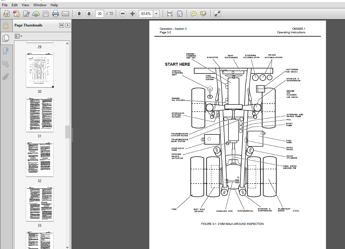
- The first section is an Introduction to the manual and contains a Table of Contents to locate specific areas of interest. Other sections include Safety, Operation, Maintenance, Specifications, and Optional Equipment.
- The illustrations used in this manual are TYPICAL of the component shown and may not be an exact reproduction of what is found on the truck.
- A product identification plate is located on the frame in front of the left side front wheel and designates the Truck Model Number, Product Identification Number (vehicle serial number), and Maximum G.V.W. (Gross Vehicle Weight) rating.
- The HAULPAK® Model designation consists of three numbers and one letter (i.e. 210M). The three numbers represent the basic truck model. The letter “M” designates a Mechanical drive and the letter “E” designates an Electrical wheelmotor drive system.
- The Product Identification Number (vehicle serial number) contains information which will identify the original manufacturing bill of material for this unit. This complete number will be necessary for proper ordering of many service parts and/or warranty consideration.
- The Gross Vehicle Weight (GVW) is what determines the load on the drive train, frame, tires, and other components. The vehicle design and application guidelines are sensitive to the total maximum Gross Vehicle Weight (GVW) and this means the TOTAL WEIGHT: the Empty Vehicle Weight + the fuel & lubricants + the payload.
Table Of Contents:
Komatsu 210M Dump Truck Operation & Maintenance Manual BFA40DP- EP 24577-24647 A10609- A10624
MAIN MENU.......................................................................................... 0
COVER PAGE......................................................................................... 1
INTRODUCTION....................................................................................... 5
	FOREWORD....................................................................................... 5
	ALERTS PAGE - A DESCRIPTION OF THE DANGER, WARNING, AND CAUTION SYMBOLS USED IN THIS MANUAL.... 6
	TABLE OF CONTENTS.............................................................................. 7
	TRUCK MODEL ILLUSTRATION.......................................................................10
	ABOUT THIS MANUAL..............................................................................11
	STANDARD CHARTS AND TABLES.....................................................................13
SAFETY.............................................................................................19
	GENERAL SAFETY RULES...........................................................................19
		SAFETY IS THINKING AHEAD...................................................................19
		SAFE PRACTICES START BEFORE THE OPERATOR GETS TO THE EQUIPMENT.............................19
		AT THE TRUCK - GROUND LEVEL INSPECTION.....................................................19
		PREPARING FOR OPERATION....................................................................19
		TRUCK OPERATION............................................................................20
		ADDITIONAL JOB SITE RULES..................................................................21
		WHEN REPAIRS ARE NECESSARY.................................................................22
	WARNING, CAUTION, AND INSTRUCTION PLATES/DECALS................................................23
OPERATION..........................................................................................29
	OPERATING INSTRUCTIONS.........................................................................29
		PREPARING FOR OPERATION....................................................................29
		AT THE TRUCK - GROUND LEVEL WALK AROUND INSPECTION.........................................29
	ENGINE START-UP SAFETY PRACTICES...............................................................32
	AFTER ENGINE HAS STARTED.......................................................................33
	MACHINE OPERATION SAFETY PRECAUTIONS...........................................................33
	LOADING........................................................................................34
	HAULING........................................................................................34
		RETARDER OPERATION.........................................................................34
	PASSING........................................................................................35
	DUMPING........................................................................................35
	TOWING.........................................................................................36
	SAFE PARKING PROCEDURES........................................................................37
	SHUTDOWN PROCEDURE.............................................................................37
OPERATOR CONTROLS AND EQUIPMENT....................................................................39
	(1)  STEERING COLUMN AND CONTROLS..............................................................39
	(2)  DIMMER SWITCH AND TURN SIGNALS............................................................39
	(3)  TILT LEVER................................................................................39
	(4)  HORN AND TELESCOPING ADJUSTMENT...........................................................39
	(5)  HOIST CONTROL LEVER.......................................................................40
	(6)  RETARDER PEDAL............................................................................40
	(7)  SERVICE BRAKE PEDAL.......................................................................41
	(8)  THROTTLE PEDAL............................................................................41
	(9)  LIGHTER...................................................................................41
	(10) ASH TRAY..................................................................................41
	(11) RANGE SELECTOR............................................................................41
	(12) DO NOT SHIFT LIGHT........................................................................42
	OPERATOR SEAT..................................................................................42
INSTRUMENTS AND CONTROLS...........................................................................43
	INSTRUMENT PANEL (FIGURE 3-5)..................................................................43
		(1)  FOG LIGHTS (OPTIONAL).................................................................43
		(2)  LIGHTS - ALL..........................................................................43
		(3)  LIGHTS - INSTRUMENT PANEL.............................................................43
		(4)  WINDSHIELD WASHER.....................................................................43
		(5)  WINDSHIELD WIPER......................................................................43
		(6)  ENGINE STARTING AID...................................................................43
		(7)  KEYSWITCH.............................................................................43
		(8)  ENGINE SHUT DOWN (NOT USED)...........................................................43
		(9)  WINDSHIELD WIPER FUSE HOLDER..........................................................43
	INSTRUMENT PANEL (FIGURE 3-5)..................................................................44
		(10)  TURN SIGNAL FUSE HOLDER..............................................................45
		(11)  CIRCUIT BREAKER......................................................................45
		(12)  CIRCUIT BREAKER......................................................................45
		(13)  CIRCUIT BREAKER......................................................................45
		(14)  BRAKE LOCK...........................................................................45
		(15)  AND (18)  BRAKE  OFF.................................................................45
		(16)  AND (19)  BRAKE  ON..................................................................45
		(17)  PARKING BRAKE........................................................................45
		(20)  SLIPPERY ROAD SWITCH.................................................................45
		(21)  SWITCH OPEN..........................................................................45
		(22)  SWITCH CLOSED........................................................................45
		(23)  TRANSMISSION TEMPERATURE.............................................................46
		(24)  WATER TEMPERATURE....................................................................46
		(25)  TRANSMISSION OIL PRESSURE............................................................46
		(26)  ENGINE OIL PRESSURE..................................................................46
		(27)  BRAKE OIL TEMPERATURE................................................................46
		(28)  VOLTMETER............................................................................46
		(29)  SPEEDOMETER..........................................................................46
		(30)  LEFT TURN INDICATOR (RED LIGHT)......................................................47
		(31)  HIGH BEAM INDICATOR (BLUE LIGHT).....................................................47
		(32)  RIGHT TURN INDICATOR (RED LIGHT).....................................................47
		(33)  TACHOMETER AND HOURMETER.............................................................47
		RETARDER OPERATION.........................................................................47
		(34)  EMERGENCY STEERING...................................................................48
		(35)  BRAKE LOCK...........................................................................48
		(36)  LOW BRAKE PRESSURE WARNING LIGHT.....................................................48
		(37)  PARKING BRAKE........................................................................48
		(38)  COOLANT TEMPERATURE LIGHT............................................................49
		(39)  COOLANT LEVEL........................................................................49
		(40)  TRANSMISSION MAIN FILTER.............................................................49
		(41)  ENGINE OIL PRESSURE..................................................................49
		(42)  HYDRAULIC OIL FILTER.................................................................49
		(43)  BRAKE OIL TEMPERATURE................................................................49
		(44)  TRANSMISSION COOLER FILTER...........................................................50
		(45)  LOW ACCUMULATOR PRECHARGE WARNING LIGHT..............................................50
		(46)  AUTOMATIC FIRE CONTROL (OPTIONAL)....................................................50
		(47)  LOW FUEL INDICATOR (OPTIONAL)........................................................50
		(48)  RESERVED FOR FUTURE ACCESSORIES......................................................50
		(49)  AIR CLEANER INDICATOR (OPTIONAL).....................................................50
		(50)  LAMP TEST SWITCH.....................................................................50
		(51)  ALARM HORN...........................................................................50
		(52)  EQUAL FAULT LIGHT....................................................................51
		(53)  CHECK TRANS LIGHT....................................................................51
		(54)  ALT. FAULT LIGHT.....................................................................51
	CUMMINS "QUANTUM" ENGINE ELECTRONIC CONTROL SYSTEM.............................................51
		(55)  FAULT CHECK SWITCH...................................................................52
		(56)  CHECK ENGINE LIGHT...................................................................52
		(57)  PROT. ENG. LIGHT.....................................................................52
		(58)  STOP ENG. LIGHT......................................................................52
		(59)  FAULT SCROLL SWITCH..................................................................52
		DETERMINING "FAULT" CODES..................................................................52
		EXITING THE DIAGNOSTICS MODE...............................................................52
	HEATER/AIR CONDITIONER (FIGURE 3-7)............................................................53
		(60)  FAN..................................................................................53
		(61)  TEMPERATURE CONTROL KNOB.............................................................53
		(62)  LOUVERS..............................................................................53
		(63)  HEATER/AIR CONDITIONER SWITCH........................................................53
		(64)  AIR CONDITIONING TEMPERATURE CONTROL.................................................53
		(65)  INSIDE/OUTSIDE AIR CONTROL KNOB......................................................53
MAINTENANCE........................................................................................55
	LUBRICATION AND SERVICE........................................................................55
		LUBRICATION CHART..........................................................................56
		10 HOUR (SHIFT) LUBRICATION AND MAINTENANCE CHECKS.........................................57
		100 HOUR LUBRICATION AND MAINTENANCE CHECKS................................................59
		250 HOUR LUBRICATION AND MAINTENANCE CHECKS................................................61
		1000 HOUR LUBRICATION AND MAINTENANCE CHECKS...............................................63
		5000 HOUR LUBRICATION AND MAINTENANCE CHECKS...............................................65
SPECIFICATIONS.....................................................................................67
	MAJOR COMPONENT DESCRIPTIONS...................................................................67
	SPECIFICATIONS.................................................................................69
Screenshot Of the Manual:

More products