Starting from:
$45
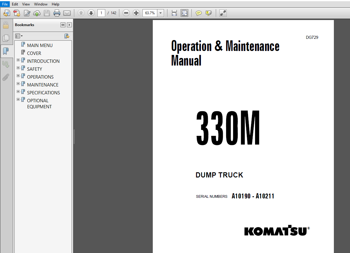
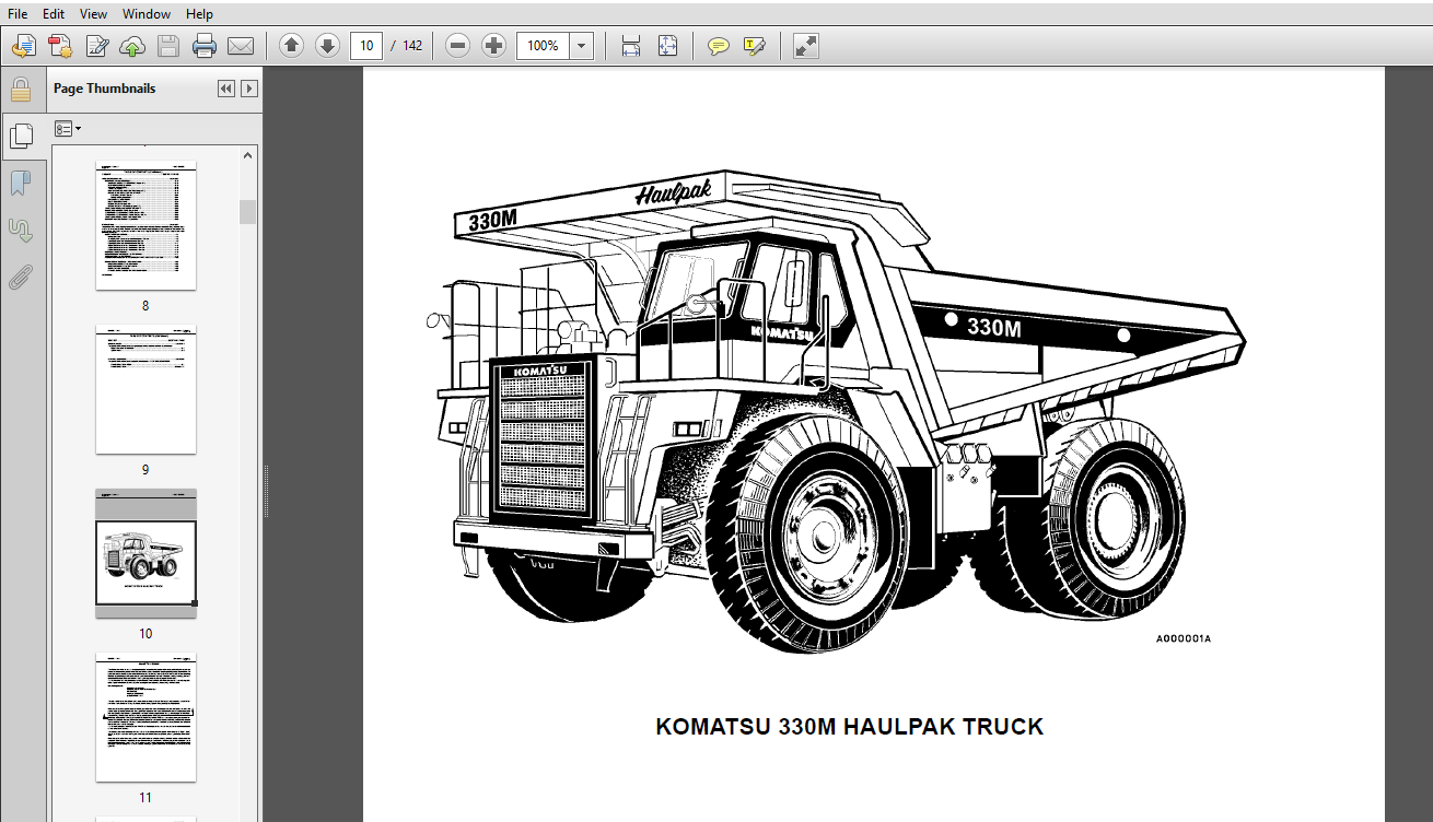
Komatsu 330M Dump Truck Operation & Maintenance Manual SERIAL NUMBERS A10190 -A10211 PDF Download
Komatsu 330M Dump Truck Operation & Maintenance Manual SERIAL NUMBERS A10190-A10211
Description:
Komatsu 330M Dump Truck Operation & Maintenance Manual SERIAL NUMBERS A10190-A10211
- This Manual is written for use by the operator and/or service technician and is designed to help these persons to become fully knowledgeable of the truck and all its systems in order to keep it operating safely and efficiently.
- All operators and maintenance personnel should read and understand the materials in this manual before operating the truck or performing maintenance and/or operational checks on the truck. All safety notices, warnings and cautions should be understood and followed when accomplishing repairs on the truck.
- The first section is an Introduction th the manual and contains a Table of Contents to locate specific areas of interest. Other sections include Safety, Operation, Maintenance, Specifications, and Optional Equipment. The illustrations used in this manual are, at times, typical of the component shown and may not necessarily depict a specific model.
- This manual shows dimensioning of U.S. standard and metric (SI) units throughout and all references to “Right”, “Left”, “Front”, or “Rear” are made with respect to the operator’s normal seated position, unless specifically stated otherwise. Standard torque requirements are shown in torque charts in the general information section and individual torques are provided in the text in bold face type, such as 723 kg.m (100 ft.lbs.) torque.
- All torque specifications have ±10% tolerance unless otherwise specified. A Product Identification plate is normally located on the truck frame upright in front of the left side front wheel and designates the Truck Model Number, Product Identification Number (vehicle serial number), and Maximum G.V.W. (Gross Vehicle Weight) rating.
- The KOMATSU Haulpak Truck Model designation consists of three numbers and one letter (i.e. 330M). The three numbers represent the basic truck model. The letter “M” designates a Mechanical drive and the letter “E” designates an Electrical wheel motor drive system.
- The Product Identification Number (vehicle serial number) contains information which will identify the original manufacturing bill of material for this unit. This complete number will be necessary for proper ordering of many service parts and/or warranty consideration. The Gross Vehicle Weight (GVW) is what determines the load on the drive train, frame, tires, and other components.
- The vehicle design and application guidelines are sensitive to the total maximum Gross Vehicle Weight (GVW) and this means the total weight: the Empty Vehicle Weight + the fuel & lubricants + the payload.
Table Of Contents:
Komatsu 330M Dump Truck Operation & Maintenance Manual SERIAL NUMBERS A10190-A10211\
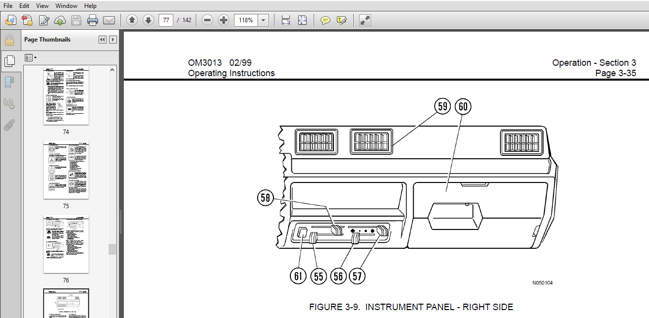
MAIN MENU.........................................................  0
COVER.............................................................  1
INTRODUCTION......................................................  5
	FOREWORD......................................................  5
		ALERTS - a description of DANGER, WARNING, CAUTION........  6
		TABLE OF CONTENTS.........................................  7
		Truck Model Illustration.................................. 10
		About This Manual......................................... 11
		STANDARD TABLES........................................... 13
SAFETY............................................................ 19
	GENERAL SAFETY................................................ 19
	PRECAUTIONS DURING OPERATION.................................. 23
		OPERATING THE MACHINE..................................... 24
		TOWING.................................................... 27
		BATTERY................................................... 28
	PRECAUTIONS FOR MAINTENANCE................................... 29
		BEFORE CARRYING OUT MAINTENANCE........................... 29
		DURING MAINTENANCE........................................ 30
		TIRES..................................................... 33
	WARNINGS AND CAUTIONS......................................... 34
OPERATIONS........................................................ 43
	OPERATING INSTRUCTIONS........................................ 43
		PREPARING FOR OPERATION................................... 43
		SAFETY IS THINKING AHEAD.................................. 43
		At The Truck - Ground Level Walk Around Inspection........ 43
	ENGINE START-UP SAFETY PRACTICES.............................. 47
	AFTER ENGINE HAS STARTED...................................... 49
	MACHINE OPERATION SAFETY PRECAUTIONS.......................... 50
	LOADING....................................................... 50
	HAULING....................................................... 51
	PASSING....................................................... 52
	DUMPING....................................................... 52
	SAFE PARKING PROCEDURES....................................... 54
	SHUTDOWN PROCEDURE............................................ 54
	TOWING........................................................ 54
	BRAKE RELEASE................................................. 55
	RELEASE OF PARKING BRAKE...................................... 55
	RELEASE OF EMERGENCY BRAKE.................................... 56
	OPERATOR CAB AND CONTROLS..................................... 57
		Steering Wheel And Controls............................... 57
		Retarder Control Lever.................................... 58
		Brake Pedal............................................... 58
		Throttle Pedal............................................ 58
		Center Console............................................ 58
		ENGINE ELECTRONIC CONTROL SYSTEM.......................... 61
			Determining "Fault" Codes............................. 63
			EXITING THE DIAGNOSTICS MODE.......................... 63
		Differential Lock Pedal................................... 63
		Hoist Control............................................. 63
		OPERATOR SEAT............................................. 64
		OPERATOR SEAT (KAB Model)................................. 65
	INSTRUMENT PANEL AND INDICATORS............................... 67
	GAUGE AND MONITOR PANEL ...................................... 69
	INDICATORS AND CONTROLS PANEL................................. 68
	INDICATORS AND CONTROL PANEL.................................. 72
	INSTRUMENT PANEL - RIGHT SIDE................................. 77
	Correction Code Display....................................... 78
MAINTENANCE....................................................... 79
	LUBRICATION AND SERVICE....................................... 79
		LUBRICATION CHART......................................... 80
		10 HOUR (DAILY) INSPECTION................................ 81
		250 HOUR SERVICE.......................................... 86
		500 HOUR SERVICE.......................................... 88
		1000 HOUR SERVICE......................................... 89
		EVERY 2000 HOUR SERVICE................................... 90
		EVERY 5000 HOUR SERVICE................................... 91
	HYDRAULIC TANK SERVICE........................................ 92
	HIGH PRESSURE HYDRAULIC FILTERS............................... 94
	TRANSMISSION FILTER........................................... 96
	PERIODIC REPLACEMENT OF COMPONENT PARTS FOR SAFETY DEVICES.... 97
	BRAKE CIRCUIT CHECKOUT AND ADJUSTMENT......................... 98
		CHECKING FRONT BRAKE PAD WEAR............................. 98
		CHECKING REAR BRAKE DISC WEAR............................. 99
		BRAKE SYSTEM BLEEDING.....................................100
		PARKING BRAKE INSPECTION AND ADJUSTMENT...................101
SPECIFICATIONS....................................................103
	MAJOR COMPONENTS..............................................103
	SPECIFICATIONS................................................105
OPTIONAL EQUIPMENT................................................107
	PAYLOAD METER II™ INDEX.......................................107
	PAYLOAD METER II..............................................110
		PAYLOAD METER II ON BOARD WEIGHING SYSTEM (OBWS)..........110
		GENERAL INFORMATION.......................................110
			Haul Cycles...........................................110
		LIGHTS, SWITCHES, and COMPONENTS..........................111
		TIPS FOR OPERATION........................................112
		EXTERNAL DISPLAY LIGHTS...................................112
		THEORY OF OPERATION.......................................113
			Basic Description.....................................113
			Inclinometer..........................................113
			Linkage Factor........................................113
			Gain Factor...........................................114
			Brake Lock............................................114
			Sources of Error......................................114
			Typical Data From Service Check Mode..................114
			Example Calculation of Payload........................115
			Viewing Payload Calculation Inputs....................115
			Checking the Gain.....................................116
			Adjusting the Gain....................................116
		TYPES OF DATA STORED......................................117
			Cycle Data............................................117
			Engine ON/OFF Data....................................118
			Fault Codes and Warning Data..........................118
			Engine Operation......................................119
			Total Payload and Total Number of Cycles..............119
			Other Data............................................119
		OPERATOR FUNCTIONS........................................120
			Using the Operator Load Counter.......................120
			Viewing the Operator Load Counter.....................120
			Clearing the Operator Load Counter....................120
			Dimming the Lights on the Display.....................120
		INITIAL SETUP OF PAYLOAD METER............................121
			Switch Settings.......................................121
			Checking the Operator Check Mode......................122
			Checking the Service Check Mode.......................122
			Checking the Gt setting:..............................123
			Checking the Inclinometer Settings....................123
			Calibrating a Truck...................................123
		DISPLAYS AT START-UP......................................124
		NORMAL OPERATION..........................................124
		SETUP AND MAINTENANCE.....................................125
			Setting The Speed Limit...............................125
			Setting the Option Code...............................125
			Setting The Machine I.D. Code.........................126
			Setting The Operator I.D. Code........................126
			Setting The Time and Date.............................126
		DOWNLOAD OF INFORMATION...................................127
		DISPLAY OF FAULT CODES....................................127
		Monitoring Input Signals..................................131
		Service Check Mode........................................131
		UP Factor - Payload Calculation Gain......................132
		FINAL GEAR RATIO SELECTION................................133
		BATTERY REPLACEMENT PROCEDURE.............................134
			Replacing the Battery.................................134
			After Replacing the Battery...........................135
		SUSPENSION PRESSURE SENSOR................................135
			Removal...............................................135
			Installation..........................................136
		INCLINOMETER..............................................136
			Removal...............................................136
			Installation..........................................136
			Adjustment............................................136
		PAYLOAD METER BACK PANEL..................................137
		CONNECTIONS...............................................138
		PAYLOAD METER 2 RE-INITIALIZATION PROCEDURE...............139
		PAYLOAD CIRCUIT NUMBERS...................................140
Screenshot Of The Manual:
Video preview:
More products