$34
Komatsu 3D82AE 3D84E 3D88E 4D88E 4D98E 4D106 S4D84E S4D98E S4D106 Series Engine Shop Manual PDF
Komatsu 3D82AE 3D84E 3D88E 4D88E 4D98E 4D106 S4D84E S4D98E S4D106 Series Diesel Engine Shop Manual WEBMTNV000 – PDF DOWNLOAD
FILE DETAILS:
Komatsu 3D82AE 3D84E 3D88E 4D88E 4D98E 4D106 S4D84E S4D98E S4D106 Series Diesel Engine Shop Manual WEBMTNV000 – PDF DOWNLOAD
Language : English
Pages : 280
Downloadable : Yes
File Type : PDF
Size: 30 MB
IMAGES PREVIEW OF THE MANUAL:

DESCRIPTION:
Komatsu 3D82AE 3D84E 3D88E 4D88E 4D98E 4D106 S4D84E S4D98E S4D106 Series Diesel Engine Shop Manual WEBMTNV000 – PDF DOWNLOAD
The Komatsu 3D82AE, 3D84E, 3D88E, 4D88E, 4D98E, 4D106, S4D84E, S4D98E, and S4D106 Series Diesel Engine Shop Manual WEBMTNV000 is a comprehensive guide for mechanics and technicians who are responsible for the repair and maintenance of these engines. The manual provides detailed information on the construction, operation, and maintenance of the engines, as well as step-by-step instructions for disassembly, inspection, repair, and reassembly of various engine components.
The manual begins with an overview of the engine’s design features, specifications, and performance characteristics. This section provides a detailed description of the engine’s construction and operation, as well as an overview of the various components that make up the engine. It also includes information on the engine’s maintenance schedule and recommended service intervals.
- The manual then provides detailed instructions on the disassembly, inspection, repair, and reassembly of the various components of the engine. This section covers topics such as the cylinder block, cylinder head, crankshaft, pistons, connecting rods, camshaft, and timing gears.
- The cylinder block section provides detailed instructions on the removal and installation of the cylinder block, as well as instructions for inspection, repair, and reassembly of various cylinder block components, such as the cylinder liners and main bearings. The cylinder head section covers the inspection, repair, and replacement of various cylinder head components, such as valves, springs, and guides. The crankshaft section provides instructions on the inspection, repair, and replacement of various crankshaft components, such as the main and connecting rod bearings. The piston section covers the inspection, repair, and replacement of various piston components, such as rings and wrist pins. The connecting rod section provides instructions on the inspection, repair, and replacement of various connecting rod components, such as bearings and bolts. The camshaft and timing gears section covers the inspection, repair, and replacement of various camshaft and timing gear components, such as bearings, gears, and chains.
- The manual also includes sections on fuel injection systems, lubrication systems, and cooling systems, which provide detailed instructions on the repair and maintenance of these critical engine systems. The fuel injection section covers topics such as the injection pump, fuel injectors, and fuel lines. The lubrication system section covers topics such as the oil pump, oil filter, and oil cooler. The cooling system section covers topics such as the radiator, water pump, and thermostat.
- In addition to these repair and maintenance procedures, the manual includes a section on troubleshooting, which provides detailed instructions on how to diagnose and fix common problems that may occur during the operation of the engine. This section includes a list of common symptoms, possible causes, and recommended solutions for each problem.
- Overall, the Komatsu 3D82AE, 3D84E, 3D88E, 4D88E, 4D98E, 4D106, S4D84E, S4D98E, and S4D106 Series Diesel Engine Shop Manual WEBMTNV000 is an essential resource for mechanics and technicians who are responsible for the repair and maintenance of these engines. It provides detailed information on how to disassemble, inspect, repair, and reassemble the engine’s various components, as well as important safety information to help prevent accidents and injuries. The manual is a must-have for anyone who needs to perform repairs or maintenance on these engines.
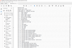
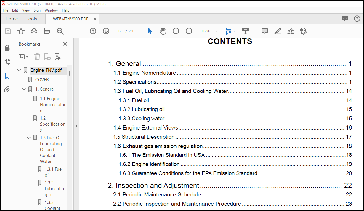
TABLE OF CONTENTS:
Komatsu 3D82AE 3D84E 3D88E 4D88E 4D98E 4D106 S4D84E S4D98E S4D106 Series Diesel Engine Shop Manual WEBMTNV000 – PDF DOWNLOAD
Engine_TNV.pdf…………………………………………………. 0
COVER……………………………………………………… 0
1. General…………………………………………………. 17
1.1 Engine Nomenclature………………………………….. 17
1.2 Specifications………………………………………. 17
1.3 Fuel Oil, Lubricating Oil and Coolant Water…………….. 30
1.3.1 Fuel oil………………………………………. 30
1.3.2 Lubricating oil………………………………… 31
1.3.3 Coolant water………………………………….. 31
1.4 Engine External Views………………………………… 32
1.5 Structural Description……………………………….. 33
1.6 Exhaust gas emission regulation……………………….. 34
1.6.1 The Emission Standard in USA…………………….. 34
1.6.2 Engine identification…………………………… 35
1.6.3 Guarantee Conditions for the EPA Emission Standard…. 36
2. Inspection and Adjustment…………………………………. 38
2.1 Periodic Maintenance Schedule…………………………. 38
2.2 Periodic Inspection and Maintenance Procedure…………… 39
2.2.1 Check before Daily Operation…………………….. 39
2.2.2 inspection after initial 50 hours operation……….. 41
2.2.3 Inspection every 50 hours……………………….. 44
2.2.4 Inspection every 250 hours or 3 months……………. 48
2.2.5 Inspection every 500 hours or 6 months……………. 51
2.2.6 Inspection every 1,000 hours or one year………….. 53
2.2.7 Inspection every 2000 hours or 2 years……………. 62
2.3 Adjusting the no-load maximum or minimum speed………….. 65
2.4 Sensor Inspection……………………………………. 66
2.4.1 Oil pressure switch…………………………….. 66
2.4.2 Thermo switch………………………………….. 66
2.5 Water leak check in cooling water system……………….. 66
2.6 Radiator cap inspection………………………………. 67
2.7 Thermostat Inspection………………………………… 67
2.8 Adjusting Operation………………………………….. 68
2.9 Long storage………………………………………… 68
3. TROUBLESHOOTING………………………………………….. 69
3.1 Preparation before troubleshooting…………………….. 69
3.2 Quick Reference Table for Troubleshooting………………. 70
3.3 Troubleshooting by measuring Compression Pressure……….. 73
4. Disassembly, Inspection and Reassembly of Engines……………. 75
4.1 Complete disassembly and reassembly……………………. 75
4.1.1 Introduction…………………………………… 75
4.1.2 Special service tools…………………………… 76
4.1.3 Complete disassembly……………………………. 81
4.1.4 Precautions before and during reassembly………….. 85
4.1.5 Adjusting operation…………………………….. 85
4.2 Cylinder Head: Disassembly, Inspection and Reassembly……. 86
4.2.1 Components (2-valve cylinder head)……………….. 86
4.2.2 Disassebly procedure:…………………………… 86
4.2.3 Reassembly procedure:…………………………… 87
4.2.4 Servicing points……………………………….. 88
4.2.5 Parts Inspection and measurement…………………. 92
4.2.6 Valve seat correction…………………………… 96
4.2.7 Valve guide replacement…………………………. 97
4.2.8 Valve stem seal replacement……………………… 98
4.3 Gear Train and Camshaft………………………………. 99
4.3.1 Components…………………………………….. 99
4.3.2 Disassembly procedure:………………………….. 99
4.3.3 Reassembly procedure:…………………………… 99
4.3.4 Servicing points………………………………..100
4.3.5 Parts inspection and measurement………………….103
4.3.6 Oil seal replacement (Gear case side)……………..105
4.3.7 Camshaft bushing replacement……………………..105
4.4 Cylinder Block……………………………………….106
4.4.1 Components……………………………………..106
4.4.2 Disassembly procedure:…………………………..106
4.4.3 Reassembly procedure:……………………………106
4.4.4 Servicing points………………………………..107
4.4.5 Parts inspection and measurement………………….111
4.4.6 Cylinder bore correction…………………………122
4.4.7 Piston pin bushing replacement……………………123
4.4.8 Oil seal replacement (Flywheel housing side)……….123
5. LUBRICATION SYSTEM………………………………………..124
5.1 Lubrication System Diagram…………………………….124
5.2 Trochoid Pump Components………………………………125
5.3 Disassembly(Reverse the procedure below for assembly)…….125
5.4 Servicing Points……………………………………..125
5.5 Parts Inspection and Measurement……………………….126
5.5.1 Trochoid pump inspection and measurement…………..126
6. COOLING SYSTEM……………………………………………128
6.1 Cooling Water System………………………………….128
6.2 Cooling Water Pump Components………………………….128
6.3 Disassembly (Reverse the procedure below for assembly)……129
6.4 Servicing Points……………………………………..129
7. FUEL INJECTION PUMP/GOVERNOR……………………………….130
7.1 Introduction…………………………………………130
7.2 Fuel Injection Pump…………………………………..130
7.2.1 Fuel system diagram……………………………..130
7.2.2 External view and components……………………..131
7.2.3 Disassembly procedure:…………………………..131
7.2.4 Assembly procedure………………………………132
7.2.5 Servicing points………………………………..132
8. TURBOCHAGER: Disassembly, inspection and reassembly…………..134
8.1 Structure and Functions……………………………….134
8.1.1 Main specifications……………………………..134
8.1.2 Construction……………………………………134
8.1.3 Structural and functional outline…………………135
8.1.4 Components……………………………………..136
8.2 Service Standards and Tightening Torque…………………137
8.2.1 Service standards……………………………….137
8.2.2 Tightening torque……………………………….138
8.3 Periodic Inspection Procedure………………………….139
8.3.1 Periodic inspection intervals…………………….139
8.3.2 Inspection procedure…………………………….140
8.3.3 Waste gate valve adjustment procedure……………..141
8.4 Disassembly Procedure…………………………………143
8.4.1 Preparation for disassembly………………………143
8.4.2 Inspection before disassembly…………………….144
8.4.3 Disassembly…………………………………….144
8.5 Washing and Inspection procedure……………………….146
8.5.1 Washing………………………………………..146
8.5.2 Inspection procedure…………………………….147
8.6 Reassembly Procedure………………………………….150
8.6.1 Preparation for reassembly……………………….150
8.6.2 Reassembly……………………………………..150
8.7 Handling after Disassembly and Reassembly……………….153
8.7.1 Instructions for turbocharger installation…………153
8.8 Troubleshooting………………………………………154
8.8.1 Excessively exhaust smoke………………………..154
8.8.2 White smoke generation…………………………..154
8.8.3 Sudden oil decrease……………………………..155
8.8.4 Decrease in output………………………………155
8.8.5 Poor (slow) response (starting) of turbocharger…….155
8.8.6 Abnormal sound or vibration………………………155
9. STARTING MOTOR……………………………………………156
9.1 For 4TNV94L/ 98………………………………………156
9.1.1 Specifications………………………………….156
9.1.2 Components……………………………………..157
9.1.3 Troubleshooting…………………………………158
9.1.4 Names of parts and disassembly procedure…………..159
9.1.5 Inspection and Maintenance……………………….163
9.1.6 Service standards……………………………….168
9.1.7 Assembly……………………………………….169
9.1.8 Characteristic test……………………………..171
9.2 For 4TNV106(T)……………………………………….172
9.2.1 Specifications………………………………….172
9.2.2 Congiguration drawing……………………………172
9.2.3 Troubleshooting…………………………………173
9.2.4 Component names and disassembly procedure………….174
9.2.5 Disassembly procedure……………………………175
9.2.6 Inspection and maintenance……………………….183
9.2.7 Assembly……………………………………….189
9.2.8 Adjustment……………………………………..190
9.2.9 Service standards……………………………….191
10. ALTERNATOR………………………………………………192
10.1 The 40A Alternator for 3TNV84 and other models………….192
10.1.1 Components…………………………………….192
10.1.2 Specifications…………………………………193
10.1.3 Wiring diagram…………………………………193
10.1.4 Standard output characteristics………………….194
10.1.5 Inspection…………………………………….194
10.1.6 Troubleshooting………………………………..195
11. ELECTRIC WIRING………………………………………….196
11.1 Electric Wiring Diagram………………………………196
11.2 PRECAUTION ON ELECTRIC WIRING…………………………197
11.2.1 Alternator…………………………………….197
11.2.2 Starter……………………………………….198
11.2.3 Current limiter………………………………..199
11.2.4 Section area and resistance of electric wire………200
12. SERVICE STANDARDS………………………………………..201
12.1 Engine Tuning……………………………………….201
12.2 Engine Body…………………………………………202
12.2.1 Cylinder head………………………………….202
12.2.2 Gear train and camshaft…………………………205
12.2.3 Cylinder block…………………………………206
12.3 Lubricating Oil System (Trochoid Pump)…………………211
13. TIGHTENING TORQUE for BOLTS and NUTS……………………….212
13.1 Tightening Torques for Main Bolts and Nuts……………..212
13.2 Tightening Torques for Standard Bolts and Nuts………….213
BACK-ADDRESS……………………………………………….. 0
More products