$33
Komatsu 4D130-1 Series Diesel Engine Shop Manual SEBE6114Z00 – PDF DOWNLOAD
Komatsu 4D130-1 Series Diesel Engine Shop Manual SEBE6114Z00 – PDF DOWNLOAD
FILE DETAILS:
Komatsu 4D130-1 Series Diesel Engine Shop Manual SEBE6114Z00 – PDF DOWNLOAD
Language : English
Pages : 220
Downloadable : Yes
File Type : PDF
Size: 17.3 MB
IMAGES PREVIEW OF THE MANUAL:

DESCRIPTION:
Komatsu 4D130-1 Series Diesel Engine Shop Manual SEBE6114Z00 – PDF DOWNLOAD
The Komatsu 4D130-1 Series Diesel Engine Shop Manual SEBE6114Z00 is a comprehensive guidebook that provides detailed technical information and instructions on how to operate, maintain, and repair the Komatsu 4D130-1 series diesel engines. These engines are commonly used in a variety of heavy equipment, such as excavators, bulldozers, and other construction machinery.
- The manual is organized into several sections, each providing detailed information on specific topics. These sections include specifications, structure and function, testing and adjusting, disassembly and assembly, maintenance, and troubleshooting.
- The specifications section of the manual provides detailed information on the engine’s physical and operational characteristics, including its dimensions, weight, performance, and power output. It also provides information on the engine’s cooling system, fuel system, and lubrication system.
- The structure and function section of the manual provides an overview of the engine’s internal components and their functions. This section includes detailed diagrams and descriptions of the engine’s various components, such as the cylinder block, cylinder head, crankshaft, pistons, and valves.
- The testing and adjusting section of the manual provides instructions on how to test and adjust the engine’s various components to ensure they are functioning correctly. This section includes detailed procedures for testing and adjusting the engine’s fuel injection system, valve clearances, and oil pressure.
- The disassembly and assembly section of the manual provides step-by-step instructions on how to disassemble and reassemble the engine’s various components. This section includes detailed diagrams and photographs to guide the user through the process.
- The maintenance section of the manual provides information on routine maintenance tasks that should be performed to keep the engine in good working condition. This section includes instructions on how to perform tasks such as changing the engine oil and replacing the air filter.
- The troubleshooting section of the manual provides guidance on how to diagnose and resolve common issues that may arise with the engine. This section includes a list of common symptoms and their likely causes, as well as step-by-step instructions for troubleshooting and resolving each issue.
TABLE OF CONTENTS:
Komatsu 4D130-1 Series Diesel Engine Shop Manual SEBE6114Z00 – PDF DOWNLOAD
COVER………………………………………… 1
CONTENTS……………………………………… 2
01 GENERAL……………………………………. 32
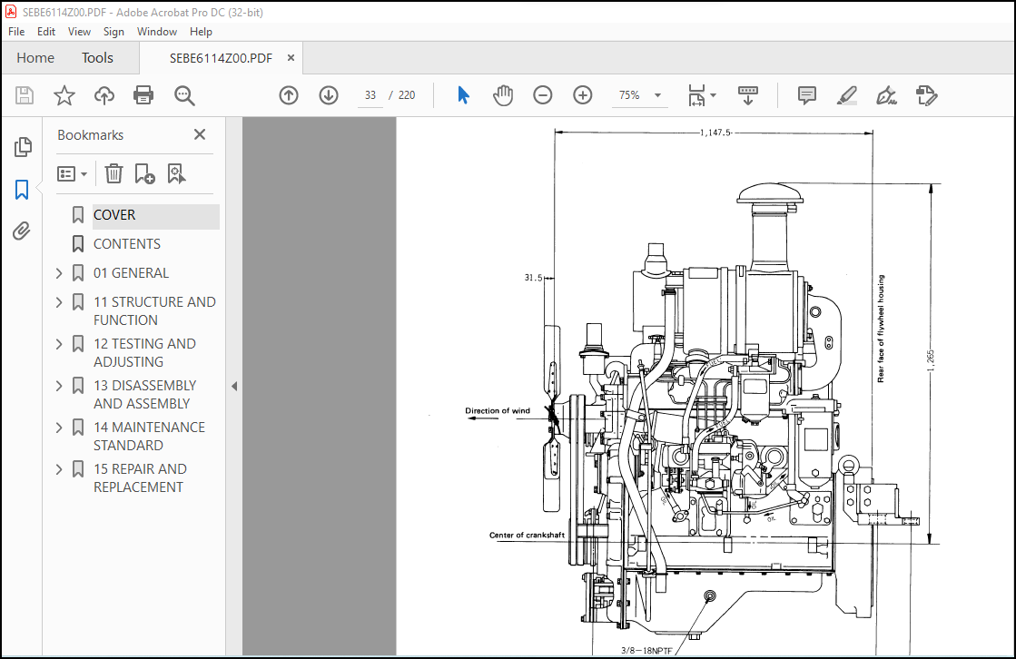
GENERAL ASSEMBLY DRAWING……………………. 33
SPECIFICATIONS…………………………….. 37
ENGINE PERFORMANCE CURVE……………………. 38
WEIGHT TABLE………………………………. 39
11 STRUCTURE AND FUNCTION………………………. 40
GENERAL STRUCTURE………………………….. 41
INTAKE AND EXHAUST UNIT…………………….. 43
CYLINDER HEAD……………………………… 44
CYLINDER BLOCK…………………………….. 47
TIMING GEAR……………………………….. 49
PISTON AND CONNECTING ROD…………………… 51
FLYWHEEL………………………………….. 52
BALANCER SHAFT…………………………….. 53
OIL PUMP………………………………….. 54
REGULATOR VALVE……………………………. 55
OIL FITER(CARTRIDGE TYPE)…………………… 56
OIL COOLER………………………………… 57
FUEL SYSTEM……………………………….. 58
FUEL INJECTION PUMP………………………… 59
GOVERNOR………………………………….. 63
FEED PUMP…………………………………. 67
INJECTION PUMP DRIVE CASE…………………… 69
FUEL INJECTION NOZZLE………………………. 70
FUEL FILTER(CARTRIDGE TYPE)…………………. 71
COOLING SYSTEM…………………………….. 72
WATER PUMP………………………………… 73
THERMOSTAT………………………………… 74
RADIATOR………………………………….. 75
CORROSION RESISTOR…………………………. 76
ELECTRICAL SYSTEM………………………….. 77
ALTERNATOR………………………………… 78
STARTING MOTOR…………………………….. 79
12 TESTING AND ADJUSTING……………………….. 80
GENERAL INSTRUCTION FOR TESTING AND ADJUSTING…. 81
INTAKE AND EXHAUST SYSTEM…………………… 82
ENGINE BODY……………………………….. 86
LUBRICATION SYSTEM…………………………. 88
FUEL SYSTEM……………………………….. 91
COOLING SYSTEM……………………………..108
PERFORMANCE TEST……………………………111
RUN-IN STANDARD…………………………….114
PERFORMANCE TEST STANDARD TABLE………………114
STANDARD FOR TESTING AND ADJUSTING……………115
TOOLS FOR TESTING AND ADJUSTING ……………..116
13 DISASSEMBLY AND ASSEMBLY……………………..117
DISASSEMBLY………………………………..118
ASSEMBLY…………………………………..142
14 MAINTENANCE STANDARD…………………………180
CYLINDER HEAD,PRECOMBUSTION CHAMBER…………..181
VALVE,VALVE GUIDE…………………………..182
ROCKER ARM,TAPPET…………………………..183
CYLINDER BLOCK……………………………..184
CYLINDER LINER……………………………..185
CRANKSHAFT…………………………………186
CAMSHAFT…………………………………..187
TIMING GEAR………………………………..188
PISTON,PISTON RING,PISTON PIN………………..189
CONNECTING ROD……………………………..190
FLYWHEEL,FLYWHEEL HOUSING……………………191
OIL PUMP…………………………………..192
REGULATOR VALVE,SAFETY VALVE…………………193
FUEL INJECTION PUMP…………………………194
GOVERNOR…………………………………..196
FEED PUMP………………………………….197
WATER PUMP,THERMOSTAT……………………….198
15 REPAIR AND REPLACEMENT……………………….199
CYLINDER HEAD SECTION……………………….200
CYLINDER BLOCK SECTION………………………205
More products