$31
Komatsu 4D92E, 4D94LE & 4D98E Diesel Engine Shop Manual 4D94E-BE4 – PDF DOWNLOAD
Komatsu 4D92E, 4D94LE & 4D98E Diesel Engine Shop Manual 4D94E-BE4 – PDF DOWNLOAD
FILE DETAILS:
Komatsu 4D92E, 4D94LE & 4D98E Diesel Engine Shop Manual 4D94E-BE4 – PDF DOWNLOAD
Language : English
Pages : 160
Downloadable : Yes
File Type : PDF
Size: 4.27 MB
IMAGES PREVIEW OF THE MANUAL:
DESCRIPTION:
Komatsu 4D92E, 4D94LE & 4D98E Diesel Engine Shop Manual 4D94E-BE4 – PDF DOWNLOAD
APPLICABLE MACHINE SERIAL NO. APPLICABLE ENGINE
FD10/15/18-20 650001 and up 4D92E
FD20/25/30-16 700001 and up 4D94LE
FD20N/25N/30N-16 700001 and up 4D94LE
FD20H/25H/30H/35A-16 700001 and up 4D98E
The Komatsu 4D92E, 4D94LE, and 4D98E Diesel Engine Shop Manual, also known as the 4D94E-BE4 manual, is a comprehensive guide to servicing, maintaining, and repairing these diesel engines. The manual is published by Komatsu, a leading manufacturer of heavy equipment and construction machinery, and is designed for use by qualified mechanics and technicians.
These engines are commonly used in a wide range of heavy equipment, such as excavators, bulldozers, and loaders. The manual covers all aspects of these engines, including their specifications, features, and operating principles. It is an essential tool for anyone who works with Komatsu equipment that is powered by these engines.
The manual is divided into several sections, each of which provides specific information on different aspects of the engine. The sections include:
- General information: This section provides an overview of the engine, including its specifications, features, and operating principles. It also includes information on safety precautions, tools, and equipment needed for maintenance and repair.
- Inspection and adjustment: This section provides detailed instructions on how to inspect and adjust various components of the engine, including the cylinder head, valves, fuel system, and cooling system.
- Engine disassembly and assembly: This section provides step-by-step instructions on how to disassemble and assemble the engine. It includes detailed diagrams and illustrations to help users understand each step of the process.
- Troubleshooting: This section provides a comprehensive list of potential problems that may arise with the engine, along with diagnostic procedures to help identify and fix these issues.
- Maintenance: This section provides information on the regular maintenance tasks that should be performed on the engine, including oil changes, filter replacements, and other routine tasks.
- Reassembly and testing: This section provides detailed instructions on how to reassemble the engine after repairs have been made. It also includes information on how to test the engine to ensure that it is functioning properly.
- Service data: This section provides detailed technical data on the engine, including torque specifications, compression pressures, and other important information.
The manual is written in clear, concise language and is filled with detailed diagrams and illustrations to help users understand each step of the process. It is an essential tool for anyone who works with Komatsu engines and can help to ensure that the engine is maintained and repaired to the highest standards. However, it should be noted that the manual is designed for use by qualified mechanics and technicians and should not be used by individuals without the appropriate training and experience.
TABLE OF CONTENTS:
Komatsu 4D92E, 4D94LE & 4D98E Diesel Engine Shop Manual 4D94E-BE4 – PDF DOWNLOAD
4D94E-BE4…………………………………………………………………….. 1
CONTENTS………………………………………………………………….. 2
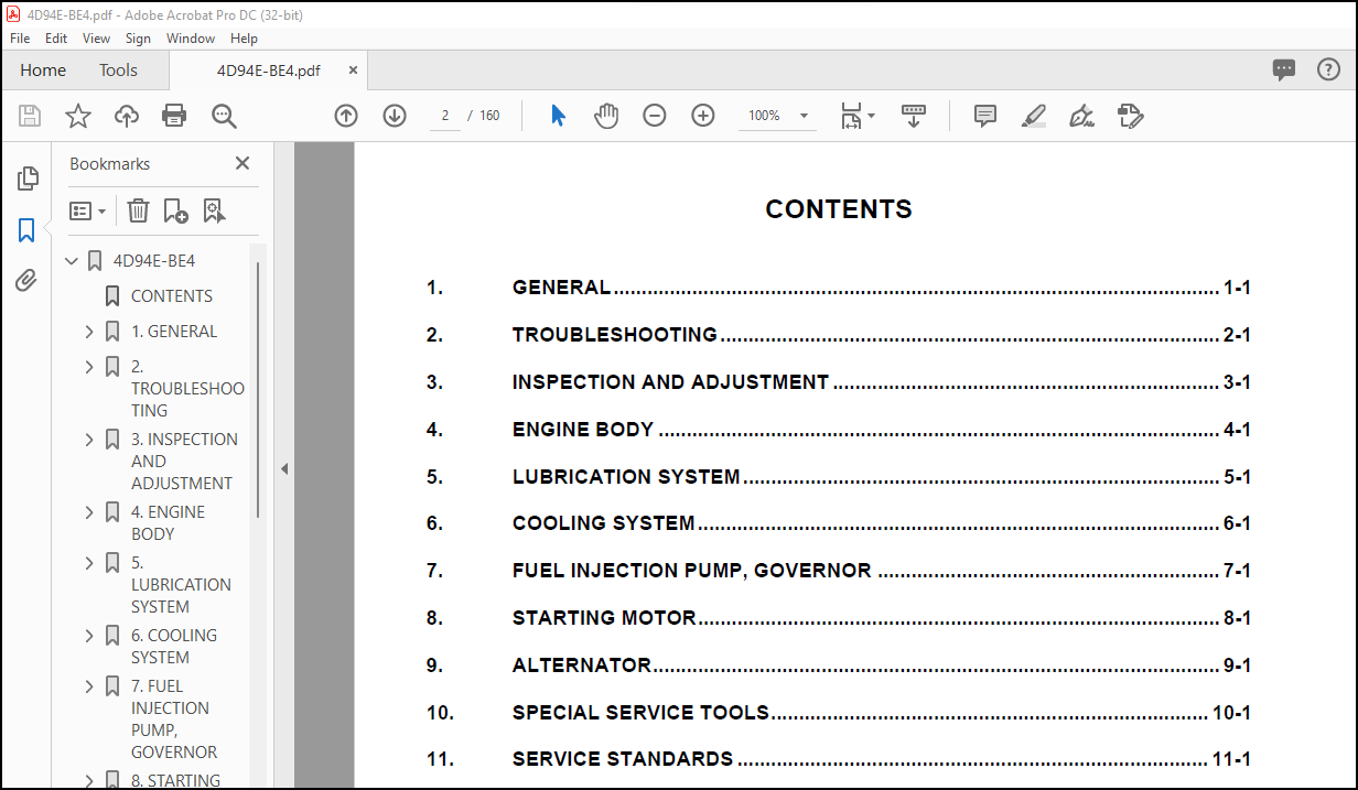
1. GENERAL………………………………………………………………… 3
1-1 Specifications……………………………………………………… 4
1-2 Fuel oil, lubricating oil and cooling water……………………………. 5
1-3 Engine performance curve…………………………………………….. 6
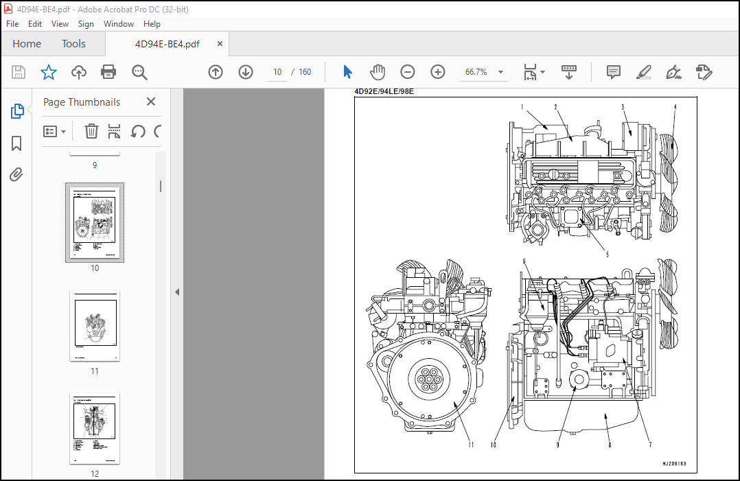
1-4 Engine external views……………………………………………….. 10
1-5 Structural description………………………………………………. 12
1-6 How to read this manual……………………………………………… 14
1-7 Precautions for service work…………………………………………. 16
1-8 Tightening torques for standard bolts and nuts…………………………. 17
2. TROUBLESHOOTING…………………………………………………………. 19
2.1 Quick reference table for troubleshooting……………………………… 20
2.2 Troubleshooting by measuring compression pressure………………………. 24
3. INSPECTION AND ADJUSTMENT………………………………………………… 27
3-1 Inspecting water leak from cooling water system and radiator…………….. 28
3-2 Fan belt tension inspection and adjustment…………………………….. 29
3-3 Adjusting the valve clearance………………………………………… 30
3-4 Testing injection pressure and spraying condition of fuelinjection nozzle…. 31
3-5 Testing and adjusting fuel injection timing mark……………………….. 35
3-6 Adjusting no-load engine speed……………………………………….. 36
3-7 Sensor inspection…………………………………………………… 37
3-8 Battery inspection………………………………………………….. 38
3-9 Adjusting operation…………………………………………………. 40
3-10 Long storage………………………………………………………. 40
3-11 Periodic maintenance schedule……………………………………….. 41
4. ENGINE BODY…………………………………………………………….. 43
4-1 Introduction……………………………………………………….. 44
4-2 Cylinder head………………………………………………………. 45
4-3 Gear train and camshaft……………………………………………… 54
4-4 Cylinder block……………………………………………………… 59
5. LUBRICATION SYSTEM………………………………………………………. 73
5-1 Lubrication system diagram…………………………………………… 74
5-2 Trochoid pump components…………………………………………….. 74
5-3 Disassembly (reverse the procedure below for assembly)………………….. 75
5-4 Servicing points……………………………………………………. 75
5-5 Parts inspection and measurement……………………………………… 76
6. COOLING SYSTEM………………………………………………………….. 77
6-1 Cooling water system………………………………………………… 78
6-2 Cooling water pump components………………………………………… 79
6-3 Disassembly (reverse the procedure below for assembly)………………….. 79
6-4 Servicing points……………………………………………………. 79
7. FUEL INJECTION PUMP, GOVERNOR…………………………………………….. 81
7-1 Specifications……………………………………………………… 82
7-2 Component parts…………………………………………………….. 83
7-3 Fuel injection pump system diagram……………………………………. 84
7-4 Removal and installation of fuel injection pump………………………… 85
7-5 Fuel system………………………………………………………… 86
7-6 Structure and operation of pump………………………………………. 88
7-7 Operation of plunger………………………………………………… 92
7-8 All speed governor………………………………………………….. 98
7-9 Structure and operation of timer………………………………………106
7-10 Magnet valve……………………………………………………….108
7-11 Improvement of startability at very low temperature…………………….109
8. STARTING MOTOR…………………………………………………………..111
8-1 Specifications………………………………………………………112
8-2 Components………………………………………………………….113
8-3 Troubleshooting……………………………………………………..114
8-4 Names of parts and disassembly procedure……………………………….115
8-5 Inspection and maintenance……………………………………………119
8-6 Service standards……………………………………………………125
8-7 Assembly……………………………………………………………126
8-8 Characteristic test………………………………………………….128
9. ALTERNATOR………………………………………………………………129
9-1 Specifications………………………………………………………130
9-2 Sectional view………………………………………………………131
9-3 Troubleshooting……………………………………………………..132
9-4 Parts names and disassembly procedure………………………………….133
9-5 Inspection and overhaul………………………………………………136
9-6 Assembly……………………………………………………………140
9-7 Service standards……………………………………………………141
9-8 Performance test…………………………………………………….142
10. SPECIAL SERVICE TOOLS……………………………………………………143
10.1 Special tools………………………………………………………144
10.2 Measuring instruments……………………………………………….146
11. SERVICE STANDARDS……………………………………………………….149
11-1 Engine tuning………………………………………………………150
11-2 Engine body………………………………………………………..151
11-3 Lubricating oil system (trochoid pump)………………………………..155
11-4 Tightening torques for main parts…………………………………….156
BACK COVER…………………………………………………………………160
More products