$33
Komatsu 4D98 Series 4D106 Series S4D10S6 Series Diesel Engine Shop Manual WEBM4D9801 – PDF DOWNLOAD
Komatsu 4D98 Series 4D106 Series S4D10S6 Series Diesel Engine Shop Manual WEBM4D9801 – PDF DOWNLOAD
FILE DETAILS:
Komatsu 4D98 Series 4D106 Series S4D10S6 Series Diesel Engine Shop Manual WEBM4D9801 – PDF DOWNLOAD
Language : English
Pages : 182
Downloadable : Yes
File Type : PDF
Size: 9.04 MB
IMAGES PREVIEW OF THE MANUAL:
DESCRIPTION:
Komatsu 4D98 Series 4D106 Series S4D10S6 Series Diesel Engine Shop Manual WEBM4D9801 – PDF DOWNLOAD
The Komatsu 4D98 Series, 4D106 Series, S4D106 Series Diesel Engine Shop Manual WEBM4D9801 is a technical manual that provides comprehensive information and instructions for the maintenance, repair, and overhaul of several Komatsu diesel engines. These engines are commonly used in Komatsu construction equipment, including excavators, bulldozers, and wheel loaders.
- The manual is organized into several sections, each of which covers different aspects of engine maintenance and repair. The sections include general specifications, testing and adjusting procedures, disassembly and assembly instructions, and troubleshooting guidelines.
- The general specifications section provides an overview of the engine’s technical specifications, including its dimensions, weight, power output, and torque ratings. It also includes information on the engine’s various components, such as the cylinder block, cylinder head, crankshaft, and pistons.
- The testing and adjusting procedures section of the manual provides step-by-step instructions for performing various tests and adjustments on the engine. These procedures include compression tests, fuel injection timing adjustment, and valve clearance adjustment. The manual also provides information on the tools and equipment required for performing these procedures.
- The disassembly and assembly instructions section of the manual provides detailed guidance on how to disassemble and reassemble the engine, including the removal and installation of various components such as the cylinder head, pistons, and crankshaft. This section also includes detailed diagrams and illustrations that provide a clear understanding of the engine’s internal components and how they fit together.
- The troubleshooting guidelines section of the manual provides information on how to diagnose and repair common problems that may occur with the engine. This section provides a list of potential symptoms and causes, along with step-by-step instructions for identifying and fixing the problem.
- Overall, the Komatsu 4D98 Series, 4D106 Series, S4D106 Series Diesel Engine Shop Manual WEBM4D9801 is an essential resource for technicians and mechanics working with the Komatsu 4D98, 4D106, and S4D106 engines. Its comprehensive coverage of maintenance, repair, and troubleshooting procedures make it an indispensable tool for ensuring the reliable and efficient operation of Komatsu construction equipment.
TABLE OF CONTENTS:
Komatsu 4D98 Series 4D106 Series S4D10S6 Series Diesel Engine Shop Manual WEBM4D9801 – PDF DOWNLOAD
MAIN MENU………………………………………………………………….. 0
FOREWORD ………………………………………………………………….. 4
FOR SAFE SERVICING………………………………………………………….. 5
PRECAUTIONS FOR SAFE SERVICING……………………………………………….. 6
(A) Service Shop (Place) ………………………………………………… 6
(B) Working Wear ……………………………………………………….. 7
(C) Tools to Be Used ……………………………………………………. 7
(D) Use of Genuine Parts, Oil and Grease ………………………………….. 7
(E) Bolt and Nut Tightening Torques ………………………………………. 7
(F) Electrical Parts ……………………………………………………. 8
(G) Waste Treatment …………………………………………………….. 8
(H) Handling the Product ………………………………………………… 9
CONTENTS ………………………………………………………………….. 10
1. GENERAL ……………………………………………………………….. 11
1.1 Engine Nomenclature …………………………………………………. 12
1.2 Specifications …………………………………………………….. 13
1.3 Fuel Oil, Lubricating Oil and Cooling Water …………………………. 17
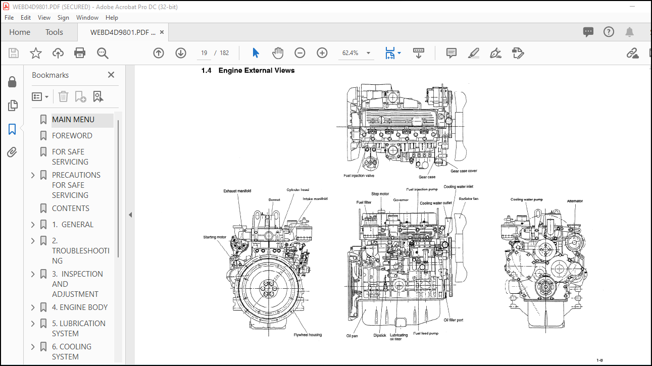
1.4 Engine External Views………………………………………………… 19
1.5 Structural Description……………………………………………….. 20
1.6 How to Read This Manual………………………………………………. 21
(1) Range of Operation Explanation…………………………………….. 21
(2) How to Read The Explanations………………………………………. 21
(3) Definition of Terms………………………………………………. 22
(4) Abbreviations……………………………………………………. 22
1.7 Precautions for Service Work………………………………………….. 23
1.8 Tightening Torques for Standard Bolts and Nuts………………………….. 24
2. TROUBLESHOOTING ………………………………………………………… 25
2.1 Quick Reference Table for Troubleshooting………………………………. 26
2.2 Troubleshooting by Measuring Compression Pressure ………………………. 29
(1) Compression pressure measurement method…………………………….. 29
(2) Standard compression pressure……………………………………… 29
(3) Engine speed and compression pressure (reference)……………………. 30
(4) Measured value and troubleshooting…………………………………. 30
3. INSPECTION AND ADJUSTMENT……………………………………………….. 31
3.1 Oil Inspection ……………………………………………………… 32
3.2 Cooling Water Inspection …………………………………………….. 32
3.3 Inspecting Water Leak from Cooling Water System and Radiator …………….. 32
3.4 Fan Belt Tension Inspection and Adjustment …………………………….. 33
3.5 Adjusting the Valve Clearance ………………………………………… 34
3.6 Inspecting the Fuel Injection Valve Injection Pressure and Spray Pattern …. 35
3.7 Fuel Injection Timing Inspection and Adjustment…………………………. 39
3.8 Adjusting the No-load Maximum (or Minimum) Revolutions ………………….. 40
3.9 Sensor Inspection …………………………………………………… 41
3.10 Battery Inspection …………………………………………………. 42
3.11 Adjusting Operation ………………………………………………… 44
3.12 Long Storage ………………………………………………………. 45
3.13 Periodic Maintenance Schedule ……………………………………….. 46
4. ENGINE BODY …………………………………………………………….. 47
4.1 Introduction ……………………………………………………….. 49
4.2 Cylinder Head ………………………………………………………. 50
(1) Components………………………………………………………. 50
(2) Disassembly procedure:……………………………………………. 50
(3) Reassembly procedure:…………………………………………….. 51
(4) Servicing points…………………………………………………. 51
(5) Parts Inspection and measurement…………………………………… 53
(6) Valve seat correction…………………………………………….. 56
(7) Valve guide replacement…………………………………………… 58
(8) Valve stem seal replacement……………………………………….. 58
4.3 Gear Train and Camshaft ……………………………………………… 59
(1) Components………………………………………………………. 59
(2) Disassembly procedure:……………………………………………. 59
(3) Reassembly procedure:…………………………………………….. 59
(4) Servicing points…………………………………………………. 60
(5) Parts inspection and measurement…………………………………… 62
(6) Oil seal replacement……………………………………………… 64
(7) Camshaft bushing replacement………………………………………. 64
4.4 Cylinder block………………………………………………………. 65
(1) Components……………………………………………………… 65
(2) Disassembly procedure……………………………………………. 65
(3) Reassembly procedure…………………………………………….. 65
(4) Servicing points………………………………………………… 66
(5) Parts inspection and measurement………………………………….. 69
(6) Cylinder bore correction…………………………………………. 77
(7) Piston pin bushing replacement……………………………………. 78
(8) Oil seal replacement…………………………………………….. 78
5. LUBRICATION SYSTEM……………………………………………………….. 79
5.1 Lubrication System Diagram …………………………………………… 80
5.2 Trochoid Pump Components …………………………………………….. 80
5.3 Disassembly (Reverse the procedure below for assembly) ………………….. 81
5.4 Servicing Points ……………………………………………………. 81
5.5 Parts Inspection and Measurement ……………………………………… 81
6. COOLING SYSTEM…………………………………………………………… 82
6.1 Cooling Water System ………………………………………………… 83
6.2 Cooling Water Pump Components ………………………………………… 83
6.3 Disassembly (Reverse the procedure below for assembly)…………………… 84
6.4 Servicing Points ……………………………………………………. 84
7. FUEL INJECTION PUMP/GOVERNOR……………………………………………… 85
7.1 Introduction ……………………………………………………….. 86
7.2 Fuel Injection Pump …………………………………………………. 86
(1) Fuel system diagram………………………………………………. 86
(2) Components………………………………………………………. 87
(3) Disassembly procedure:……………………………………………. 87
(4) Assembly procedure……………………………………………….. 88
(5) Servicing points…………………………………………………. 88
(6) Parts inspection and measurement…………………………………… 90
7.3 Fuel Injection Valve ………………………………………………… 92
7.4 Fuel Feed Pump………………………………………………………. 92
(1) Components………………………………………………………. 92
(2) Disassembly procedure (Reverse the procedure below for assembly.)……… 92
(3) Parts inspection and measurement…………………………………… 92
7.5 Governor……………………………………………………………. 93
(1) Components………………………………………………………. 93
(2) Disassembly procedure (Reverse the procedure for assembly.)…………… 93
(3) Parts inspection and measurement…………………………………… 94
7.6 Special Service Tools for Disassembly/Assembly …………………………. 94
8. TURBOCHARGER (FOR 4TNE106T) …………………………………………….. 95
8.1 Structure and Functions ……………………………………………… 97
(1) Structural and functional outline………………………………….. 97
(2) Structure……………………………………………………….. 98
(3) Components………………………………………………………. 99
8.2 Service Standards ……………………………………………………100
(1) Service standards…………………………………………………100
(2) Tightening torque…………………………………………………100
8.3 Periodic Inspection Procedure …………………………………………101
(1) Periodic inspection intervals………………………………………101
(2) Inspection procedure………………………………………………101
(3) Waste gate valve adjustment procedure……………………………….102
8.4 Disassembly Procedure ………………………………………………..104
(1) Preparation for disassembly………………………………………..104
(2) Inspection before disassembly………………………………………105
(3) Disassembly………………………………………………………105
8.5 Washing and Inspection procedure……………………………………….106
(1) Washing………………………………………………………….106
(2) inspection procedure………………………………………………107
8.6 Reassembly Procedure …………………………………………………110
(1) Preparation for reassembly…………………………………………110
(2) Reassembly……………………………………………………….110
8.7 Handling after Disassembly and Reassembly ………………………………112
8.8 Troubleshooting ……………………………………………………..113
9. STARTING MOTOR ………………………………………………………….115
9.1 FOR 4TNE94/98………………………………………………………..117
9.1.1 Specifications………………………………………………….117
9.1.2 Components……………………………………………………..118
9.1.3 Troubleshooting…………………………………………………119
9.1.4 Names of parts and disassembly procedure…………………………..120
9.1.5 Inspection and Maintenance……………………………………….124
(1) Armature……………………………………………………..124
(2) Field coil……………………………………………………126
(3) Brush………………………………………………………..126
(4) Brush holder………………………………………………….127
(5) Magnetic switch……………………………………………….127
(6) Pinion clutch…………………………………………………128
9.1.6 Service standards……………………………………………….130
9.1.7 Assembly……………………………………………………….131
9.1.8 Characteristic test……………………………………………..133
9.2 FOR 4TNEl06(T) ………………………………………………………134
9.2.1 Specifications………………………………………………….134
9.2.2 Configuration drawing……………………………………………134
9.2.3 Troubleshooting…………………………………………………135
9.2.4 Component names and disassembly procedure………………………….136
9.2.5 Disassembly procedure……………………………………………137
9.2.6 Inspection and maintenance……………………………………….139
(1) Armature……………………………………………………..139
(2) Field coil……………………………………………………141
(3) Brush………………………………………………………..141
(4) Magnetic switch continuity test…………………………………142
(5) Pinion……………………………………………………….143
(6) Ball bearing………………………………………………….143
9.2.7 Assembly……………………………………………………….143
9.2.8 Adjustment……………………………………………………..144
9.2.9 Service standards……………………………………………….145
10. ALTERNATOR …………………………………………………………….146
10.1 For 4TNE94/98 ………………………………………………………147
10.1.1 Specifications ………………………………………………..147
10.1.2 Section view…………………………………………………..148
10.1.3 Troubleshooting………………………………………………..149
10.1.4 Parts names and disassembly procedure ……………………………150
10.1.5 Inspection and overhaul ………………………………………..153
(1) Diode………………………………………………………..153
(2) Rotor………………………………………………………..153
(3) Stator……………………………………………………….154
(4) Brush………………………………………………………..155
(5) Check of IC regulator………………………………………….155
10.1.6 Assembly ……………………………………………………..157
10.1.7 Service standards ……………………………………………..158
10.1.8 Performance test ………………………………………………159
10.2 For 4TNE106(T) ……………………………………………………..160
10.2.1 Specifications (1) ……………………………………………160
10.2.2 Exploded View …………………………………………………161
10.2.3 Troubleshooting ……………………………………………….162
10.2.4 Disassembly Procedure ………………………………………….163
10.2.5 Inspection and Maintenance ……………………………………..164
10.2.6 Reassembly Procedure …………………………………………..165
10.2.7 Performance Test ………………………………………………166
11. SPECIAL SERVICE TOOLS……………………………………………………168
11.1 Special Tools ………………………………………………………169
11.2 Measuring Instruments ……………………………………………….171
12. SERVICE STANDARDS ………………………………………………………174
12.1 Engine Tuning ………………………………………………………175
12.2 Engine Body ………………………………………………………..176
(1) Cylinder head…………………………………………………….176
(2) Gear train and camshaft……………………………………………177
(3) Cylinder block……………………………………………………178
12.3 Lubricating Oil System (Trochoid Pump) ………………………………..180
12.4 Tightening Torques for Main Bolts and Nuts …………………………….181
More products